
J. Cent. South Univ. (2017) 24: 459-466
DOI: 10.1007/s11171-017-3448-x

6-DOF motion estimation using optical flow based on dual cameras
LIU Meng-yao(������)1, WANG Yan(����)1, GUO Lei(����)1, 2
1. School of Automation Science and Electrical Engineering, Beihang University, Beijing 100191, China;
2. Science and Technology on Aircraft Control Laboratory, Beihang University, Beijing 100191, China
 Central South University Press and Springer-Verlag Berlin Heidelberg 2017
Abstract:
Because of its characteristics of simple algorithm and hardware, optical flow-based motion estimation has become a hot research field, especially in GPS-denied environment. Optical flow could be used to obtain the aircraft motion information, but the six-(degree of freedom) (6-DOF) motion still couldn��t be accurately estimated by existing methods. The purpose of this work is to provide a motion estimation method based on optical flow from forward and down looking cameras, which doesn��t rely on the assumption of level flight. First, the distribution and decoupling method of optical flow from forward camera are utilized to get attitude. Then, the resulted angular velocities are utilized to obtain the translational optical flow of the down camera, which can eliminate the influence of rotational motion on velocity estimation. Besides, the translational motion estimation equation is simplified by establishing the relation between the depths of feature points and the aircraft altitude. Finally, simulation results show that the method presented is accurate and robust.
Key words:
optical flow; motion estimation; dual cameras; six degree-of-freedom (6-DOF)��
1 Introduction
Computer vision research has made great progress in recent decades and showed great potential of application in unmanned aerial vehicle (UAV) navigation, because vision sensors can help the aircraft to sense the external environment and full information, and usually have low cost, small volume and light weight [1].
Birds and insects use optical flow to control speed, avoid obstacles, autonomous land and take off. Inspired by this navigation mechanism, researchers began to explore methods to apply optical flow in aircraft navigation [2]. Optical flow means the apparent motion of brightness patterns or feature points, observed by the eye or the camera, caused by the relative motion between the observer and surroundings. It could be calculated by image sequence obtained during flight, and used to analyze the relative motion [3].
After years of development, optical flow techniques have been successfully employed in UAV, being an important means of auxiliary or independent navigation. Obstacle avoidance strategy based on forward-looking camera has been commonly used [4], and so is down-looking camera based motion estimation and positioning [5-8]. But the latter is usually realized by down camera alone to gain 6-DOF motion information [8, 9], thus velocity estimation is of less accuracy when substantial rotational movement exists [10]. It can be avoided by assuming the aircraft is in level flight and carrying out in the 2D case, but this assumption has great limitations and cannot be well applied to the actual flight. Containing richer message than down camera, front camera can be used in not only obstacle avoidance, but also the rotational movement estimation [11]. So a better motion estimation and positioning task could be accomplished by combining these two cameras. Besides, existing optical flow motion estimation models take depth of each feature point as state variable, resulting in large amount of computation because system dimension increases when adding new feature points as measurement [12].
The distribution feature and the decoupling method of optical flow are used in this paper to calculate the angular velocities of aircraft and update the attitude angles. In order to eliminate the influence of rotational motion on speed estimation, the translational flow of down-looking camera is calculated using resulted
angular velocities, thus this method doesn��t rely on the assumption of level flight. Besides, the attitude angles can be used to establish the relation between the depth of feature point and the vertical height of aircraft from the ground. Finally, the simplified translational motion estimation equation is used as the measurement equation of the unscented Kalman filter, and translational velocities under three-dimensional motion are calculated. The system has four state variables and adding feature points only increases the amount of measurement information, instead of increasing the system dimension, which could reduce the amount of computation and improve the operation rate.
2 Feature-point-based pyramid LK optical flow algorithm
Optical flow could be obtained by some algorithms from the image sequence captured by the camera. At present, typical optical flow algorithms include differential methods, feature-based methods, image interpolation method, phase-based methods, region- based matching methods, etc. [13].
The optical flow algorithm based on SIFT feature detection provides the best performance, because the features used are invariant to image scale and rotation, and partially to affine distortion and illumination changes [14]. However, SIFT requires a large amount of calculation, not suitable for the real-time navigation. Meanwhile, Lucas-Kanade method, one of the differential methods, has simple implementation, low computational complexity, and hence more widespread use. LK method matches the corresponding regions between two images by using the gradient of grey image [15]. This method is inaccuracy when the large displacement exists, which in fact frequently occurs in aircraft motion. To solve this problem, image pyramid is used, in which the image resolution is reduced level by level. So, the optical flow caused by large movement should be first calculated by the top image and the error is calculated progressively through lower images, which in result improves the calculation accuracy of large optical flow.
In this work, the feature-point-based pyramid LK optical flow algorithm is used. Firstly, locate the corners in the image by Harris algorithm and compute their subpixel positions. Then, calculate optical flow at the positions of corners instead of all pixels. In this way, the amount of calculation is greatly reduced, the accuracy is improved and the real-time optical flow navigation will be realized. Furthermore, errors of the LK algorithm will be further decreased through image preprocessing techniques.
3 Motion estimation based on optical flow
3.1 Optical flow motion estimation model and decoupling method
To get the optical motion estimation model used in this article, we start from the case which evolved just one pinhole forward-looking camera, and then the estimation model of down-looking camera is similar deduced. The inertial coordinate system Fe, body coordinate system Fb and front camera coordinate system Fc1 are defined as shown in Fig. 1. The feature point i in 3D space is described by  in Fc1, among which
  is the depth of i, and
  in Fe. UAV is located relative to Fe by
 . During flight, there is the following geometric relationship
  . Assume that the camera is fixed at mass center of the UAV, which means
  and at the same time the feature point is stationary relative to Fe, which means
  thus the derivation of the formula in Fc1 can be obtained.
 (1)
(1)
where  and
and  in Eq. (1) represent the body-axis translational and angular velocities in Fb, respectively.

Fig. 1 Geometrical relationship schematic
Set coordinates of point i in Fc1 as  then according to the principle of a pinhole camera(Fig. 2), the image coordinate of projection of i is
  , which is determined by the following formula. In Eq.(2), f is the focus length, an intrinsic camera parameter.
 (2)
(2)
The displacement of the projection point on the image plane can be obtained through derivation calculus to above equation, which is in other words the optical flow of the point.
 (3)
(3)

Fig. 2 Imaging principle
Now, substitute the transformation matrix  between Fb and Fc1 into Eq. (1), and substitute the resulted equation into Eq. (3), then the motion estimation equation of front camera expressed by aircraft motion parameters can be obtained, as shown by Eq. (4).

 (4)
(4)
In the formula,  and
and  represent the translational and rotational optical flow of i respectively.
 and
and  are the translational and angular velocities of aircraft with respect to Fb.
  is the third coordinate of the feature point in the camera coordinate system, and means the depth of i. The same procedure may be easily adopted to obtain down-looking camera motion estimation equation, among which j is a feature point captured by the down- looking camera.

 (5)
(5)
It can be seen from above equations that, the optical flow can be decoupled into translational and rotational parts. The former is correlated with translational velocities and depths of feature points, while the latter is only correlated with rotational velocities.
3.2 Motion estimation based on forward-looking camera
Consider a simplified situation in which rotational motion doesn��t exist. Optical flow of each point is caused by translational motion of aircraft, and their extension lines intersect at a point  of Fig. 3 whose position depends on translational velocities and in consistent with the direction of aircraft��s movement [16].

Fig. 3 Focus of expansion caused by translational OF
 (6)
(6)
As mentioned above, optical flow can be decoupled into two parts, and rotational part is irrelevant to depths, which can be used to avoid using unavailable depths during the rotational velocities calculation. So, equation of rotational optical flow expressed by (ui, vi) and (px, py) can be obtained by substituting Eq. (7) into Eq. (8).
 (7)
(7)
 (8)
(8)
By substituting the rotational optical flow motion equation, which can be obtained from Eq. (4), into the equation resulted above, a nonlinear equation of ��, (ui, vi) and (px, py) can be obtained, as shown in Eq. (9).


 (9)
(9)
A system of nonlinear equations can be established by collecting M feature points and the least square solution of �� can be calculated by using the generalized inverse method. Then attitude angles, pitch ��, yaw ��, and roll �� of the UAV, can be obtained by means of numerical integral.
Increased forward-looking camera can also be used to calculate the attack and sideslip angle, fulfill other navigation tasks like obstacle avoidance, and increase system stability and reliability by fusion with data from the IMU.
3.3 Motion estimation based on down-looking camera
1) Image preprocessing
In this section, translational velocities are estimated by optical flow obtained from the down-looking camera based on following assumptions. 1) Feature points observed by the down-looking camera are on the same level. 2) The plane of feature points changes continuously in height between images.
The estimation can be affected by substantial change in height, due to the relationship between translational optical flow and the depth. Thus, the segmentation of down-looking image is necessary to extract the ground or background with large area ratio as the selected area, which is consistent in the adjacent images unless unable to extract enough feature points because of shrinkage. Then feature points are selected in the selected area and the optical flow of the points can be calculated. The extraction of optical flow computing area in advance could reduce the impact of substantial change in depth when obstacles appear on the ground, and guarantee feature points of an image captured by down-looking camera mostly on the same level.
Predicted optical flow of a feature point can be calculated using prediction data of UKF. Then, the feature point is used for velocity estimation only when difference between predicted and calculated optical flow of this point is less than a threshold. This method can reduce errors caused by pyramid LK algorithm.
2) Depths under three-dimensional motion
First, the feature point j is captured by the down- looking camera and the rotational optical flow  of j is calculated by using
  which are obtained by the front camera motion estimation. Then, the translational optical flow
  can be calculated.
As we know, translational optical flow is correlated with depths of the captured feature points, which can��t be treated as the same under three-dimensional motion of the aircraft. So, it is necessary to calculate the depth of each point respectively, through using attitude angles of aircraft, vertical height from ground and projection coordinates on image plane.
 (10)
(10)
The optical center and the feature point j form a straight line lj, which can be described as the following equation according to the pinhole camera model.
 (11)
(11)
Assume that the ground below is horizontal, and can be described by  with respect to Fe. Position of down camera with respect to Fe is
  , and the vertical height of the aircraft from ground is
 The translation matrix between Fe and Fb could be written as Eq. (12).
 (12)
(12)
Using the attitude angles  obtained by front camera motion estimation, the rotation matrix between Fe and Fb could be written as follows.
 (13)
(13)
The rotational matrix between Fe and Fc2 can be written as follows.
 (14)
(14)
The homogeneous coordinates are used here, so the dimension of rotational matrix increases and the rotational matrix can be written as following.
 (15)
(15)
Take a point on the ground, which can be written as  in the form of homogeneous coordinates with respect to Fe, which can be multiplied by a translation matrix and a rotation matrix successively to calculate coordinated in Fc2.
 (16)
(16)
The projection of the mass center of UAV on the ground is in Fe, which could be transformed to
  in Fc2. Besides, based on the assumption that the ground is level, the normal vector of the ground in Fe is
  and can be transformed to
  in Fc2. Then the ground surface in Fc2 can be expressed asR13(X+R13h)+R23(Y+R23h)+R33(Z+R33h)=0, which is R13X+R23Y+R33Z
 Solve the line and plane equations, the depth of j can be written as:
 (17)
(17)
3) Translational velocity estimation
Substitute Eq. (16) into Eq. (9) to get a new simplified translational optical flow motion estimation equation.
 (18)
(18)
In this work, speed estimation is realized by the method of UKF algorithm, which is designed as follows.
State equation:
Measurement equation:
 is the system state vector, among which
  is the aircraft translational velocity in Fb, and h is the vertical height of the aircraft from ground.
 ~
~ is the process noise.
  is the system measurement vector consisting of translational optical flow of N feature points.
  ~
~ is the measurement noise. Set Eq. (17) as g(Xk) in the system measurement equation and Eq. (18) as the system state equation.
 (19)
(19)
Using the state and measurement equation given above, the translational velocity could be obtained based on the UKF algorithm.
4 Simulation results
4.1 Rotational motion estimation in 2D environment
In this simulation, feasibility of the rotational motion estimation in two-dimensional motion was verified. A forward-looking camera was installed on the top of the car and triggered at 10 frames per second. Total distance of the movement was 123 m, and simulation time was 15 s. Image sequences were downloaded from the KITTI Vision Benchmark Suite [17].
The results (Fig. 4) show that the rotational motion estimation is still accurate and reliable when substantial rotational movement exists.
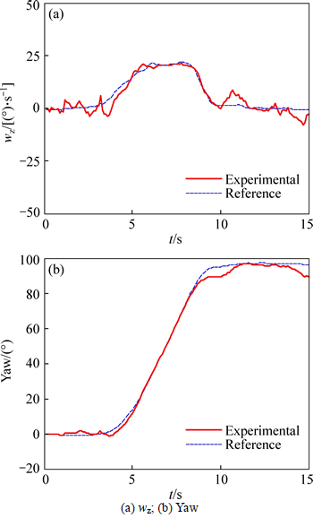
Fig. 4 Rotational motion estimation results:
4.2 Simulation in 3D environment
A virtual environment, as shown in Fig. 5, is set up using OpenGL in order to simulate the indoor navigation for aircraft.
1) Translational motion estimation
Motion estimation of down-looking camera is usually less accurate when the vertical height from ground changes. It��s necessary to verify the reliability of the new translational motion estimation equation presented in this paper. In this simulation, total distance of the movement was 40 m, and simulation time was 20 s.

Fig. 5 Simulation environment
A down-looking camera was used and triggered at 20 frames per second. There was no rotational movement in this simulation, and the translational motion path is shown in Fig. 6.
The results given in Fig. 7 show the applicability and accuracy of the translational motion estimation equation. There is no divergence or drift, even when fight attitude changes.
2) 6-DOF motion estimation
In this simulation, aircraft was moving straight, and it��s attitude angles changed in the sinusoidal form. Total distance of the movement was 5 m, and simulation time was 10 s. Cameras were triggered at the frequency of 20 Hz. The three-dimensional motion parameters were estimated by dual cameras and single down camera separately, using the same amount of feature points, to verify that motion parameters could be better estimated by dual cameras. Rotational and translational motion estimations are shown in Figs. 8 and 9.

Fig. 6 Translational motion path
The results show that rotational motion can be accurately estimated, and angle obtained by integrating does not have large drift. Estimation is more accurate when selecting the feature points around the path than in front, which is suitable for actual navigation task. Errors
appear at the end of estimation because the aircraft is so close to the end of the tunnel that it cannot capture feature points from the surrounding walls. So, the translational optical flow is too small than rotational optical flow. The errors of roll and pitch angular velocities estimated by single camera are much larger than dual cameras.

Fig. 7 Translational motion estimation results:

Fig. 8 Rotational motion estimation results:
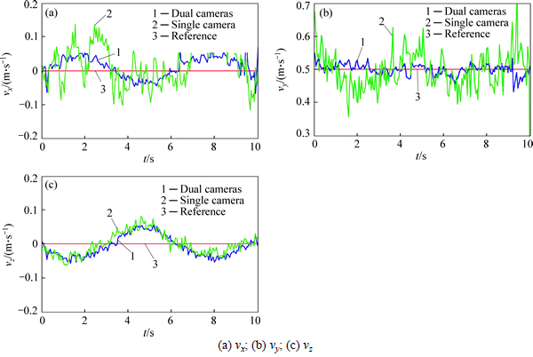
Fig. 9 Translational motion estimation results:
The results show that the impact of rotational motion on the translational velocity estimation could be greatly reduced by using optical flow from dual cameras.
5 Conclusions
The 6-DOF motion estimation method using optical flow from dual cameras is presented in this article. First, rotational velocities and angles are calculated by forward-looking camera motion estimation and used in down-looking camera motion estimation to get translational velocities. By this means, the impact of rotational motion on the translational motion estimation is greatly reduced. Then, the computation amount is cut down by adopting a simplified translational motion model. In conclusion, the method presented takes full use of the visual information of the surrounding environment, and relies on vision sensors only to realize the aircraft��s 6-DOF motion estimation in real time, which can be used in indoor, low altitude and deep space navigation.
References
[1] LU Hui-min, ZHANG Hui, ZHENG Zhi-qiang. A review of vision-based mobile robot��s self-localization [J]. Journal of Central South University, 2009, 40(S1): 127-133.
[2] CHAO H, GU Y, NAPOLITANO M. A survey of optical flow techniques for robotics navigation applications [J]. Journal of Intelligent & Robotic Systems, 2014, 73(1-4): 361-372. (in Chinese)
[3] LI Jian, LAN Jin-hui, LI Jie. A novel fast moving target detection method [J]. Journal of Central South University, 2013, 44(3): 978-984. (in Chinese)
[4] GRIFFITHS S, SAUNDERS J, CURTIS A, BARBER B, MCLAIN T,BEARD R, Obstacle and terrain avoidance for miniature aerial vehicles [C]// Advances in Unmanned Aerial Vehicles. Netherlands: Springer, 2007: 213-244.
[5] GAGEIK N, STROHMEIER M, MONTENEGRO S. An autonomous uav with an optical flow sensor for positioning and navigation [J]. International Journal of Advanced Robotic Systems, 2013, 10. DOI: 10.5772/56813
[6] LIPPIELLO V, LOIANNO G, SICILIANO B. MAV indoor navigation based on a closed-form solution for absolute scale velocity estimation using optical flow and inertial data [C]// Decision and Control and European Control Conference (CDC-ECC), 2011 50th IEEE Conference on Orlando, US: IEEE, 2011: 3566-3571.
[7] SUN Ke, YUN Yu, ZHOU Wang-cheng, ZHOU Gu-yue. A low-cost and robust optical flow CMOS camera for velocity estimation [C]// Robotics and Biomimetics (ROBIO), 2013 IEEE International Conference on. Shenzhen, China: IEEE, 2013: 1181-1186.
[8] HONEGGER D, MEIER L, TANSKANEN P, POLLEFEYS M. An open source and open hardware embedded metric optical flow CMOS camera for indoor and outdoor applications [C]// Robotics and Automation (ICRA), 2013 IEEE International Conference on. Karlsruhe, Germany: IEEE, 2013: 1736-1741.
[9] MAMMARELLA M, CAMPA G, FRAVOLINI M L, NAPOLITANO M R. Comparing optical flow algorithms using 6-DOF motion of real-world rigid objects [J]. Systems, Man, and Cybernetics, Part C: Applications and Reviews, IEEE Transactions on, 2012, 42(6): 1752-1762.
[10] KEHOE J J , CAUSEY R S, ARVAI A, LIND R. Partial aircraft state estimation from optical flow using non-model-based optimization [C]// American Control Conference, 2006. Minneapolis, USA: IEEE, 2006: 2868-2873.
[11] KEHOE J J, WATKINS A S, CAUSEY R S, LIND R. State estimation using optical flow from parallax-weighted feature tracking [C]// Proceedings of the AIAA Guidance, Navigation, and Control Conference. Keystone, USA: AIAA, 2006: 5030-5045.
[12] KENDOUL F, FANTONI I, NONAMI K. Optic flow-based vision system for autonomous 3D localization and control of small aerial vehicles [J]. Robotics and Autonomous Systems, 2009, 57(6): 591-602.
[13] BAKER S, SCHARSTEIN D, LEWIS J P, ROTH S,BLACK M J, SZELISKI R. A database and evaluation methodology for optical flow [J]. International Journal of Computer Vision, 2011, 92(1): 1-31.
[14] LOWE D G. Distinctive image features from scale-invariant keypoints [J]. International Journal of Computer Vision, 2004, 60(2): 91-110.
[15] LUCAS B D, KANADE T. An iterative image registration technique with an application to stereo vision [J]. IJCAI, 1981, 81: 674-679.
[16] BRANCA A, STELLA E, DISTANTE A. Passive navigation using focus of expansion [C]// Applications of Computer Vision, 1996. WACV'96, Proceedings 3rd IEEE Workshop on Washington D C, USA: IEEE, 1996: 64-69.
[17] FRITSCH J, KUEHNL T, GEIGER A. A new performance measure and evaluation benchmark for road detection algorithms [C]// International Conference on Intelligent Transportation Systems (ITSC). The Hague, Netherlands: IEEE, 2013: 1693-1700.
(Edited by DENG L��-xiang)
Cite this article as:
LIU Meng-yao, WANG Yan, GUO Lei. 6-DOF motion estimation using optical flow based on dual cameras [J]. Journal of Central South University, 2017, 24(2): 459-466.
DOI:https://dx.doi.org/10.1007/s11171-017-3448-xFoundation item: Project(2012CB720003) supported by the National Basic Research Program of China; Projects(61320106010, 61127007, 61121003, 61573019) supported by the National Natural Science Foundation of China; Project (2013DFE13040) supported by the Special Program for International Science and Technology Cooperation from Ministry of Science and Technology of China
Received date: 2015-11-13; Accepted date: 2016-01-13
Corresponding author: GUO Lei, Professor, PhD; Tel: +86-10-82313626; E-mail: lguo@buaa.edu.cn
Abstract: Because of its characteristics of simple algorithm and hardware, optical flow-based motion estimation has become a hot research field, especially in GPS-denied environment. Optical flow could be used to obtain the aircraft motion information, but the six-(degree of freedom) (6-DOF) motion still couldn��t be accurately estimated by existing methods. The purpose of this work is to provide a motion estimation method based on optical flow from forward and down looking cameras, which doesn��t rely on the assumption of level flight. First, the distribution and decoupling method of optical flow from forward camera are utilized to get attitude. Then, the resulted angular velocities are utilized to obtain the translational optical flow of the down camera, which can eliminate the influence of rotational motion on velocity estimation. Besides, the translational motion estimation equation is simplified by establishing the relation between the depths of feature points and the aircraft altitude. Finally, simulation results show that the method presented is accurate and robust.
