
Trans. Nonferrous Met. Soc. China 23(2013) 2833-2842
Comparison of microstructure and mechanical properties of conventional and refilled friction stir spot welds in AA 6061-T6 using filler plate
S. VENUKUMAR, S. YALAGI, S. MUTHUKUMARAN
Department of Metallurgical and Materials Engineering, National Institute of Technology, Tiruchirappalli-620015, Tamil Nadu, India
Received 7 January 2013; accepted 27 March 2013
Abstract:
Friction stir spot welding with refilling by friction forming process (FSSW-FFP) was successfully modified using filler plate. Both of this new refilling technique and conventional friction stir spot welding (FSSW) process were used to weld Al 6061-T6 lap shear specimens and the results were compared. Effects of tool rotational speeds on mechanical and metallurgical properties in both the cases were studied. Static shear strength of refilled weld samples was found to be better than those welded by conventional FSSW process at all tool rotational speeds. This is explained in terms of effective increase in cross-sectional area of weld nugget due to addition of more material from filler plate, thereby eliminating the probe hole. Failure mechanisms were discussed and fracture surfaces were analyzed through scanning electron microscopy (SEM). The hardness profile of the welds exhibited a W-shaped appearance in both the processes and the minimum hardness was measured in the HAZ.
Key words:
AA6061-T6 Al alloy; friction stir spot welding; FSSW-FFP; static shear strength;
1 Introduction
In recent years, aluminum alloys have attracted attention of many researchers, engineers and designers as promising structural materials for automotive industry and aerospace applications [1]. Especially, 6xxx aluminum alloys have been studied extensively because of their benefits such as better strength, formability, corrosion resistance, and low cost compared with other aluminum alloys [2,3].
Friction stir spot welding (FSSW) is a process developed recently and has been studied for applications in automotive, aeronautic and other industries [4]. It is a derivative of the friction stir welding (FSW) process widely used for joining aluminum alloys, with the essential difference that there is no translation of the tool during FSSW [5]. The process can be explained in three distinct steps: plunging, stirring and retracting. The process initiates with the tool plunging slowly, then the combined effects of tool rotation and heating promote the stirring and finally the tool is retracted [6]. The retracting step is performed rapidly, just after the tool has reached the plunge depth or after a specific dwell time [7].
FSSW mentioned above also can be called as plunge friction stir welding (PFSSW) or conventional friction stir spot welding, which was patented by MAZDA in 2003 [8,9]. However, one of the disadvantages of FSSW joint is that probe hole inevitably remaining at the centre of the weld nugget reduces the joint strength and that corrosion could take place preferentially at the probe hole because rainwater remains in the hole, where body paint barely reaches the bottom [10]. There are very few publications about refilling of probe hole during friction stir spot welding process. In order to avoid this, GKSS of Germany invented a process that would fill the key hole and this method was called the refill FSSW process [11]. UEMATSU et al [10] reported that FSSW was performed using a specially designed double-acting tool consisting of outer flat shoulder and inner retractable probe, which could re-fill probe hole of the joints. The results showed that the tensile strength of the joint with re-filled hole was higher than that of the joint with probe hole [10].
The refilling technique developed so far sometimes fails to fully refill the plasticized material in the probe hole thus might result in void formation in the refilled region. The void formed is not visible from outside therefore it is more dangerous to use the process for critical applications such as aerospace [12,13]. Friction forming process was invented by MUTHUKUMARAN and the patent was granted in 2008 [14]. This process is suitable for ductile materials and a desired shape or contour can be achieved by generating heat by friction using a suitable external tool called friction forming tool. Based on the friction forming process, a new friction spot welding process was reported by JOHN PRAKASH and MUTHUKUMARAN [15] known as friction stir spot welding with refilling by friction forming process (FSSW-FFP). They have developed two tools, namely extrusion tool and friction forming tool, in order to refill probe hole during the friction stir spot welding process.
In the present study, in order to increase the volume of metal extruded, the FSSW-FFP is modified by adding an additional plate, called filler plate. The mechanical properties of both conventional FSSW and FSSW-FFP are evaluated and compared. The microstructure, bonded regions and failure mechanisms of both the processes are discussed based on the experimental observations.
2 Experimental
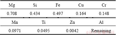
AA 6061-T6 sheets with 2 mm in thickness were chosen for the present study. The chemical composition is listed in Table 1. The work piece length, width and overlapping length were 100 mm, 30 mm and 30 mm, respectively. In order to increase the volume of metal extruded, filler plate was used. Material and composition of the filler plate were the same as these of the work pieces. The volume of the metal extruded from the filler plate will increase the effective cross-sectional area of the weld nugget. Prior to welding, all the sheets were cleaned with acetone to remove any impurities on the surface, such as dirt and oil. The welds were made by a modified milling machine and a fixture was designed for friction stir spot welding of specimens. In conventional FSSW, tool consists of a shoulder of 18 mm in diameter and a pin of 5 mm in diameter. In FSSW-FFP, two types of tools, namely extrusion tool and friction forming tool, both made from heat treated EN 31 series high carbon steel were used. Extrusion tool was similar to the conventional FSSW tool but the pin length was more. Friction forming tool consisted of shoulder of 18 mm in diameter and was used for the refilling process. Four different tool rotational speeds, namely 900, 1120, 1400 and 1800 r/min, were chosen and test was repeated three times at each speed for both the processes [16].
The schematic representation of the FSSW-FFP is shown in Fig. 1. This process involved basically two steps, namely extrusion and refilling. The three plates (one filler plate and two work pieces) were placed one above the other and this whole assembly was placed on a backing plate. First step involved forcing a rotating tool through a sheet metal work piece. The frictional heating at the interface between the tool and work piece enabled the softening, deformation, and displacement of work material and created a bushing projection in the bottom plate, leaving behind a probe hole in the top plate, as shown in Fig. 1(c). The tool was lowered and suitable plunge depth was given as soon as shoulder touched the filler plate. Once the shoulder crossed the filler plate, the filler plate was separated from the assembly. This was followed by reversal of the remaining two plates for refilling operation. In the second step, namely refilling, the bush type material which had come out during the first step was plunged back by friction forming tool, as shown in Figs. 1(c) and (d). Thus the bush-shaped projection when plunged helps refilling the probe hole produced during extrusion.
Macrostructural study was carried out by optical microscopy for getting different regions of friction stir spot welded specimen. For observation of weld macrostructures, specimens were etched with the Tucker��s reagent (3 mL HNO3, 9 mL HCL, 3 mL HF and 5 mL water). The etchant time used was 15-20 s. Microstructural studies were carried out by optical microscope and specimens were etched with the Keller��s reagent (1 mL HF, 1.5 mL HCl, 2.5 mL HNO3 and 9.5 mL H2O) and the etching time used was 15-20 s. The Vickers microhardness test was performed on the cross-section of the FSSW samples using a 4.9 N load for 20 s to obtain the hardness profiles.
Table 1 Chemical composition (mass fraction, %) of 6061-T6Al alloy sheets used in this work
The lap shear samples were prepared according to the dimensions shown in Fig. 2. They were tested by a tensile testing machine at a monotonic displacement rate of 0.01 mm/s. The load and displacement were simultaneously recorded during the test. The lap shear strength was obtained by averaging the strengths of three individual specimens which were welded with identical welding parameters. Fracture surfaces of specimens were observed using a scanning electron microscope.
3 Results and discussion
Figure 3 shows the top view and macroscopic appearance of a cross-section of the welds made by conventional FSSW, at a rotational speed of 900 r/min.

Fig. 1 Schematic illustration of FSSW-FFP
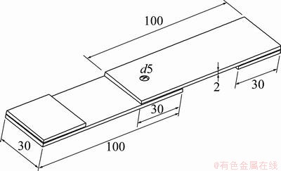
Fig. 2 Schematic representation of lap shear specimen (unit: mm)
Figure 4 shows the close-up views of the regions A, B, and C marked in Fig. 3(b). In the present study, according to the characteristic of the cross-section of the FSSW joint, the cross-section is divided into three regions A, B, and C which are stir zone (SZ), thermo- mechanically affected zone (TMAZ), and the base material (BM), respectively. Heat affected zone is also present which cannot be resolved with optical microscope but can be identified by analyzing microhardness [17].
More grain refinement is observed in SZ and TMAZ compared with BM due to stirring action. Since region A is adjacent to the keyhole, most of the stirring action takes place in this region. The grains in this region are subjected to high plunging action and undergo dynamic recrystallization due to combined effect of high temperature produced by frictional heat and stirring action. Hence, very fine equiaxed grains with the average grain size of 12 ��m are obtained and this region is defined as the SZ. Grains in the vicinity of tool shoulder are deformed and elongated due to mechanical stirring of tool and grain refinement is also observed in the region B. The average grain size observed in this region is 17 ��m which is coarser than SZ and finer than BM. This region is defined as TMAZ. Figure 4(c) shows the microstructure of the base material (BM) which has average grain size of 27 ��m [18]. Figure 5(a) shows the macrostructure of joint interface. The magnified view of region a1 in Fig. 5(a) is shown in Fig. 5(b) in order to study the material flow pattern at the boundary of the interface. Figure 5(b) shows that material from the lower sheet flows in upward direction and finally disappears near the stir zone.

Fig. 3 Macroscopic appearance of conventional FSSW joint
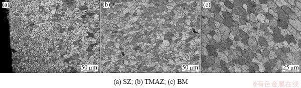
Fig. 4 Microstructures of conventional FSSW joint
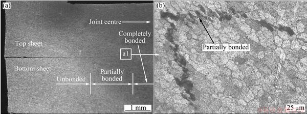
Fig. 5 Macrostructure of different bonding regions in conventional FSSW joint
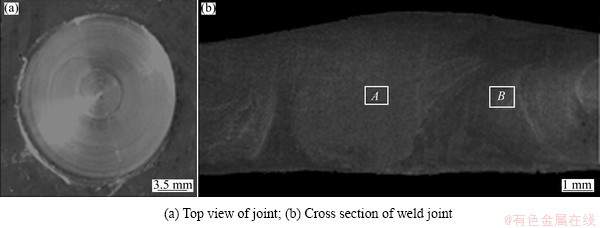
Fig. 6 Macroscopic appearance of FSSW-FFP joint
Figure 6 shows the top view and macroscopic appearance of a cross-section of the welds made by FSSW-FFP, at a rotational speed of 1800 r/min. It is clear that probe hole is successfully refilled by FSSW-FFP. Figure 7 shows the close-up views of the regions A and B marked in Fig. 6(b) which are stir zone (SZ) and thermo- mechanically affected zone (TMAZ), respectively. The average grain sizes in SZ and TMAZ are 16 ��m and 10 ��m respectively, indicating that the grains in SZ are slightly coarser than those of the joint with probe hole, which can be attributed to the heat input into SZ during re-filling process [10]. Figure 8 shows the material flow pattern at the boundary of the interface. It can be seen that the upward flow of material is arrested due to the flat face of friction forming tool. Material flow is almost horizontal and eventually disappearing near stir zone.
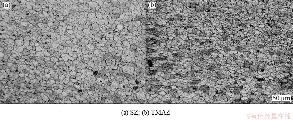
Fig. 7 Microstructures in FSSW-FFP samples
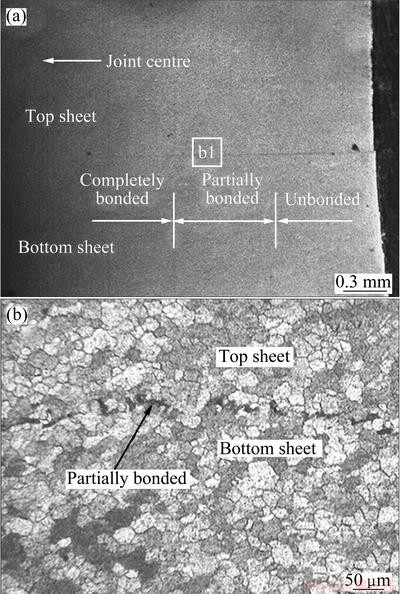
Fig. 8 Macrostructure of different bonding regions in conventional FSSW-FFP sample
3.1 Microhardness test
In order to understand the hardness variation in different regions of the friction stir spot welds, hardness data across the SZ, TMAZ and BM are noted. The indentations were made with a spacing of 0.4 mm along each of the four parallel lines. The Vickers hardness profiles of the conventional FSSW and FSSW-FFP joints made at rotational speed of 900 and 1800 r/min are represented in Fig. 9. In conventional FSSW joints hardness in SZ is high and gradually decreases through TMAZ and reaches a minimum value and again increases towards base material exhibiting W shape appearance. This region where hardness is minimum can be identified as HAZ. The region between TMAZ and HAZ is the softest region. Loss of hardness in HAZ is due to over aging in which coarsening of precipitates takes place. SZ is associated with very high temperature and severe plastic deformation as mentioned previously which leads to dynamic recrystallization and fine grain structure. Large precipitates at such high temperature get dissolved and very fine precipitates form. Thus, hardness increase in SZ is due to the fine grains and fine precipitates. In refilled weld samples similar W shape hardness profile is also obtained. But hardness decrease in HAZ of refilled samples is lesser than that of conventional FSSW samples.
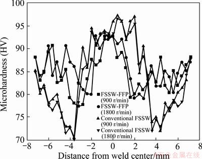
Fig. 9 Hardness profiles of conventional FSSW and FSSW-FFP joints across weld interface
3.2 Tensile/shear tests
Static shear strengths of the welds made by conventional FSSW and FSSW-FFP techniques are compared. It is found that the welds made by FSSW-FFP show higher static shear strengths than that by conventional FSSW process, as shown in Fig. 10. The increase in static shear strength in FSSW-FFP technique is attributed to the absence of keyhole and also the presence of extra material in the weld due to filler plate addition. The extra material from the filler present in the joint will create more compact pressure leading to increased bond length, thus enhancing the static shear strength. While the keyhole present in conventional technique acts as notch during loading and causes excessive stress concentration. This would lead to the initiation and propagation of the crack, leading to poor mechanical properties. It can be observed from Fig. 10 that by FSSW-FFP better static shear strength can be achieved at a rotational speed of 1800 r/min, while by conventional FSSW process better static shear strength was achieved at 900 r/min. The improvement in static shear strength by FSSW-FFP is found to be 38.5% higher than that by conventional FSSW.
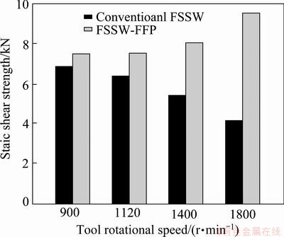
Fig. 10 Static shear strength of FSSW joints under different rotational speeds
In the above two processes, the bonding conditions between two sheets can be categorized as completely bonded region, partially bonded region and unbonded region as shown in Figs. 5 and 8. In completely bonded region, the joint interface between two sheets surfaces cannot be identified, which indicates that they are completely metallurgically bonded. Most of the stirring action takes place in this region, due to which grains from both the sheets are effectively mixed [19]. Joint interface below the tool axis and just at the periphery of tool pin falls into this category. Joint interface below tool shoulder is categorized into partially bonded region where non uniform mixing has been observed due to uneven heating. However, joint interface at some parts in this region is found to be mechanically bonded due to tool shoulder pressure (Fig. 5(b) and Fig. 8(b)). In unbonded region neither stirring action takes place nor there is mechanical pressure due to tool shoulder because of which there is no bond. This region is away from tool and is near at the end of sheets. By conventional FSSW process, the length of completely bonded region at 900 r/min is 4.6 mm and at 1800 r/min is 1.5 mm. By FSSW-FFP, the length of completely bonded region at 900 r/min is 4.9 mm and at 1800 r/min is 8.4 mm. Based on the above values, it can be concluded that by conventional FSSW better static shear strength is obtained at 900 r/min and by refilling process at 1800 r/min better strength is obtained as explained in previous section.
Figure 11 shows different fracture modes of failure in both the processes. Shear fracture mode of failure is observed in conventional FSSW weld samples at all speeds. Three different types of fracture modes are observed in refilled process. They fracture in base material, circumferential fracture and nugget pull out fracture. Irrespective of fracture mode crack initiation always starts at the partial bonding region. This region offers several nucleation sites where a crack can initiate. As the tensile load on weld sample increases, crack propagates through completely bonded region. When enough load is applied, tearing of crack takes place, thereby breaking the bond between sheets. In shear fracture, material gets sheared off at the periphery of probe hole due to tearing action, as shown in Fig. 12(a). In refilled samples, tearing leads to different modes of fracture. Due to tearing, crack may propagate along the circumference of weld nugget, which eventually leads to circumferential fracture, or crack may propagate vertically in upper or lower sheets, leading to weld nugget pull out, as shown in Fig. 12(b). Hook also plays very important role in the propagation of crack. It is formed due to outward flow of material during plunging and if it is very sharp, it can act as nucleation site [20]. Crack propagation in the lower sheet is mainly due to non uniform mixing or incomplete refilling. Excessive plunge depth at higher tool rotation speeds creates a wedge at joint interface and the tip of this wedge can act as nucleation site. Thus, it has been observed that the crack always initiates at partially bonded region and propagates in different ways, reducing the effective bond area, leading to different modes of fracture. In base material fracture mode, weld nugget is stronger than the base material, thus fracture takes place at base material only. Hence it has been considered that weld samples with base material fracture mode have better static shear strength than these with other modes of fracture.
3.3 SEM analysis
Figure 13 shows SEM images of a fracture surface in conventional FSSW specimen welded at the tool rotational speed of 900 r/min. Figure 13(a) reveals the macroscopic fracture surface of the close-up top view of the lower sheet. It can be clearly recognized that shear fracture has taken place along the boundary between the upper and lower sheets along the periphery of the probe hole, and the faying surface between the two sheets has been completely sheared off. Figures 13(b), (c) and (d) reveal the magnified views of the regions in Fig. 13(a) respectively. The crack is initiated in the region A, which corresponds to partially bonded region where considerable variation of hardness can be observed. In this region, very few dimples are observed where crack has initiated and propagated along the periphery of probe hole. The fracture surfaces shown in regions B and C exhibit more elongated dimples of various sizes in the same direction. The presence of elongated dimples indicates the shear fracture at the final stage of failure [21,22].
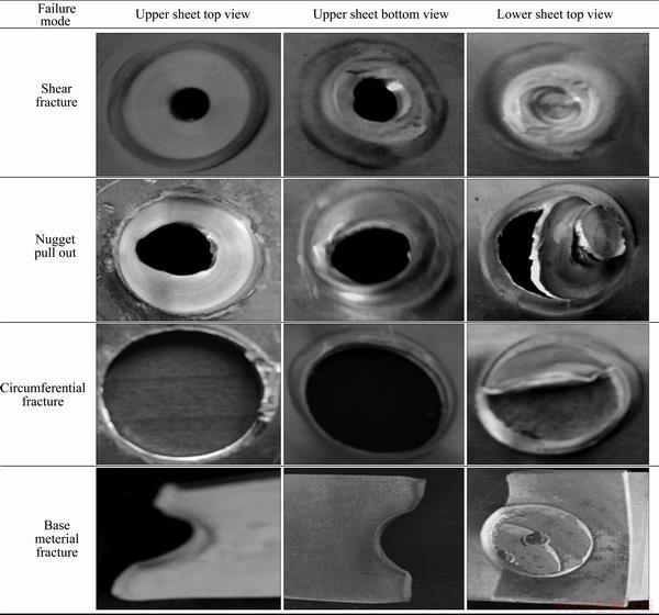
Fig. 11 Macroscopic appearances of different modes of fracture
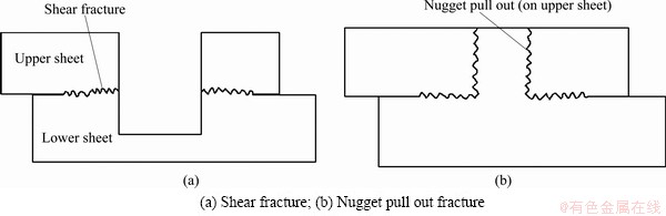
Fig. 12 Schematic illustration showing fracture path
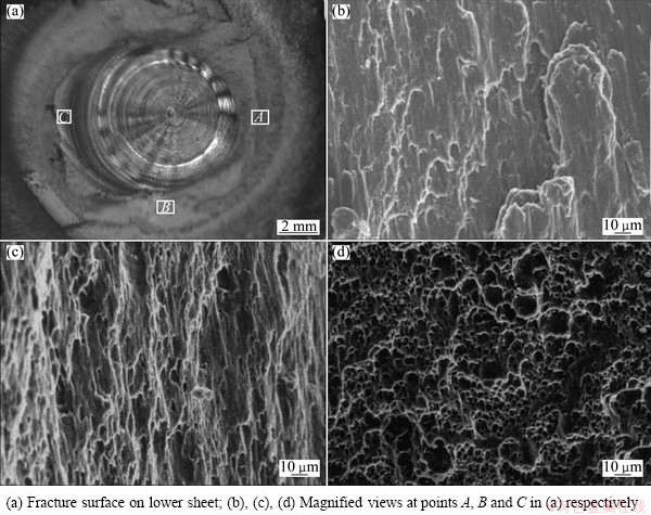
Fig. 13 SEM images of fracture surfaces in conventional FSSW sample
Figure 14 shows SEM images of fracture surfaces in FSSW-FFP specimen welded at the tool rotational speed of 1800 r/min. Figure 14(a) shows the whole view of base material fracture and Figs. 14(a1), (b1) and (c1) show the magnified views of the regions marked in Fig. 14(a). Figures 14(a2), (b2) and (c2) are magnified views of the regions marked in Figs. 14(a1), (b1) and (c1) respectively. These regions show more number of equiaxed dimples compared with conventional FSSW samples, which indicates the better bonding between the upper and lower sheets. Therefore, the static strength is better in the refilled samples compared with conventional samples.
4 Conclusions
1) The draw backs of probe hole are overcome by adopting the new refilling technique, leading to enhanced mechanical properties of the joint.
2) Grain refinement is observed in SZ and TMAZ regions due to dynamic recrystallization.
3) Both the processes exhibit similar W shape hardness profile. HAZ is identified as the region with a minimum hardness value.
4) FSSW-FFP samples have shown better static shear strength than conventional FSSW samples. The increase in static shear strength in FSSW-FFP technique is attributed to the absence of keyhole and also the presence of extra material in the weld due to filler plate addition.
5) The static shear strength obtained by FSSW-FFP at the speed of 1800 r/min is 9520 N and this value is 38.5% higher than that by conventional FSSW process.
6) Shear fracture was observed only in conventional FSSW samples. Three different types of fractured modes, namely circumferential fracture, nugget pull out and base material fracture, are observed in FSSW-FFP samples. Crack initiation always starts in partially bonded region in all modes of fracture.
Acknowledgements
The authors wish to express their sincere thanks to the Ministry of Human Resource Development (MHRD), Government of India, for the financial support to carry out this investigation.
The valuable comments of the anonymous reviewers in improving the manuscript are thankfully acknowledged.
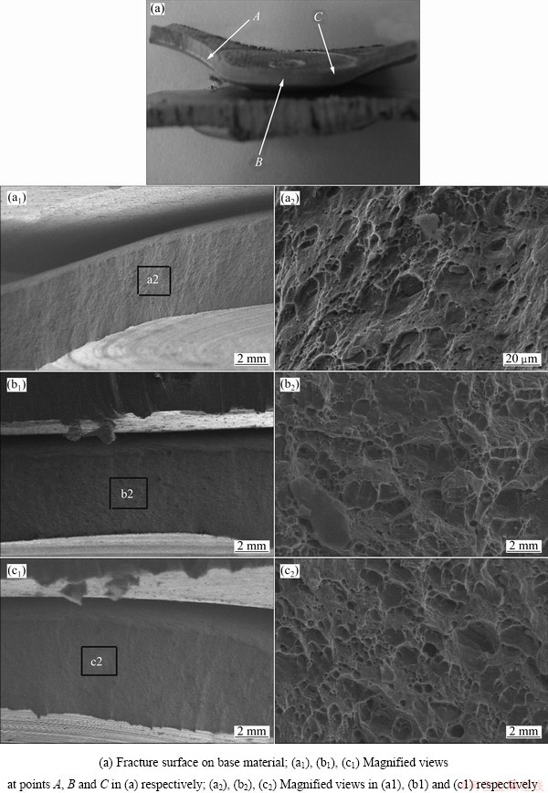
Fig. 14 SEM images of fracture surfaces in FSSW-FFP sample
References
[1] TROEGER L P, STARKE E A Jr. Microstructural and mechanical characterization of a superplastic 6xxx aluminum alloy [J]. Materials Science and Engineering A, 2000, 277: 102-113.
[2] LEE S H, SAITO Y, SAKAI T, UTSUNOMIYA H. Microstructures and mechanical properties of 6061 aluminum alloy processed by accumulative roll-bonding [J]. Materials Science and Engineering A, 2002, 325: 228-235.
[3] MANSOURINEJAD M, MIRZAKHANI B. Influence of sequence of cold working and aging treatment on mechanical behaviour of 6061 aluminum alloy [J]. Transactions of Nonferrous Metals Society of China, 2012, 22: 2072-2079.
[4] HANCOCK R. Friction welding of aluminum cuts energy cost by 99% [J]. Welding Journal, 2004, 83: 40-45.
[5] LATHABAI S, PAINTER M J, CANTIN G M D, TYAGI V K. Friction spot joining of an extruded Al-Mg-Si alloy [J]. Scripta Materilia, 2006, 55: 899-902.
[6] AWANG M, MUCINO V H, FENG Z, DAVID S A. Thermo-mechanical modeling of friction stir spot welding (FSSW) process: Use of an explicit adaptive meshing scheme [J]. SAE International, 2005, 45: 1577-1587.
[7] MALAFAIA A M S, MILAN M T, OLIVEIRA M F, SPINELLI D. Fatigue behavior of friction stir spot welding and riveted joints in an Al alloy [J]. Procedia Engineering, 2010, 2(1): 1815-1821.
[8] BADARINARAYAN H, HUNT F, OKAMOTO K. Friction stir welding and processing [M]. Novelty, OH: ASM International, 2007: 235-272.
[9] IWASHITA T. Method and apparatus for joining: US6601751B2 [P]. 2003-08-05.
[10] UEMATSU Y, TOKAJI K , TOZAKI Y, KURITA T, MURATA S. Effect of re-filling probe hole on tensile failure and fatigue behavior of friction stir spot welded joints in Al-Mg-Si alloy [J]. International Journal of Fatigue, 2008, 30: 1956-1966.
[11] SHILLING C, DOS SANTOS J. Method and device for joining at least two adjoining work pieces by friction welding: US0179682 [P]. 2002-12-05.
[12] MISHRA R S, MA Zong-yi. Friction stir welding and processing [J]. Material Science and Engineering R, 2005, 50(1-2): 1-78.
[13] BUFFA G, FRATINI L, PIACENTINI M. On the influence of tool path in friction stir spot welding of aluminum alloys [J]. Journal of Materials Processing Technology, 2008, 208(1-3): 309-317.
[14] MUTHUKUMARAN S. An improved friction forming process and a friction forming machine with a tool and fixture: Indian, application No.137/KOL/06 (filed on 16-02-2006), Patent No.242420 [P]. 2010-08-27.
[15] JOHN PRAKASH S, MUTHUKUMARAN S. Refilling probe hole of friction spot joints by friction forming [J]. Materials and Manufacturing Process, 2011, 26: 1539-1545.
[16] GERLICH A, YAMAMOTO M, NORTH T H. Strain rates and grain growth in Al 5754 and Al 6061 friction stir spot welds [J]. Metallurgical and Materials Transactions A, 2007, 38: 1291-1302.
[17] ROSENDO T, PARRA B, TIER M A D, DA SILVA A A M, DOS SANTOS J F, STROHAECKER T R. Mechanical and microstructural investigation of friction spot welded AA 6181T4 aluminium alloy [J]. Materials and Design, 2011, 32: 1094-1100.
[18] RAJAKUMAR S, MURALIDHARAN C, BALASUBRAMANIAN V. Establishing empirical relationships to predict grain size and tensile strength of friction stir welded AA 6061-T6 aluminium alloy joints [J]. Transactions of Nonferrous Metals Society of China, 2010, 20: 1863-1872.
[19] MITLIN D, RADMILOVIC V, PAN T, CHEN J, FENG Z, SANTELLA M L. Structure-properties relations in spot friction welded (also known as friction stir spot welded) 6111 aluminum [J]. Materials Science and Engineering A, 2006, 441(1-2): 79-96.
[20] BADARINARAYAN H, YANG Q, ZHU S. Effect of tool geometry on static strength of friction stir spot-welded aluminum alloy [J]. International Journal of Machine Tools & Manufacture, 2009, 49: 142-148.
[21] SHEN Zhi-kang, YANG Xin-qi, ZHANG Zhao-hua, CUI Lei, LI Tie-long. Microstructure and failure mechanisms of refill friction stir spot welded 7075-T6 aluminum alloy joints [J]. Materials and Design, 2013, 44: 476-486.
[22] ZHANG Zhao-hua, YANG Xin-qi, ZHANG Jia-long, ZHOU Guang, XU Xiao-dong, ZOU Bin-lian. Effect of welding parameters on microstructure and mechanical properties of friction stir spot welded 5052 aluminum alloy [J]. Materials and Design, 2011, 32: 4461-4470.
�������Ħ���㺸�ʹ�ͳ����Ħ���㺸AA6061-T6��ͷ���۽ṹ����ѧ���ܵıȽ�
S. VENUKUMAR, S. YALAGI, S. MUTHUKUMARAN
Department of Metallurgical and Materials Engineering, National Institute of Technology, Tiruchirappalli-620015, Tamil Nadu, India
ժ Ҫ���ڽ���Ħ���㺸�����У�ͨ����������������Ħ�����ι��̣������¹��ձ���Ϊ�������Ħ���㺸���ֱ���û������Ħ���㺸�ʹ�ͳ�Ľ���Ħ���㺸���պ���AA6061-T6��Ӻ���Ʒ���о�����ͷ����ת�ٶȶԽ�ͷ����ѧ���ܺͽ�����֯��Ӱ�졣�ڲ�ͬ����ת�ٶ��£��������Ħ���㺸��ͷ�ľ�̬����ǿ�ȶ��ȴ�ͳ����Ħ���㺸��ͷ�ĺá���������ڻ������Ħ���㺸ʱ������������Ӷ��и���IJ������������������γɵĿ�ȱ�ݣ��Ӷ�ʹ�㺸����������Ч��������ӡ�����ɨ��羵�۲������˲��ϵ�ʧЧ���ƣ������˶��ѱ�����ò��2�ֺ��ӽ�ͷ��Ӳ�����߶���W�Σ���С��Ӳ�ȳ�������Ӱ������
�ؼ��ʣ�AA 6061-T6 ���Ͻ𣻽���Ħ���㺸���������Ħ���㺸����̬����ǿ��
(Edited by Hua YANG)
Corresponding author: S. MUTHUKUMARAN; Tel: +91-9442069381; Fax: 91-431-2500133; E-mail: pondymuthu@gmail.com
DOI: 10.1016/S1003-6326(13)62804-6
Abstract: Friction stir spot welding with refilling by friction forming process (FSSW-FFP) was successfully modified using filler plate. Both of this new refilling technique and conventional friction stir spot welding (FSSW) process were used to weld Al 6061-T6 lap shear specimens and the results were compared. Effects of tool rotational speeds on mechanical and metallurgical properties in both the cases were studied. Static shear strength of refilled weld samples was found to be better than those welded by conventional FSSW process at all tool rotational speeds. This is explained in terms of effective increase in cross-sectional area of weld nugget due to addition of more material from filler plate, thereby eliminating the probe hole. Failure mechanisms were discussed and fracture surfaces were analyzed through scanning electron microscopy (SEM). The hardness profile of the welds exhibited a W-shaped appearance in both the processes and the minimum hardness was measured in the HAZ.
