
Trans. Nonferrous Met. Soc. China 24(2014) 3051-3059
Vacuum assisted high-pressure die casting of AZ91D magnesium alloy at different slow shot speeds
Qing-liang WANG1,2, Shou-mei XIONG1,2
1. School of Materials Science and Engineering, Tsinghua University, Beijing 100084, China;
2. State Key Laboratory of Automobile Safety and Energy, Tsinghua University, Beijing 100084, China
Received 21 October 2013; accepted 27 January 2014
Abstract:
The effects of vacuum assistance on the microstructure and mechanical properties of high-pressure die cast AZ91D alloy at different slow shot speeds were evaluated. Plate-shaped castings of AZ91D alloy were carried out on a TOYO BD-350V5 cold chamber die casting machine incorporated with a self-improved TOYO vacuum system. It was found that the vacuum pressure in the die cavity at the beginning of mold filling increases with the increase of slow shot speed, following a cubic polynomial curve, resulting in a decline in the porosity-reduction ability of vacuum assistance with the increase of slow shot speed. The externally solidified crystal (ESC) contents in conventional and vacuum die castings behave similar against the slow shot speed. The tensile properties of vacuum die castings were strongly influenced by the ESC content at relative low slow shot speeds. With the increase of slow shot speed, the influence of the gas porosity level in vacuum die castings would get prominent.
Key words:
vacuum die casting; slow shot speed; porosity; externally solidified crystals;
1 Introduction
High-pressure die casting is one of the most commonly used molding methods for magnesium and aluminum alloys. During this process, gas porosity would be formed in the produced castings mainly due to the entrapment of air in the molten metal as a consequence of the high speed injection of the molten metal into the die cavity. The presence of gas porosity in castings is harmful because the mechanical properties, weldability and pressure tightness are adversely affected [1,2].
Vacuum die casting is an effective way in reducing the gas porosity level in castings. By creating a lower atmospheric pressure in the shot sleeve and die cavity, much less gas would be entrapped in the molten metal during the vacuum die casting process. At the same time, the back pressures encountered by the molten metal trying to fill die cavity are reduced, which makes the production of thin wall castings of large area available. Besides, the vacuum die casting process is simple, easy to operate and with almost the same production efficiency as the conventional die casting process. For all these advantages, the vacuum die casting process has been widely applied to the die casting industry [3].
The vacuum pressure in the die cavity at the beginning of mold filling has a great influence on the quality of vacuum die castings. In order to enhance the evacuating ability of the vacuum system, equipment techniques, such as the designing of vacuum valve [3] and the mold sealing technique [4], have achieved considerable attention. An ultra-high vacuum level of 5-10 kPa can now be achieved. The volume of gas porosity in castings can be significantly reduced while filling the die cavity with such high vacuum levels [5,6]. Compared with the massive work on the vacuum systems, little attention has been paid to the effects of casting parameters in the vacuum die casting process. Slow shot speed determines the vacuum time before mold filling, and thus can influence the vacuum pressure in the die cavity at the beginning of mold filling. Meanwhile, the gas entrapment [7-11] and formation of externally solidified crystals (ESCs) [12-14] in the shot sleeve strongly depend on the slow shot speed as it can affect the flow behavior and solidification condition of the molten metal in the shot sleeve before the high speed injection taking place. Consequently, to maximize functionality in a vacuum system, it is extremely important to determine an optimum slow shot speed. The aim of the present work is, therefore, to investigate the effects of the slow shot speed on vacuum pressure in the die cavity at the beginning of mold filling and performance of the produced castings, including the mechanical properties and distribution of gas porosity and ESCs.
2 Experimental
The nominal composition of AZ91D magnesium alloy used in this work is given in Table 1. The experiments were performed on a TOYO BD-350V5 cold chamber die casting machine incorporated with a self-improved TOYO vacuum system. A KEYENCE pressure sensor with the accuracy of 0.1 kPa was mounted on the vacuum pipe installed on the top of the vacuum valve half on the fixed die half, as shown in Fig. 1. The vacuum pressure variation in the die cavity before mold filling can thus be measured as the vacuum pipe connects with the die cavity. Figure 2 shows the configuration of the plate-shaped castings made on the machine. The thicknesses of the six plates in the casting are 6.25, 3.75, 1.25, 2.5, 5.0 and 7.5 mm from left to right. Six slow shot speeds of 0.05, 0.10, 0.15, 0.20, 0.30 and 0.40 m/s were used in the experiments. Die casting was conducted with or without the vacuum assistance for comparison.
Table 1 Nominal chemical composition of AZ91D magnesium alloy (mass fraction, %)

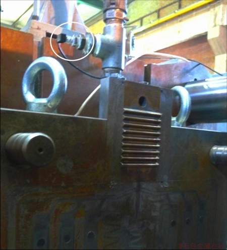
Fig. 1 Mounting position of pressure sensor
Table 2 lists some other important process parameters used in the experiments. The plates with thickness of 3.75 mm in the castings produced at the slow shot speeds ranging from 0.10 to 0.40 m/s were taken as specimens for further analysis (the castings produced at the slow shot speed of 0.05 m/s were not fully filled).
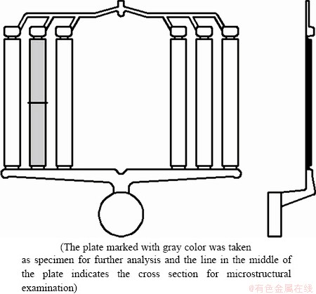
Fig. 2 Configuration of plate-shaped casting with investigated position indicated
Table 2 Process parameters used in die casting

Five specimens for each condition were used to measure the tensile properties. Tensile testing samples were machined based on the Chinese standard GB/T 228.1-2010 with dimensions shown in Fig. 3. Tensile testing was then performed on a WDW-2050 machine at a crosshead speed of 0.5 mm/min, with an extensometer (25 mm in gage length) attached. Some of the remaining specimens were sectioned in the middle for microstructural examination (Fig. 2). The sections were polished using standard metallographic techniques and etched with an acetic nitric etch. Micrographs were taken at the middle of the sections with a Zeiss microscope. Measurements of gas porosity and ESCs were performed using the Micro-image Analysis & Process image analysis software at 25�� and 100�� magnifications, respectively. At least three micrographs were analyzed for each measurement.

Fig. 3 Dimensions of tensile testing samples (unit: mm)
3 Results and discussion
3.1 Effect of slow shot speed on vacuum pressure in die cavity at beginning of mold filling
Figure 4 shows the variations of the measured vacuum pressure and cylinder pressure during the vacuum die casting processes at slow shot speeds of 0.10 and 0.40 m/s, where t and p indicate the vacuum time and vacuum pressure in the die cavity at the beginning of mold filling, respectively. The subscripts 0.10 and 0.40 identify the slow shot speeds used in the vacuum die casting processes. As shown in Fig. 4, the vacuum pressure in the die cavity at the beginning of mold filling strongly depends on the vacuum time. An increase in the vacuum time results in the decrease of the vacuum pressure in the die cavity at the beginning of mold filling until reaching a minimum value.

Fig. 4 Measured vacuum pressure and cylinder pressure variations against plunger moving time at slow shot speeds of 0.10 m/s and 0.40 m/s
The vacuum pressures in the die cavity at the beginning of mold filling at different slow shot speeds are shown in Fig. 5. High vacuum levels of nearly 10 kPa can be achieved in the die cavity at the beginning of mold filling at the slow shot speeds of 0.05 m/s and 0.10 m/s. An increase in the slow shot speed leads to an increase in the vacuum pressure. The measured data can be well fitted by a cubic polynomial curve, as shown in Fig. 5. It indicates that the variation of the vacuum pressure in the die cavity at the beginning of mold filling against the slow shot speed follows the cubic polynomial expression.

Fig. 5 Vacuum pressure in die cavity at the beginning of mold filling at different slow shot speeds
3.2 Casting defects
Figures 6-8 show the typical micrographs from the middle of the section in specimens taken from the conventional and vacuum die castings produced at slow shot speeds of 0.10, 0.20 and 0.40 m/s, respectively. The black nearly spherical feature in the micrographs is the gas porosity. The bands located between the center and outer surfaces of the castings are defect bands. The gas pores located in the defect bands generally have lower degrees of roundness compared with others. This phenomenon can be clearly observed in Fig. 9, which shows the microstructure of a region containing a defect band from Fig. 6(a) at a higher magnification. The formation of the defect bands has not been sufficiently understood. A concept of dilatant shear bands in solidifying alloys [15-17] was recently proposed to explain the formation of defect bands. It was deduced that solidifying alloys with solid fraction (fs) above the dendrite coherency  behave similar to liquid- saturated granular materials, such as water-saturated particulate soils. During shear in both cases, particles lever another apart at their contacts and increase the space between them (dilatancy). Dilatant shear bands where the local fs is lower than adjacent regions thus formed. In the case of solidifying alloys, the dilatant shear bands contain a higher liquid fraction and, therefore, there is a higher solute content (positive macrosegregation) than adjacent regions. In the solidification process, shrinkage porosity is prone to form in the dilatant shear bands as the bands reach the end of solidification later than adjacent regions. As a result, the defect bands always contain a higher fraction of shrinkage porosity than the adjacent regions, as shown in Fig. 9.
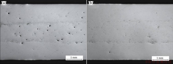
Fig. 6 Typical micrographs from middle of section in specimens produced at slow shot speed of 0.10 m/s, showing porosity distribution and defect bands in conventional (a) and vacuum (b) die castings

Fig. 7 Typical micrographs from middle of section in specimens produced at slow shot speed of 0.20 m/s, showing porosity distribution and defect bands in conventional (a) and vacuum (b) die castings
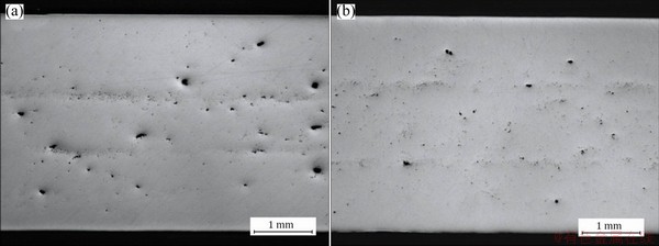
Fig. 8 Typical micrographs from middle of section in specimens produced at slow shot speed of 0.40 m/s, showing porosity distribution and defect bands in conventional (a) and vacuum (b) die castings

Fig. 9 Optical micrograph showing region containing defect band from Fig. 6(a) (Band edges are marked by dotted lines)
Figures 6-8 also show that the vacuum assistance indeed benefits to reduce gas porosity, and the porosity-reduction ability of vacuum assistance varies with the slow shot speed. The measured average area fractions of the gas porosity in the conventional and vacuum die castings produced at different slow shot speeds are displayed in Fig. 10. Only the gas pores larger than 10 ��m in diameter were considered in the measurement to avoid the resolution problem at 25�� magnification and the influence of shrinkage porosity. It is reasonable since the smaller gas pores take only a small part in the total volume of the gas porosity in the castings. As shown in Fig. 10, the gas porosity level in vacuum die castings increases with the increase of slow shot speed. The average area fractions of gas porosity in the vacuum die castings produced at the slow shot speeds of 0.30 m/s and 0.40 m/s are greater than those in the vacuum die castings produced at lower slow shot speeds. This result is probably due to the decreasing vacuum level in the die cavity at the beginning of mold filling with the growth of the slow shot speed, as shown in Fig. 5. Figures 6(a), 7(a) and 8 demonstrate that the gas pores are randomly distributed in the central region broader than that between the defect bands. Surface layers that contain slight gas porosity are found in the castings.

Fig. 10 Measured average area fraction of gas porosity in conventional and vacuum die castings produced at different slow shot speeds
3.3 Effect of slow shot speed on distribution of ESCs
Figures 11 and 12 show the typical micrographs from the middle of the section in specimens taken from the conventional and vacuum die castings produced at different slow shot speeds. Figure 13 shows a higher magnified micrograph obtained from the specimens in vacuum die castings produced at the slow shot speed of 0.15 m/s. The white phases in the micrographs are ��-Mg containing the ones formed in the die cavity and ESCs formed in the shot sleeve. The ��-Mg particles formed in the die cavity are generally smaller than the ESCs formed in the shot sleeve because the cooling rate of the molten metal gets much higher after being transferred from the shot sleeve to the die cavity. In the measurement the ��-Mg particles larger than 7 ��m in diameter were taken as ESCs. The average area fractions of ESCs are displayed in Fig. 14. It can be seen that the vacuum assistance has no strong influence on the ESCs content in the produced castings, and the average area fractions of the ESCs in conventional and vacuum die castings behave similarly against the slow shot speed. The average area fractions firstly decrease when the slow shot speed increases from 0.10 to 0.15 m/s, and then increase when the slow shot speed increases from 0.15 to 0.20 m/s. With further increase of the slow shot speed, the average area fractions would decrease. At the slow shot speeds of 0.10 m/s and 0.20 m/s, the average area fractions of the ESCs in the produced vacuum die castings are both close to 23%, and the average area fractions in the produced conventional die castings are approximately 21% and 22%, respectively. The average area fractions of the ESCs in the conventional and vacuum die castings produced at other three slow shot speeds are much lower.

Fig. 11 Typical micrographs from middle of section in specimens showing distribution of ESCs in conventional die castings produced at slow shot speeds of 0.10 m/s (a), 0.15 m/s (b), 0.20 m/s (c), 0.30 m/s (d) and 0.40 m/s (e)

Fig. 12 Typical micrographs from middle of section in specimens showing distribution of ESCs in vacuum die castings produced at slow shot speeds of 0.10 m/s (a), 0.15 m/s (b), 0.20 m/s (c), 0.30 m/s (d) and 0.40 m/s (e)

Fig. 13 Typical micrograph of specimen in vacuum die casting produced at slow shot speed of 0.15 m/s
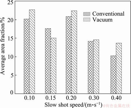
Fig. 14 Measured average area fractions of ESCs in conventional and vacuum die castings produced at different slow shot speeds
The ESCs in the castings originate from the floating crystals formed in the shot sleeve [12,13]. When the liquid metal enters the shot sleeve, it starts to solidify as a result of the heat extraction through the sleeve interface. During the growth of the solid at the wall, a constitutionally undercooled zone is established adjacent to the growing interface, where equiaxed crystals can be formed. As turbulence and convective currents are present in the shot sleeve during the movement of the plunger, some growing dendrites at the wall are fragmented. The fragmented dendrites can be transported from the sleeve wall into the bulk of the liquid metal together with the generated equiaxed crystals. The mixture of floating crystals and liquid is finally forced into the runner system and die cavity during the fast shot phase.
Given the formation mechanism of floating crystals mentioned above, the content of floating crystals in the mixture is determined by two factors: flow behavior and solidification condition of the liquid metal in the shot sleeve. These factors can be affected by the slow shot speed. If a higher slow shot speed was adopted, the flow of the liquid metal in the shot sleeve would be enhanced and the solidification would be restrained because of the shorter dwelling time of the liquid metal in the shot sleeve. The enhanced flow has an effect of increasing the content of the float crystals and thus the average fraction of ESCs in castings would be increased. The restrained solidification has an opposite effect. The variations of the average area fractions of the ESCs in conventional and vacuum die castings against the slow shot speed can be explained as follows. The solidification-restraining effect of the increasing slow shot speed dominates when the slow shot speed increases from 0.10 m/s to 0.15 m/s, resulting in the decrease of the average area fraction of the ESCs. The flow-enhancing effect of the increasing slow shot speed dominates when the slow shot speed increases from 0.15 m/s to 0.20 m/s, which increases the average area fraction of the ESCs. With further increase of the slow shot speed, the average area fraction of the ESCs is more influenced by the solidification-restraining effect of the increasing slow shot speed, thus a decrease takes place for the average area fraction of the ESCs.

Fig. 15 Distribution of ESCs along thickness in vacuum (a) and conventional (b) die castings produced at different slow shot speeds
Figure 15 shows the distribution of ESCs along thickness in the conventional and vacuum die castings produced at different slow shot speeds. Figure 15(a) demonstrates that the ESCs distributions along thickness in the vacuum die castings produced at the slow shot speeds of 0.10 and 0.20 m/s are similar. Similar ESC distributions along thickness are also found in the vacuum die castings produced at other three slow shot speeds. As shown in Fig. 14, at the slow shot speeds of 0.10 m/s and 0.20 m/s, the average area fractions of ESCs in the produced vacuum die castings are close and the average area fractions of ESCs in the vacuum die castings produced at other three slow shot speeds only slightly vary. It thus can be concluded that the distributions of ESCs along thickness in vacuum die castings strongly depend on the ESC content in the castings. The distributions of ESCs in conventional die castings along thickness greatly vary against the slow shot speed (Fig. 15(b)), despite the fact that the average area fractions of the ESCs in the produced conventional die castings are close at slow shot speeds of 0.10 and 0.20 m/s (Fig. 14). This result is probably due to the high level of gas porosity in conventional die castings. As mentioned above, the gas pores are randomly distributed in the central region of the castings. Some gas pores are even located in the defect bands. The high level of gas porosity inevitably affects the distribution of ESCs in conventional die castings.
3.4 Tensile properties
The tensile properties of the conventional and vacuum die castings produced at different slow shot speeds are presented in Fig. 16. It can be seen that the vacuum assistance benefits to improve the tensile properties. For the conventional die castings, the tensile properties (UTS, YS and elongation) rapidly increase when the slow shot speed increases from 0.10 m/s to 0.15 m/s, and then significantly decrease when the slow shot speed increases from 0.15 m/s to 0.20 m/s. The tensile properties steadily increase with further increase of the slow shot speed. The variation of the average area fraction of the ESCs in conventional die castings against the slow shot speed exhibits an inverse trend (Fig. 14). This indicates that the tensile properties of conventional die castings strongly depend on the ESC content in the castings.

Fig. 16 Tensile properties of conventional and vacuum die castings produced at different slow shot speeds
The tensile properties of vacuum die castings exhibit a similar behavior to those of conventional die castings when the slow shot speed increases from 0.10 m/s to 0.20 m/s. This indicates that the tensile properties of vacuum die castings are strongly influenced by the ESC content in the castings in this range of slow shot speed. The tensile properties of vacuum die castings do not significantly change with the further increase of the slow shot speed. The UTS and elongation even slightly decrease when the slow shot speed increases from 0.30 m/s to 0.40 m/s (Figs. 16(a) and (c)) because of the influence of gas porosity level in the castings. As shown in Fig. 10, the gas porosity level in vacuum die castings increases with the increase of slow shot speed. The influence of gas porosity level on the tensile properties of vacuum die castings thus would increase with the increase of slow shot speed. The tensile properties of vacuum die castings decrease if the influence of the gas porosity level surpasses that of the ESC content in the castings. Figure 16 also shows that the vacuum die castings produced at the slow shot speed of 0.15 m/s display higher tensile properties compared with the vacuum die castings produced at other slow shot speeds. This result can be attributed to the low gas porosity level and low ESC content in the vacuum die castings produced at the slow shot speed of 0.15 m/s.
4 Conclusions
1) During the vacuum die casting processes, high vacuum levels of nearly 10 kPa can be achieved in the die cavity at the beginning of mold filling at the slow shot speeds of 0.05 m/s and 0.10 m/s. With the increase of slow shot speed, the vacuum pressure in the die cavity at the beginning of mold filling increases following a cubic polynomial curve.
2) The slow shot speed plays a key role in the porosity-reduction ability of vacuum assistance. A lower slow shot speed benefits in the reduction of gas porosity in vacuum die castings. The gas pores are randomly distributed in the central region broader than that between the defect bands in the castings.
3) The high levels of gas porosity in conventional die castings affect the ESC distribution in the castings. The average area fractions in conventional and vacuum die castings firstly decrease when the slow shot speed increases from 0.10 m/s to 0.15 m/s, and then increase when the slow shot speed increases from 0.15 m/s to 0.20 m/s. With further increase of the slow shot speed, the average area fractions in conventional and vacuum die castings decrease.
4) The tensile properties of conventional die castings strongly depend on the ESC content in the castings. At relative low slow shot speeds, the tensile properties of vacuum die castings are more influenced by the ESC contents. With the increase of slow shot speed, the influence of gas porosity level gets prominent, resulting in the decrease of the tensile properties of vacuum die castings.
References
[1] TSOUKALAS V D. The effect of die casting machine parameters on porosity of aluminum die castings [J]. International Journal of Cast Metals Research, 2003, 15(6): 581-588.
[2] NIU X P, HU B H, PINWILL I, LI H. Vacuum assisted high pressure die casting of aluminum alloys [J]. Journal of Materials Processing Technology, 2000, 105: 119-127.
[3] UCHIDA M. Development of vacuum die-casting process [J]. China Foundry, 2009, 6(2): 137-144.
[4] SAKAMOTO T, KIRA K, KAMBE H. Development of automotive suspension part by high vacuum die casting [J]. Journal of Japan Foundry Engineering Society, 2004, 76(4): 283-288.
[5] AOYAMA S. Manufacture of weldable and heat treatable thin-walled die castings with high vacuum die casting technology [J]. Mold Technology, 2002, 17(4): 25-30.
[6] KOMAZAKI T. MIG welding characteristics of aluminum vacuum die castings [J]. Journal of Japan Foundry Engineering Society, 2004, 76(4): 289-295.
[7] STOJEK J. Development of revised model for describing flow phenomena in squeeze chamber of cold chamber die casting machine using analogue fluids [J]. International Journal of Cast Metals Research, 2008, 21(6): 445-451.
[8] BARKHUDAROV M R. Minimizing air entrainment in a shot sleeve during slow-shot stage [J]. Die Casting Engineer, 2009, 53(3): 34-37.
[9] MASCETTI S. Using flow analysis software to optimize piston velocity for an HPDC process��A 3D study of the shot-sleeve velocity profile uncovers some surprising operational parameters [J]. Die Casting Engineer, 2010, 54(5): 34-36.
[10] KORTI A N, ABBOUDI S. Numerical simulation of the interface molten metal air in the shot sleeve chamber and mold cavity of a die casting machine [J]. Heat Mass Transfer, 2011, 47(11): 1465-1478.
[11] YUAN Lang, YANG Jie, XIONG Shou-mei, LIU Bai-cheng. Water analogue validation of numerical model for fluid flow during slow shot phase in die casting process [J]. International Journal of Cast Metals Research, 2008, 21(6): 401-407.
[12] LAUKLI H I, GRACIOTTI A, LOHNE O, GJESTLAND H, SANNES S. The effect of solidification of metal prior to injection in HPDC on the grain size distribution in a complex die casting [J]. NADCA Transactions, 2002, 21: 1-4.
[13] LAUKLI H I, LOHNE O, SANNES S, GJESTLAND H, ARNBERG L. Grain size distribution in a complex AM60 magnesium alloy die casting [J]. International Journal of Cast Metals Research, 2003, 16(6): 515-521.
[14] OTARAWANNA S, GOURLAY C M, LAUKLI H I, DAHLE A K. Microstructure formation in AlSi4MgMn and AlMg5Si2Mn high-pressure die castings [J]. Metallurgical and Materials Transactions A, 2009, 40(7): 1645-1659.
[15] GOURLAY C M, DAHLE A K. Dilatant shear bands in solidifying metals [J]. Nature, 2007, 445(7123): 70-73.
[16] OTARAWANNA S, GOURLAY C M, LAUKLI H I, DAHLE A K. The thickness of defect bands in high-pressure die castings [J]. Materials Characterization, 2009, 60(12): 1432-1441.
[17] OTARAWANNA S, LAUKLI H I, GOURLAY C M, DAHLE A K. Feeding mechanisms in high-pressure die castings [J]. Metallurgical and Materials Transactions A, 2010, 41(7): 1836-1846.
��ͬ��ѹ���ٶ�������AZ91Dþ�Ͻ����ո���ѹ��
������1,2��������1,2
1. �廪��ѧ ����ѧԺ������ 100084��
2. �廪��ѧ ������ȫ����ܹ����ص�ʵ���ң����� 100084
ժ Ҫ���Բ�ͬ��ѹ���ٶ���������ո�����AZ91Dþ�Ͻ�ѹ������֯����ѧ���ܵ�Ӱ������������������������иĽ���TOYO���ϵͳ��TOYO BD-350V5������ѹ�������Ʊ�Ƭ״AZ91Dþ�Ͻ�ѹ�������о����֣�����ʱ��ǻ���ѹ��������ѹ���ٶȵ����߳���3�η�������������ո�����ѹ���������Ľ�������������ѹ���ٶȵĽ��Ͷ��½�����������ѹ������ѹ��Ԥ�ᾧ��֯(ESC)����������ѹ���ٶȵı仯�������ơ��ڽϵ���ѹ���ٶ�ʱ�����ѹ��������������ESC������Ӱ��ܴ�������ѹ���ٶȵ����ߣ����ѹ��������������Ӱ�콫���������
�ؼ��ʣ����ѹ������ѹ���ٶȣ�����ѹ��Ԥ�ᾧ��֯
(Edited by Xiang-qun LI)
Foundation item: Project (2012ZX04012011) supported by the National Science and Technology Major Project of the Ministry of Science and Technology of China; Project (2011BAE22B02) supported by the National Key Technologies R&D Program of China; Project (51275269) supported by the National Natural Science Foundation of China
Corresponding author: Shou-mei XIONG; Tel: +86-10-62773793; E-mail: smxiong@tsinghua.edu.cn
DOI: 10.1016/S1003-6326(14)63442-7
Abstract: The effects of vacuum assistance on the microstructure and mechanical properties of high-pressure die cast AZ91D alloy at different slow shot speeds were evaluated. Plate-shaped castings of AZ91D alloy were carried out on a TOYO BD-350V5 cold chamber die casting machine incorporated with a self-improved TOYO vacuum system. It was found that the vacuum pressure in the die cavity at the beginning of mold filling increases with the increase of slow shot speed, following a cubic polynomial curve, resulting in a decline in the porosity-reduction ability of vacuum assistance with the increase of slow shot speed. The externally solidified crystal (ESC) contents in conventional and vacuum die castings behave similar against the slow shot speed. The tensile properties of vacuum die castings were strongly influenced by the ESC content at relative low slow shot speeds. With the increase of slow shot speed, the influence of the gas porosity level in vacuum die castings would get prominent.
