
J. Cent. South Univ. Technol. (2010) 17: 628-634
DOI: 10.1007/s11771-010-0532-2 ![]()
Micromechanical analysis of damage evolution in splitting test of
asphalt mixtures
CHEN Ye-kai(��ҳ��), YU Jiang-miao(�ݽ���), ZHANG Xiao-ning(��Ф��)
School of Civil Engineering and Transportation, South China University of Technology,
Guangzhou 510640, China
? Central South University Press and Springer-Verlag Berlin Heidelberg 2010
Abstract:
A methodology was presented relating the microstructure of asphalt mixtures to their damage behavior. Digital image techniques were used to capture the asphalt mixture microstructure, and the finite element method was used to simulate the damage evolution of asphalt mixture through splitting test. Aggregates were modeled to be linearly elastic, and the mastics were modeled to be plastically damaged. The splitting test simulation results show that the material heterogeneity, the properties of aggregates and air voids have significant effects on the damage evolution approach. The damage behavior of asphalt mixture considering material heterogeneity is quite different from that of the conventional hypothesis of homogeneous material. The results indicate that the proposed method can be extended to the numerical analysis for the other micromechanical behaviors of asphalt concrete.
Key words:
1 Introduction
Asphalt mixtures are uniquely complex heterogeneous materials composed of air voids, mastics and aggregates. The proportions, distribution, and interactions of these three phases cause the complexity of the micromechanical behavior of asphalt mixtures. Therefore, the consideration of material heterogeneity is necessary when studying the micromechanical properties of the asphalt mixture [1-3].
Recently, numerical simulation of micromechanical behavior of asphalt mixture has attracted growing interests from pavement researchers. It is considered to be a promising technique to reveal the complex micromechanical behavior of asphalt mixture. A number of researchers have used discrete-element method [4-7], finite element method [7-10], or boundary element method [11] to study the micromechanical behavior of asphalt mixtures.
However, the majority of the previous studies focused on the two-phase compositions (mastics and aggregates, where mastics are blends of asphalt binder and fine aggregates) ignoring air voids and its distribution which were proved to be important factors influencing mechanical behavior of AC mixtures. The main reason lies in the limitation of boundary identification of the three-phase compositions (namely, mastics, aggregates, and air voids). It is difficult to evaluate the properties of air void and its distribution through conventional image processing method. X-ray computerized tomography (CT) is considered to be an effective imaging way to overcome this limitation. With the CT images combined with modern digital imaging processing techniques, the three-phase compositions of asphalt mixture can be easily identified. Then, the volumetric properties and micromechanical behavior based on three-phase compositions can be studied [12-14].
The objective of this study is to evaluate the influence of the proportions, distribution and interactions of three phases in the asphalt mixture on its damage evolution process in splitting test. This is achieved by developing a finite element model of the asphalt mixture microstructure that consists of aggregates, mastics and air voids. The microstructure of asphalt mixture was obtained by image processing techniques i.e., converting CT image of asphalt mixture into finite element model.
2 Microstructure of asphalt mixture
In this study, the two-dimensional microstructure of asphalt mixture was obtained by X-ray computerized tomography (CT) image scanning the cross-section of a Marshall specimen. The CT scanning combines the use of a digital computer together with a rotating X-ray device. As X-ray passes through the tested specimen,it is absorbed or weakened to different levels, creating a profile of X-ray beams of different intensities. This difference in black, white, and gray in the final image shows the different densities of the specimen in a two- dimensional picture.
Image processing technique was used to convert the image into many sided polygons using a custom developed program to define the microstructure of asphalt mixture [15]. The steps of digital conversion for CT image of asphalt mixture can be described as follows.
(1) Acquire the CT image of asphalt mixture by CT scanning.
(2) Decide the division value T1 to identify the asphalt mastic and air void, and T2 to identify the asphalt mastic and aggregate.
(3) Apply the computer aided identification technique to identify the boundaries of asphalt mastics, air voids, and aggregates.
(4) Measure the real specimen size, and then convert the pixel coordinate into the real size coordinate.
Fig.1 shows a CT image acquired from a Marshall specimen, where the white parts are aggregates, the gray parts are asphalt mastics, and the black parts are air voids. The different gray scales in the CT image made it possible to apply the digital image processing technique to identify the three-phase compositions in asphalt mixture. Using the image processing technique mentioned above, the boundary model of the CT image of Marshall specimen (Fig.1) was obtained, as shown in Fig.2.
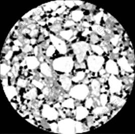
Fig.1 CT image of asphalt mixture
3 Material properties
In the model of asphalt mixture, the coarse aggregates retained on 2.36 mm sieve were counted in the sub-domain of aggregates. The fine aggregates passing through 2.36 mm sieve were filtered as sand
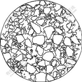
Fig.2 Boundary model of asphalt mixture
mastics. Elastic properties of aggregates were measured and applied to aggregates sub-domain, and plastic damage mastic properties were calibrated with direct tensile test (DTT).
Since the period of splitting test is relatively short, the main failure mechanism of asphalt mastic is tensile cracking. The viscous behavior of asphalt mastic can be ignored, therefore, the asphalt mastics were modeled as damaged plastic materials by LUBLINER et al [16]. The model assumes that the main failure mechanism of the mastic material is tensile cracking, and the uniaxial tensile response of mastic is characterized by damaged plasticity, as shown in Fig.3.

Fig.3 Response of asphalt mastic to tensile load [16]
Under direct tension the stress-strain response follows a linear elastic relationship until the value of the failure stress ��t0 is reached. The failure stress corresponds to the onset of micro-cracking in the asphalt mastic. Beyond the failure stress, the formation of micro-cracks is represented macroscopically with a softening stress-strain response, which induces strain localization in the asphalt mastic.
It is assumed that the uniaxial stress-strain curves can be converted into stress versus plastic strain curves. Thus,
![]() (1)
(1)
where ![]() is the equivalent plastic strain,
is the equivalent plastic strain, ![]() is the equivalent plastic strain rate, �� is the temperature, and fi (i=1, 2, 3, ��) is predefined field variable.
is the equivalent plastic strain rate, �� is the temperature, and fi (i=1, 2, 3, ��) is predefined field variable.
As shown in Fig.3, when the asphalt mastic is unloaded from any point on the strain softening branch of the stress-strain curves, the unloading response is weakened, that is, the elastic stiffness of the material appears to be damaged (or degraded). The degradation of the elastic stiffness is characterized by damage variable dt, which is assumed to be a function of plastic strain, temperature, and field variables:
![]() 0��dt��1 (2)
0��dt��1 (2)
The damage variable can take values from 0 (representing the undamaged material) to 1 (representing the total loss of strength).
If E0 is the initial (undamaged) elastic stiffness of the material, the stress-strain relation under uniaxial tension loading is
![]() (3)
(3)
The ��effective�� tensile stress is defined as
![]() (4)
(4)
The postfailure behavior of asphalt mastic for direct straining is modeled with tension stiffening. The tension stiffening is specified by applying a fracture energy cracking criterion. HILLERBORG et al [17] defined the energy required to open a unit area of crack as a material parameter by using brittle fracture concepts. Under tensile stress, the asphalt mastic will crack across some sections. This fracture energy cracking model can be invoked by specifying the postfailure stress as a tabular function of cracking displacement, ![]() as shown in Fig.4.
as shown in Fig.4.
The laboratory tests of elastic aggregate (rock) and plastic damage mastic were conducted to provide material input parameters for the FE models, as listed in Table 1. The aggregate modulus takes a typical value of 15 GPa for the limestone. The plastic damage mastic properties were calibrated by direct tensile test (DTT). The tensile failure stress is 1.26 MPa, and the postfailure stress-displacement curve of mastic is shown in Fig.4.
4 Micromechanical finite element simulation of asphalt mixture under splitting
The finite element software ABAQUS [18] was used to model the asphalt mixture microstructure. Fig.5 presents the geometry of the cross section of the asphalt concrete mixture specimen in ABAQUS, which was converted from the boundary model of digital images (Fig.2). As shown in Fig.5, the black parts are aggregates, the gray parts are asphalt mastics, and the white parts are air voids.
Table 1 Material parameters of aggregate and asphalt mastic
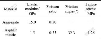
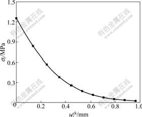
Fig.4 Postfailure stress-displacement curve of asphalt mastic used in this analysis
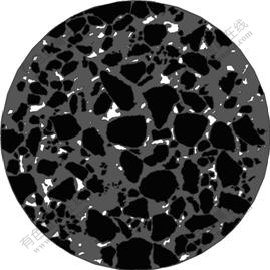
Fig.5 Geometry of asphalt mixture in ABAQUS
As mentioned previously, asphalt mixture are composed of very irregular aggregates, complex distributed mastics and air voids. The microstructures were divided into different aggregates, mastics and air voids subdomains. The finite element mesh was generated within the aggregates and mastics subdomains. The two- dimensional plane stress triangle elements (CPS3) were used, and the finite element mesh consisted of 65 568 elements, as shown in Fig.6.
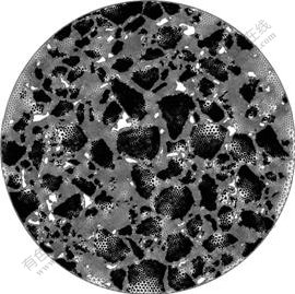
Fig.6 FEM meshes for asphalt mixture
After the microstructural finite element model has been developed, splitting test was simulated. A constant radial displacement rate was applied to numerical Marshall specimen. Both vertical and horizontal loadings were imposed (Fig.7) in order to compare the mechanics anisotropy of asphalt mixture.
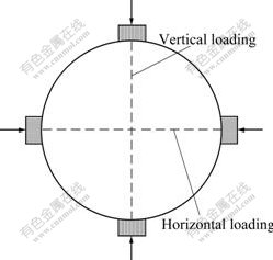
Fig.7 Directions of load applied in finite element
5 Results and discussion
5.1 Vertical loading results
The damage evolution approaches during vertical splitting load are indicated in Fig.8. The damage evolution variable is presented by tensile damage. Figs.8(a), (b), (c) and (d) represent the damage conditions when the vertical displacement reaches 0.5, 1.0, 2.0, and 3.0 mm, respectively. It can be easily found from Fig.8(a) that the initial damages occur in the asphalt mastics surrounding the coarse aggregates that are mainly located at three zones of the Marshall specimen:central, top, and down. As shown in Figs.8(b), (c) and (d), there are three main damage approaches near the middle vertical indirect tensile zone; the maximum damage factors occur at the edges of the two air voids near the center of the Marshall specimen; and the damage evolution approaches are mainly decided by the aggregate orientation and the distribution of air voids.
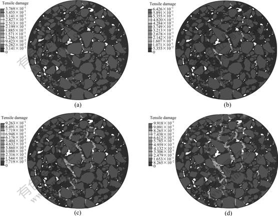
Fig.8 Damage evolution in Marshall specimen with different vertical displacements: (a) 0.5 mm; (b) 1.0 mm; (c) 2.0 mm; (d) 3.0 mm
Fig.9 indicates the maximum principal plastic strain in Marshall specimen when vertical displacement reaches 3.0 mm. Fig.10 shows the displacement magnitude contour in Marshall specimen in the same condition. It is found that the distributions of the principal strains and displacements are not radially symmetrical due to the effect of material heterogeneity. It is quite different from the conventional mechanics analysis results assuming that the asphalt mixture is uniform material.
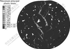
Fig.9 Maximum principal plastic strain contour in Marshall specimen when vertical displacement reaches 3.0 mm
5.2 Horizontal loading results
The damage evolution approaches during horizontal splitting load are indicated in Fig.11. Figs.11(a), (b), (c) and (d) represent the damage conditions when the horizontal displacement reaches 1.0, 2.0, 3.0, and 4.0 mm, respectively. It can be found from Fig.11(a) that the initial damages occurring in the asphalt mastics surrounding the coarse aggregates mainly locate at three zones of the Marshall specimen: central, left, and right. As shown in Fig.11s.(b), (c) and (d), there are two main damage approaches near the middle horizontal indirect tensile zone; the maximum damage factors occur at the edges of the air voids near the middle loading zone of the Marshall specimen; and the damage evolution approaches are mainly decided by the aggregate orientation and the distribution of air voids.
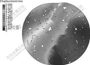
Fig.10 Displacement contour in Marshall specimen when vertical displacement reaches 3.0 mm
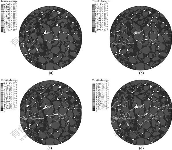
Fig.11 Damage evolution in Marshall specimen with different horizontal displacements: (a) 1.0 mm; (b) 2.0 mm; (c) 3.0 mm; (d) 4.0 mm
Fig.12 indicates the maximum distribution of principal plastic strains in Marshall specimen when horizontal displacement reaches 4.0 mm. Fig.13 shows the displacement magnitude contour in Marshall specimen under the same condition. It is found that the distributions of the principal strains and displacements are nearly radially symmetrical. It is different from the results of the vertical loading.
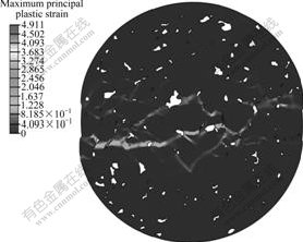
Fig.12 Maximum principal plastic strain contour in Marshall specimen when horizontal displacement reaches 4.0 mm
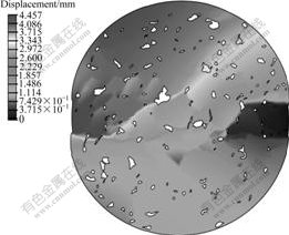
Fig.13 Displacement contour in Marshall specimen when horizontal displacement reaches 4.0 mm
6 Conclusions
(1) CT images combined with digital image processing techniques are effective methods to reveal microstructure of asphalt mixture with three phase compositions (aggregate, air void, and asphalt mastic).
(2) The damage evolution approach is significantly influenced by the material heterogeneity of asphalt mixtures, especially the aggregate orientation and the distribution of air voids.
(3) The results of vertical loading and horizontal loading of the same numerical specimen indicate that segregation and material heterogeneity of asphalt mixtures are the main reasons for the differences occurring during mechanics tests.
(4) The consideration of air void properties (air void content, air void shape and air void distribution) is essential when the micromechanical analyses of asphalt mixtures are conducted.
(5) The proposed method can be extended to the numerical analysis for the other micromechanical behaviors of asphalt concrete. However, more works are required to accurately describe different viscoelastic, viscoplastic, and even visco-elastic-plastic constitutive models.
References
[1] HASHIN Z. The elastic moduli of heterogeneous materials [J]. Journal of Applied Mechanics, 1962, 29: 143-192.
[2] HASHIN Z, SHTRIKMAN S. A variational approach to the theory of the elastic behaviour of multiphase materials [J]. Journal of the Mechanics and Physics of Solids, 1963, 11: 127-167.
[3] SOARES J B, COLARES F A, ALLEN D H. Considering material heterogeneity in crack modeling of asphaltic mixture [J]. Journal of the Transportation Research Board, 2003: 113-120.
[4] YOU Z, BUTTLAR W G. Discrete-element modeling to predict the modulus of asphalt concrete mixtures [J]. Journal of Materials in Civil Engineering, 2004, 16(2): 140-146.
[5] LIU Yu, DAI Qing-li, YOU Zhan-ping. Viscoelastic model for discrete element simulation of asphalt mixture [J]. Journal of Engineering Mechanics, 2009, 135(4): 324-333.
[6] ABBAS A, MASAD E, PAPAGIANNAKIS T, HARMAN T. Micromechanical modeling of the viscoelastic behavior of asphalt mixtures using the discrete-element method [J]. International Journal of Geomechanics, 2007, 7(2): 131-139.
[7] DAI Qing-li, YOU Zhan-ping. Prediction of creep stiffness of asphalt mixture with micromechanical finite-element and discrete-element models [J]. Journal of Engineering Mechanics, 2007, 133(2): 163-173.
[8] MASAD E, SOMADEVAN N. Microstructural finite-element analysis of influence of localized strain distribution on asphalt mix properties [J]. Journal of Engineering Mechanics, 2002, 128(2): 1105-1114.
[9] KOSE S, GULER M, BAHIA H U, MASAD E. Distribution of strains within hot-mix asphalt binders [J]. Journal of the Transportation Research Board, 2000: 21-27.
[10] PAPAGIANNAKIS A T, ABBAS A, MASAD E. Micromechanical analysis of viscoelastic properties of asphalt concretes [J]. Journal of the Transportation Research Board, 2002: 113-120.
[11] BIRGISSON B, SANGPETNGAM B, ROQUE R. Predicting viscoelastic response and crack growth in asphalt mixtures with the boundary element method [J]. Journal of the Transportation Research Board, 2002: 129-135.
[12] MASAD E, JANDHYALA V K, DASGUPTA N, SOMADEVAN N, SHASHIDHAR N. Characterization of air void distribution in asphalt mixes using X-ray computed tomography [J]. Journal of Materials in Civil Engineering, 2002, 14(2): 122-129.
[13] TASHMAN L, MASAD E, ANGELO J D, BUKOWSKI J, HARMAN T. X-ray tomography to characterize air void distribution in superpave gyratory compacted specimens [J]. International Journal of Pavement Engineering, 2002, 3(1): 19-28.
[14] WANG L B, PAUL H S, HARMAN T, ANGELO J D. Characterization of aggregates and asphalt concrete using X-ray computerized tomography: A state-of-the-art report [J]. Journal of the Association of Asphalt Paving Technologists, 2004, 73: 467-500.
[15] YU Jiang-miao, LI Xiao-jun, WANG Duan-yi, ZHANG Xiao-ning. Finite element modeling of asphalt mix with X-ray computerized tomograph processing [J]. Journal of Chang��an University: Natural Science Edition, 2006, 26(1): 16-19. (in Chinese).
[16] LUBLINERJ, OLIVER J, OLLER S, O?ATE E. A plastic-damage model for concrete [J]. International Journal of Solids and Structures, 1989, 25: 299-329.
[17] HILLERBORG A, MODEER M, PETERSSON P E. Analysis of crack formation and crack growth in concrete by means of fracture mechanics and finite elements [J]. Cement and Concrete Research, 1976, 6: 773-782.
[18] SORENSON H K. ABAQUS Theory and Users Manual Version 6.8 [M]. Rhode Island: Pawttucket, Inc., 2008.
Foundation item: Project(50808086) supported by the National Natural Science Foundation of China
Received date: 2009-08-24; Accepted date: 2010-01-18
Corresponding author: CHEN Ye-kai, PhD; Tel: +86-20-87111030-3004; E-mail: cheops@scut.edu.cn
(Edited by YANG Bing)
Abstract: A methodology was presented relating the microstructure of asphalt mixtures to their damage behavior. Digital image techniques were used to capture the asphalt mixture microstructure, and the finite element method was used to simulate the damage evolution of asphalt mixture through splitting test. Aggregates were modeled to be linearly elastic, and the mastics were modeled to be plastically damaged. The splitting test simulation results show that the material heterogeneity, the properties of aggregates and air voids have significant effects on the damage evolution approach. The damage behavior of asphalt mixture considering material heterogeneity is quite different from that of the conventional hypothesis of homogeneous material. The results indicate that the proposed method can be extended to the numerical analysis for the other micromechanical behaviors of asphalt concrete.
