
J. Cent. South Univ. (2012) 19: 537-546
DOI: 10.1007/s11771-012-1037-y![]()
Catenary action of restrained steel beam against progressive collapse of steel frameworks
LI Guo-qiang(���ǿ)1, 2, WANG Kai-qiang(����ǿ)3, 4, LIU Yu-shu(�����)1, CHEN Su-wen(������)1, 2
1. Department of Building Engineering, School of Civil Engineering, Tongji University, Shanghai 200092, China;
2. State Key Laboratory for Disaster Reduction in Civil Engineering, Tongji University, Shanghai 200092, China;
3. School of Civil Engineering, Wuhan University, Wuhan 430072, China;
4. China Construction 3rd Engineering Bureau Co. Ltd., Wuhan 430064, China
? Central South University Press and Springer-Verlag Berlin Heidelberg 2012
Abstract:
The changing law of internal forces during the whole deformation development process was analyzed. The process was divided into five stages based on the internal force state of the beam and the assumptions of internal force relationship of five stages were proposed. Then, the formulas for determining the midspan deflection of the steel beam under distributed load, which was restrained both in rotational and axial directions, were obtained using restraint coefficient method and rigid-plastic mechanism, thereby the deformation development process was expressed accurately in a quantified way. Priority was given to the analysis of the process from bending to tension-bending, then the final state totally depends on tension to resist the external loads, that is the problem of catenary action of the restrained beam under distributed load. Additionally, finite element analysis was carried out with software ABAQUS6.7 on a restrained steel beam under distributed load with different axial and rotational restraint coefficients. The accuracy of the formulas presented was verified by the results of the behavior of the restrained beams. Finally, error analysis was conducted and some formulas were corrected according to the reasons of errors. The calculated results of corrected formulas match the FEM analysis results better, thus the accuracy of these formulas is improved.
Key words:
1 Introduction
Steel beam under distributed load is mainly subjected to the combination effect of moment and shear force, and the axial force in steel beam is usually ignored. With the increase of the load, bending moments at midspan and ends of the steel beam increase accordingly, thus developing plastic hinges at these locations and large deflection at the beam midspan. In this case, the steel beam endures considerable axial force, which cannot be neglected when calculating the response of the beam. As the cross section yields fully, the axial force in the steel beam can further increase to resist the additional external loading, which results in the decrease of the bending moment at plastic hinge section because of the plastic interaction between axial force and bending moment. Finally, the steel beam mainly depends on the axial force to resist external loading and the steel beam breaks at midspan or ends. This process is commonly referred to as tensile catenary action.
A steel beam subjected to uniformly distributed load is illustrated in Fig. 1, where the beam is restrained on both ends. The response of half of the steel beam is shown in Fig. 2, accounting for symmetric restraints of the steel beam.
In Fig. 2, ![]() and
and ![]() (n=1, 2, 3) are end bending moment and midspan bending moment in stage n, respectively. Nn and qn (n=1, 2, 3) are axial force and distributed load in stage n, respectively.
(n=1, 2, 3) are end bending moment and midspan bending moment in stage n, respectively. Nn and qn (n=1, 2, 3) are axial force and distributed load in stage n, respectively.
Catenary action can increase the bearing capacity of a restrained steel beam [1-8]. But in this case, most steel beams reach plastic stage and develop large displacement. So, it is inappropriate to account as the benefit in conventional design. On the other hand, catenary action is very much influenced by axial rigidity, flexural rigidity and restrained rigidity, and it is hard to present a explicit model of catenary action, so experiment and numerical simulations are needed. For these reasons, catenary action is only considered in the condition of fire, blast and progressive collapse [9-15]. Concerns about catenary action of steel beam and composite beam under fire are mainly focused on the decrease of elastic modulus, increase of midspan deflection and variation of axial force and bending moment. As for blast and progressive collapse, besides extreme bearing capacity, the ductility and energy dissipation based on load- deflection response are more important. The studies of load-deflection response involve restrained stiffness, material nonlinearity, geometrical nonlinearity, etc. So, up to now, only IZZUDDIN [13] gave a simplified explicit model of axially restrained steel beam under distributed load, while the behavior of the steel beam under distributed load, which is restrained both in rotational and axial directions, is seldom studied yet. The research objective of this work is to give the distributed load and corresponding midspan deflection curve to serve as the basis of the further step of obtaining the energy dissipation capacity of steel beams.
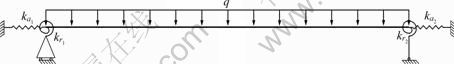
Fig. 1 Restrained beam under uniformly distributed load
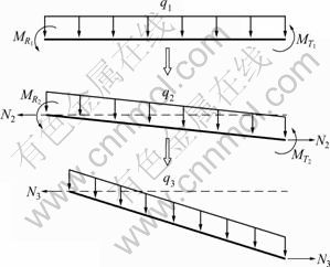
Fig. 2 Internal force and deformation of steel beam under distributed load
2 Analytical model and assumptions
2.1 Analytical model
The behavior of restrained steel beam under distributed load is shown in Fig. 3. Fig. 3(c) shows the horizontal displacement of support, which is in proportion to axial force within the steel beam.
The behavior of steel beam is divided into four stages:
1) Stage 1 is a elastic stage. The load deflection and midspan and end moment response are almost linear, determined by the flexural rigidity and restrained rigidity of the restrained steel beam. The axial force within steel beam is too small to be considered. The stage is ended with the formation of plastic hinge at the ends or midspan of the steel beam. The sequence of plastic hinges is determined by the magnitude of rotational restraint stiffness and flexural rigidity.
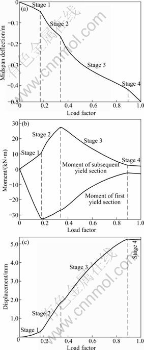
Fig. 3 Behavior of beam under distributed load: (a) Midspan deflection; (b) Midspan and end bending moments; (c) Horizontal displacement of support
2) After Stage 1, the section of plastic hinge develops plasticity over cross-sectional depth and the bending moment of the section reaches its maximum. Then, the axial force of the section increases to resist further distributed load with the decrease of bending moment, as illustrated in Fig. 3(b), and the section reaches plasticity first. But for the section reaching plasticity subsequently, as shown in Fig. 3(b), the axial force and bending moment increase simultaneously. When both sections yield through full sections, Stage 2 is over.
3) In Stage 3, the bending moments decrease and the axial forces increase for both end and midspan section, which leads to purely axial plastic hinge with plastic limit axial force and without bending moment.
4) For Stage 4, the axial force keeps constant. The steel beam develops midspan deflection to resist additional distributed load.
2.2 Assumptions
The scope of the proposed model and its underlying assumptions are as follows:
1) The steel beam with elastic/perfectly plastic material has I-shaped section;
2) Plastic hinges only happen at the end and midspan sections, and the plastic hinge follows rigid- plastic model;
3) The restraint of steel beam is symmetric and in elastic response.
4) According to Ref. [11], when the whole I-section yields, the axial force and moment correlation equation is given.
When neutral axis is in the web, then
![]() (1)
(1)
where Mp is the ultimate plastic moment of steel beam; Fp is the ultimate plastic axial force; M is the moment of steel beam; F is the axial force of steel beam; ��=Aw/(2Af), Aw is the web area of the section, and Af is the flange area of the section; �� is the ratio of flange thickness to web height. Since ��<<1, Eq. (1) can be rewritten as
![]() (2)
(2)
where t=(1+��)2/[��(2+��)].
When neutral axis is in the flange, then
![]() (3)
(3)
where r=Aw/(2Af+Aw). As shown in Fig. 4, the curves of Eqs. (2) and (3) intersect at point (1-tr2, r). For simplicity, the dashed curve from Eq. (2) can be replaced by the straight line:
![]() (4)
(4)
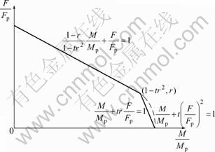
Fig. 4 Plastic interaction between axial force and bending moment
5) There are five stages in the analysis model: Stage 1 to Stage 4 and transition stage, as shown in Fig. 5. It is assumed that Stage 2 is taken to be linear and conforms to Eq. (4), and Stage 3 conforms to Eq. (3). This assumption will result in the uncontinuity between Stage 2 and Stage 3, thus transition stage is introduced here to make the whole curve continual. When the midspan deflection of the end of Stage 2 equals that of the beginning of Stage 3 or the distributed load of the beginning of Stage 3 is smaller than that of the end of Stage 2, a straight line is drawn between the point at the end of Stage 1 and the point at the beginning of Stage 3 as Stage 2. Otherwise, a straight line is drawn between the point at the end of Stage 2 and the point at the beginning of Stage 3 as transition stage.
6) Local bucklings are not considered in the analysis model.
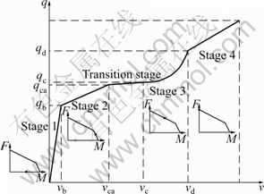
Fig. 5 Five stages of analysis model
3 Derivation of explicit formulation
Assuming that the axial restraint spring stiffness of both ends of the steel beam is equal to each other, then the equivalent axial stiffness of the steel beam kea is given as
 (5)
(5)
where kas is the axial restraint spring stiffness; ka is the axial stiffness of steel beam; ka=EA/l, E is the elastic modulus of steel, A is the sectional area of the steel beam, and l is the length of steel beam.
The equivalent rotational restraint stiffness of steel beam ker is given as
 (6)
(6)
where krs is the rotational restraint spring stiffness; kr is the rotational stiffness of steel beam; kr=EI/l, and I is the inertia moment of steel beam.
For convenience of derivation, rp is introduced here:
![]() (7)
(7)
During the derivation, MTn is the midspan moment of steel beam in stage n; MRn is the support moment of steel beam in stage n; vn is the midspan deflection of steel beam in stage n; qn is the distributed load of steel beam in stage n; Fn is the axial force of steel beam in stage n.
3.1 Stage 1
In the elastic stage, the midspan deflection vs and vf of beam under distributed loads, which is pinned and fixed at both ends, can be given as following formulas respectively
![]()
![]() (8)
(8)
When rotation restraint spring is considered, the restraint coefficients cf and cs are introduced as
![]()
![]() (9)
(9)
Then, the midspan deflection v1, midspan moment MT1 and end moment MR1 in Stage 1 can be expressed as
![]() (10)
(10)
![]()
![]() (11)
(11)
At the end of Stage 1, plastic hinges are formed at the midspan or ends of steel beam. From Eqs. (9)-(11), it is evident that the sequence of plastic hinges is decided by restraint coefficient cf.
When cf<0.75, plastic hinge is formed at midspan:
![]() (12a)
(12a)
When cf=0.75, plastic hinges are formed both at midspan and the end:
![]() (12b)
(12b)
When cf>0.75, plastic hinge is formed at the end:
![]() (12c)
(12c)
where MTb, MRb and qb are the midspan moment, end moment and distributed load at the end of Stage 1, respectively, and the corresponding midspan deflection vb can be written as
![]() (13)
(13)
It needs to be noted that the rotational restraint spring stiffness should be 6kr when cf equals 0.75.
3.2 Stage 2
In Stage 2, full plastic hinges are gradually formed at both the midspan and ends of steel beam, and the moment caused by axial force needs to be considered. In this work, the rigid-plastic mechanism is adopted. The whole elongation of the beam �� including the spring elongation can be written as the function of midspan deflection v2:
![]() (14)
(14)
The plastic deformations only occur at the plastic hinges of the midspan and ends of the steel beam, then the elastic elongation of the steel beam ��e is
![]() (15)
(15)
where ��Tp and ��Rp are the plastic elongations at the rigid-plastic hinges of the midspan and ends of the steel beam, respectively. The axial force in the beam F2 is only related to the elemental elastic elongation, so F2 can be given as
![]() (16)
(16)
The below equations can be obtained by Eq. (4) and plastic flow rule corresponding to internal forces yielding curves:
![]() (17)
(17)
![]() (18)
(18)
where ��Tp and ��Rp are the rotations for the plastic hinges of the midspan and ends of the steel beam, respectively; rp1=tr��rp
Since the rigid-plastic mechanism is utilized, the incremental plastic rotation is approximately taken as
![]()
![]() (19)
(19)
Substituting Eqs. (17), (18) and(19) into Eq. (16), we have
![]() (20)
(20)
From Eq. (20), we notice that only when v2>rp1, the axial force in the beam can be increased. For some few cases in which vb may be larger than rp1 when the ratio of span to depth is very big, the parameter v�� is introduced here:
![]() (21)
(21)
Integrating Eq. (20) from v��, the axial force for the beam in Stage 2, F2, is acquired as
![]() (22)
(22)
The midspan incremental deflection ��vca for the steel beam in Stage 2 can be given as follows according to the value of cf:
1) When cf��0.75, the midspan section of the steel beam will yield fully, and MT2 will be kept as Mp constantly; at this moment, the midspan incremental deflection ��vca1 can be calculated according to the cantilever beam problem as below. In addition, the midspan incremental deflection ��vca2 resulted from the rotation of support rotational spring should also be considered:
![]() 23)
23)
![]() (24)
(24)
where ��MRca is the end incremental moment for Stage 2; ��qca is the incremental distributed load for Stage 2.
So, the total midspan incremental deflection ��vca is given as
![]() (25)
(25)
Thereby, the midspan deflection vca and end moment MRca at the end of Stage 2 can be acquired as
![]()
![]() (26)
(26)
Axial force Fca in the beam at the end of Stage 2 can be obtained by substituting Eq. (26) into Eq. (22):
![]() (27)
(27)
The axial force and moment of end section at the end of Stage 2 conform to Eq. (4), that is
![]() (28)
(28)
We can have the following equations by substituting Eqs. (26) and (27) into Eq. (28) as
![]()
![]() (29)
(29)
��MRca can be solved by Eq. (29), then vca and Fca can be obtained by substituting ��MRca into Eqs. (25) and (27).
2) When cf>0.75, the end sections of the steel beam will yield fully, and MR2 will be kept as Mp constantly. The midspan incremental deflection ��vca can be calculated according to the pinned beam problems:
![]() (30)
(30)
where ��MTca is the midspan incremental moment for Stage 2.
From this, the distributed load qca and midspan deflection vca at the end of Stage 2 can be obtained as
![]() (31)
(31)
In this case, the axial force and moment of midspan section satisfy Eq. (4), and the midspan incremental moment of Stage 2 conforms to the equations below by taking the similar derivation as the case cf��0.75:
![]()
![]() (32)
(32)
��MTca can be solved by Eq. (32), then vca and Fca can be obtained by substituting ��MTca into Eqs. (25) and (27).
For the above-mentioned two cases, the midspan and end axial forces and moments are identical and all conform to Eq. (4):
![]() (33)
(33)
Establish the equilibrium equation of the beam ends as
![]() (34)
(34)
where qca is the distributed load at the end of Stage 2.
Substituting Eq. (33) into Eq. (34), we have
![]() (35)
(35)
When the midspan deflection at the beginning of Stage 3 obtained later is larger than that of the end of Stage 2, and the distributed load at the beginning of Stage 3 is larger than that of the end of Stage 2, the linear equation is established for the Stage 2:
![]() (36)
(36)
3.3 Stage 3
In Stage 3, both the end and midspan of the steel beam all yield fully, then the elastic elongation of the beam is given as
![]() (37)
(37)
The axial force and moment conform to Eq. (3) according to the assumptions. The following equations can be obtained by utilizing the plastic flow rule of internal forces yielding curves:
![]() (38)
(38)
![]() (39)
(39)
where y=(1-tr2)/(1-r); rp2=y��rp.
The incremental axial force can be given according to the analysis process of Stage 2 as
![]() (40)
(40)
From Eq. (40), it is noticed that only when v3>2rp2, the axial force in the beam can be increased, so the maximum of vca and 2rp2 is taken as the beginning point of midspan deflection for Stage 3, namely vc=max(vca, 2rp2). Integrating Eq. (40) from vc, the incremental axial force in the beam for Stage 3 is acquired as
![]() (41)
(41)
Then, the axial force in the beam F3 is
![]() (42)
(42)
where Fc is the axial force in the beam at the beginning of Stage 3.
When a transition stage is introduced here, we assume that the axial forces and moments at fully yielding sections still conform to Eq. (4), so we can get
![]() (43)
(43)
When no transition stage exists, Fc is equal to the axial force in the beam at the end of Stage 2, namely Fc=Fca.
In Stage 3, the end and midspan axial forces and moments conform to Eq. (3):
![]() (44)
(44)
Establish the equilibrium equation of the beam ends as
![]() (45)
(45)
By substituting Eqs. (41) and (44) into Eq. (45), we can have
![]()
![]() (46)
(46)
Since the end plastic hinges are rigid hinges, before the formation of plastic hinges, all the rotations are brought by the rotational springs. When the sections yield fully, the axial forces increase continually, while the section moments and rotational spring moments keep decreasing (these two variables keep the same all the time). The decrease of the rotational spring moments will result in the rotation diversion from the end rotational springs to yielding sections, which will further bring about the plastic elongation according to the plastic flow rule. This should be considered when calculating ��F3. Assuming the actual elongation corresponding to midspan deflection increment as ��F3r, then the corresponding moment increment ��M3r and rotation diversion ����3r can be obtained from Eq. (3) as
![]() (47)
(47)
The plastic elongation ��3rp corresponding to all the increments mentioned above is given as
![]() (48)
(48)
And the corresponding decrease of axial force ��F3rp is given as
![]() (49)
(49)
where ![]()
The summation of actual increment of axial force ��F3r and the decrease of axial force caused by the plastic elongation should be equal to ��F3 obtained from Eq. (41), that is:
![]() (50)
(50)
By using the revised ��F3r to substitute ��F3, we have
![]()
![]() (51)
(51)
The plastic ultimate axial force at the end of Stage 3 is given as
![]() (52)
(52)
where Fd is the axial force at the end of Stage 3, ��Fd is the incremental axial force for Stage 3. We can get from Eqs. (41) and (50) that
![]() (53)
(53)
where vd is the midspan deflection of the beam at the end of Stage 3. By solving Eq. (53), we can obtain vd as
![]() (54)
(54)
And the distributed load qd at the end of Stage 3 can be obtained by substituting vd into Eq. (51) as
![]()
![]() (55)
(55)
When no transition stage is needed, to ensure the curve continuity between Stage 2 and Stage 3, the distributed load qc at the end of Stage 2 is obtained by substituting vc into Eq. (51) as
![]() (56)
(56)
Then, establish the linear equation of Stage 2 as
![]() (57)
(57)
3.4 Stage 4
In Stage 4, the sectional moment of plastic hinge is close to 0, so there is only axial force in steel beam to resist the loads. The equilibrium equation is expressed as
![]() (58)
(58)
3.5 Transition stage
When transition stage is needed, the linear equation is expressed as
![]() (59)
(59)
where vca and qca are the midspan deflection and distributed load at the end of Stage 2, respectively; vc and qc are the midspan deflection and distributed load at the beginning of Stage 3, respectively.
The equations of midspan deflection and distributed load of each stage of the restrained steel beam under uniformly distributed load are derived. When the restrained steel beam is subjected to concentrated load in some case, it can be transformed into distributed load and the equations are also applicable.
4 Formulas with too small rotational stiffness
When the rotational stiffness is too small, the behavior of steel beam is similar to that of a simply supported steel beam with axial restraint, as shown in Fig. 6. It can be calculated using the equations of simply supported steel beam with axial restraint proposed in Ref. [5].
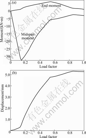
Fig. 6 Response of steel beam with too small rotational stiffness: (a) End and midspan moments; (b) Horizontal displacement of support
5 Numerical example
To validate the formulas proposed in this work, static elasto-plastic analysis is carried out using finite element software ABAQUS6.7 [16] to acquire the distributed load-midspan deflection curve of steel beam. The large deformation effect is considered in the FEM analysis. In addition, to improve the precision, quadric Timoshenko beam element B22 is adopted to consider the lateral shear deformation [3]. Steel is perfect elasto-plastic material; the elastic modulus is taken as 206 GPa, yield strength is taken as 235 MPa and Poisson ratio is taken as 0.3; the I-section is 300��150��10��12 (H��B��tb��tf, mm). Here, axial restraint coefficient pa stands for the ratio of axially restrained stiffness to the axial stiffness of steel beam, and rotational restraint coefficient pr stands for the ratio of rotationally restrained stiffness to the rotational stiffness of steel beam. pa takes the values of 0.5, 1.0 and 10.0, while pr takes the value of 0.1, 0.5, 1.0 and 10.0. The result comparisons of FEM analysis and proposed formulas are shown in Figs. 7-9.
It can be observed from Figs. 7-9 that the results from FEM analysis and the proposed equations agree well with each other. The proposed formulas can meet the accuracy requirement of projects and can be used in the calculation of structures under blast loading and the component energy dissipation during progressive collapse. It is also illustrated that there is some deviations between the results of FEM analysis and the proposed formulas in the intersection of Stage 2 and Stage 3. The closer the restrained stiffness to the self stiffness of steel beam is, the better the results of the proposed formulas match the FEM analysis results. When the restrained stiffness is too large or too small, there will be very large concentrated plastic deformation, which will increase the deviation between the assumptions and realistic situations, so the results from the proposed formulas will deviate from the FEM analysis results and the convergence capability will also become worse.
6 Error analysis and formula correction
6.1 Error analysis
As we know, there is still some deviations between the results of FEM analysis and the proposed formulas. The main reasons can be listed as below:
1) Because of the rigid-plastic mechanism, when the midspan section yields fully in Stage 2, the midspan deflection caused by rotation of support springs is only the function of rotation of the springs and the length of the component. However, in real situation, the deformation of steel beam changes from straight line to curve line with the gradual extension of yielding area at the midspan, and the midspan deflection increment ��vca2 also decreases accordingly.
2) With the increase of external load, the horizontal displacement of support also increases gradually and the end moment caused by distributed load decreases gradually, which is not considered in this work.
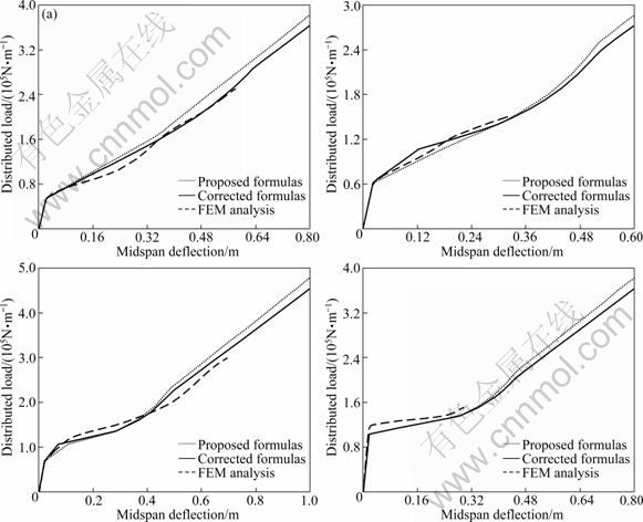
Fig. 7 Distributed load and midspan deflection of proposed model: (a) pa=0.5, pr=0.1; (b) pa=0.5, pr=0.5; (c) pa=0.5, pr=1.0; (d) pa= 0.5, pr=10.0
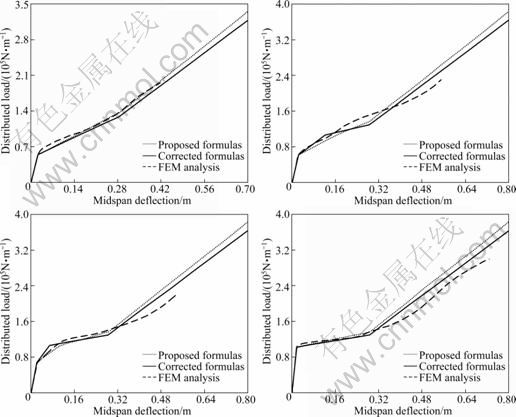
Fig. 8 Distributed load and midspan deflection of proposed model: (a) pa=1.0, pr=0.1; (b) pa=1.0, pr=0.5; (c) pa=1.0, pr=1.0; (d) pa= 1.0, pr=10
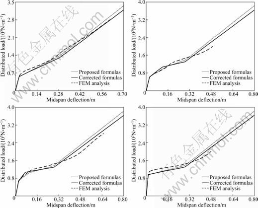
Fig. 9 Distributed load and midspan deflection of proposed model: (a) pa=10.0, pr=0.1; (b) pa=10.0, pr=0.5; (c) pa=10.0, pr=1.0; (d) pa=10.0, pr=10
6.2 Formula correction
According to the first error reason, ��vca2 is taken as half of its original value:
![]() (60)
(60)
According to the second error reason, a correction factor of 0.95 is introduced in Stage 4, so we have
![]() (61)
(61)
In the meantime, to ensure the continuity of Stage 3 and Stage 4, the revised equation of q3 is given as
![]()
![]() (62)
(62)
The results after correction are also shown in Figs. 7-9. It can be found that the results of the corrected formulas are closer to the results of FEM analysis and more accurate. However, even after correction, the results in Stage 4 are still larger than the results of FEM analysis, and a larger correction factor is suggested to ensure the safer results.
7 Conclusions
1) The changing law of internal forces during the whole deformation development process of steel beams is analyzed. The process is divided into five stages based on the internal force state of the beam and the model for analyzing the behavior of restrained steel beam is proposed.
2) It is applicable and effective to use the restraint coefficient method and rigid-plastic mechanism to derive the formulas for determining the midspan deflection of the restrained steel beam with catenary action.
3) These proposed formulas are validated against finite element analysis carried out with software ABAQUS6.7 on a restrained steel beam under distributed load with different axial and rotational restraint coefficients. There is good agreement between the results of the behavior of the restrained beams obtained by the formulas and FEM analysis.
4) Error analysis is made to investigate the reasons for the deviation between the results of FEM analysis and the proposed formulas, and some formulas are corrected accordingly. The results of the corrected formulas have a better agreement with the results of FEM analysis.
5) The proposed method is able to calculate the deformation and energy dissipation of restrained steel beams, thus offering a practical tool for the progressive collapse analysis of structures under extreme loading.
References
[1] ELLINGWOOD B, LEYENDECKER E. Approaches for design against progressive collapse [J]. Journal of the Structural Division, 1978, 104(3): 413-423.
[2] FERAHIAN R H. Buildings: Design for prevention of progressive collapse [M]. Ottawa: Civil Engineering-ASCE, 1972: 66-69.
[3] Department of Defence. Design of Buildings to Resist Progressive Collapse UFC 4-023-03 [S].
[4] HAMBURGER R, WHITTAKER A. Design of steel structures for blast-related progressive collapse resistance [J]. Modern Steel Construction, 2004(3): 45-51.
[5] CORLEY W G, SMITH R G, COLARUSSO L J. Structural integrity and the oklahoma city bombing [J]. Concrete Construction, 2001, 46(12): 29-30.
[6] Ingvar Schousboe. Bailey��s crossroads collapse reviewed [J]. Journal of the Construction Division, 1976, 102(2): 365-378.
[7] KIM Jin-koo, PARK Jun-hee. Design of steel moment frames considering progressive collapse [J]. Steel and Composite Structures, 2008, 8(1): 85-98.
[8] ZHOU Q, YU T X. Use of high-efficiency energy absorbing device to arrest progressive collapse of tall building [J]. ASCE Journal of Engineering Mechanics, 2004, 130(10): 1177-1187.
[9] GUO Shi-xiong. The behavior of restrained steel beam during heating and cooling and the damage of beam-to-column connection [D]. Shanghai: Tongji University, 2006: 52-80. (in Chinese)
[10] WANG Yin-zhi. Behavior and design of composite beam in fire with considering global structure effect [D]. Shanghai: Tongji University, 2006: 107-153. (in Chinese)
[11] YIN Ying-zhi, WANG Yong-chang. Analysis of catenary action in steel beams using a simplified hand calculation method: Part 1. Theory and validation for uniform temperature distribution [J]. Journal of Constructional Steel Research, 2005, 61(2): 183-211.
[12] YIN Ying-zhi, WANG Yong-chang. Analysis of catenary action in steel beams using a simplified hand calculation method: Part 2. Validation for non-uniform temperature distribution [J]. Journal of Constructional Steel Research, 2005, 61(2): 213-234.
[13] IZZUDDIN B A. A simplified model for axially restrained beams subject to extreme loading [J]. Steel Structures, 2005, 5(5): 421-429.
[14] IZZUDDIN B A, VLASSIS A G, ELAHAZOULI A Y, NETHERCOT D A. Progressive collapse of multi-storey buildings due to sudden column loss: Part I. Simplified assessment framework [J]. Engineering Structures, 2008, 30(5): 1308-1318.
[15] VLASSIS A G, IZZUDDIN B A, ELAHAZOULI A Y, NETHERCOT D A. Progressive collapse of multi-storey buildings due to sudden column loss: Part II. Application [J]. Engineering Structures, 2008, 30(5): 1424-1438.
[16] SHI Yi-ping, ZHOU Yu-rong. Examples for ABAQUS finite element analysis [M]. Beijing: China Machine Press, 2006: 165-207. (in Chinese)
(Edited by HE Yun-bin)
Foundation item: Project(2006BAJ01B02) supported by the National Science and Technology Pillar Program during the Eleventh Five-Year Plan Period of China
Received date: 2011-02-23; Accepted date: 2011-05-27
Corresponding author: LIU Yu-shu, PhD; Tel: +86-21-65980251; E-mail: ysliu@tongji.edu.cn
Abstract: The changing law of internal forces during the whole deformation development process was analyzed. The process was divided into five stages based on the internal force state of the beam and the assumptions of internal force relationship of five stages were proposed. Then, the formulas for determining the midspan deflection of the steel beam under distributed load, which was restrained both in rotational and axial directions, were obtained using restraint coefficient method and rigid-plastic mechanism, thereby the deformation development process was expressed accurately in a quantified way. Priority was given to the analysis of the process from bending to tension-bending, then the final state totally depends on tension to resist the external loads, that is the problem of catenary action of the restrained beam under distributed load. Additionally, finite element analysis was carried out with software ABAQUS6.7 on a restrained steel beam under distributed load with different axial and rotational restraint coefficients. The accuracy of the formulas presented was verified by the results of the behavior of the restrained beams. Finally, error analysis was conducted and some formulas were corrected according to the reasons of errors. The calculated results of corrected formulas match the FEM analysis results better, thus the accuracy of these formulas is improved.
