
Trans. Nonferrous Met. Soc. China 22(2012) s222-s231
Prediction of texture evolution under varying deformation states through crystal plasticity finite element method
LI Hong-wei, YANG He
State Key Laboratory of Solidification Processing, Northwestern Polytechnical University, Xi��an 710072, China
Received 28 August 2012; accepted 25 October 2012
Abstract:
An explicit model controlled by a linear equations set was developed. This model was directly solved by the complete pivot GAUSSIAN elimination method without any iteration. In addition, crystallographic-system based solving procedure was proposed to reduce the additional calculation caused by grain rotation. By establishing crystal plasticity finite element model (CPFEM), the model was verified by comparing the predicted texture to the experimental results. Then, the model was applied to predict textures under different deformation states achieved by adjusting the ratio (k) of the loading velocities in Z and Y directions. The results show that the model is reliable in texture prediction (good agreement with the experiments in compression, tension, simple shear and plane-strain compression) and much more efficient (more than 100 times) than the implicit model; with the increasing of k, the strong texture progresses from ��35�� to normal direction to fiber texture in the {111} plane and enhances in intensity; the texture intensity drops dramatically when the strain rate increases from 0.1 s-1 to 100 s-1, while drops slowly when the strain rate increases from 100 s-1 to 7��104 s-1, which indicates the computational stability of the model for simulation of ultra-high strain rate deformation.
Key words:
crystal plasticity; texture evolution; deformation state; strain rate; explicit model;
1 Introduction
Texture evolution takes place during plastic deformation of metals, which in turn results in anisotropic mechanical properties of the deformed part [1]. Additionally, texture evolution varies with different deformation states sensitively. So, texture prediction is an effective way for deformation design and performance control. Crystal plasticity model is widely known and utilized for texture prediction in metal deformation process. However, the major drawback of crystal plasticity models lies in computational issue [2], i.e. inefficient and unstable solution. The widely used Newton-Raphson (N-R) iteration approach [3-5] is computationally stable and accurate but inefficient due to massive iterations existing both at the local level to update the stress and globally to enforce equilibrium [6]. As to the implicit algorithms, rate-tangent method [7] and Euler forward method [8] are typical representatives of explicit algorithms, which promote the computational efficiency remarkably [6]. However, they were very rigid needing very small step length [8].
On the other hand, grains aggregate should be taken into account for prediction of texture evolution. Grains interaction during deformation process is a challenging issue in crystal plasticity modeling. To the problem of no grain interaction considered in the Taylor model [9], van HOUTTE et al [10] proposed a bicrystal model, so called LAMEL model, which calculated two crystals at the same time so that to consider grain interactions. The model was improved by van HOUTTE et al [11] from LAMEL model to ALAMEL model by considering two neighboring domains, the subdivision of a grain. Subsequently, MAHESH [12] proposed a binary-tree based model to maintain traction continuity across grain interface within an aggregate by dividing the aggregate to subaggregates and then subdividing until the smallest sub-divisions contain only single grains. Similarly, KUMAR et al [13] proposed a ��stack�� model based on the ALAMEL model to account for intra interactions by means of an arbitrary number N of co-deforming domains. In addition, self-consistent models [14-16] consider grain interaction by allowing constraints on shearing directions of a grain but not applying full constraints. Also, crystal plasticity finite element model (CPFEM) [17] considers grain interactions by the nature that the nodes in finite element model are constrained by each other.
In this work, Taylor series expansion was applied to recast the high-order nonlinear equation accounting for rate dependent shear strain rate into a linear equations set. Then, an incremental explicit model was deduced with the linear equations set as the control equation. This model was solved directly by the complete pivot Gaussian elimination method, which avoids iterations in the implicit model and overcomes the shortcomings caused by the approximation adopted in aforementioned explicit models. By developing user subroutine VUMAT, this model was embedded in the commercial software ABAQUS/Explicit. The model was verified on texture prediction in axial compression, tension, simple shear and plane-strain compression through a CPFEM. Then, the model was applied to investigate texture evolution under varying deformation states and strain rates.
2 Crystal plasticity finite element modeling
2.1 Constitutive relation
The elastic constitutive relation for the stress in each grain is taken as
 (1)
(1)
where  is an elastic strain measure, R is a fourth-order elasticity tensor, I is the second-order identity tensor. T* has the relation with T as:
 (2)
(2)
where is the non-plastic deformation gradient with the plastic deformation gradient Fp evolving as
  .
.
The plastic part of velocity gradient can be calculated through the crystal plasticity theory as
 (3)
(3)
where  and
and  are time-independent orthonormal unit vectors which define the slip direction and slip plane normal of the ��-th slip system in a fixed reference configuration, and
  is the Schmid tensor.
2.2 Flow rule
The rate-dependent flow rule is adopted. The plastic shearing rate on the ��-th slip system can be given by an exponential type law in terms of the resolved shear stress (RSS)  and deformation resistance of the ��-th slip system
  as
as
 (4)
(4)
where  is a reference value, m is the strain rate sensitive coefficient of material, and the symbol sign stands for getting the sign symbol of .
In Eq. (4), RSS may be approximated by
 (5)
(5)
2.3 Work hardening
The KOCKS-type hardening rule is adopted. evolves as
 (6)
(6)
where  is the rate of strain hardening on slip system �� due to shearing on the slip system ��, which is related to a single slip hardening rate,
  , and the hardening matrix,
  , as
, as  (no sum on �� here ) with
  . Parameters h0, ss and a are hardening parameters. The hardening matrix, , given by ZHOU et al [18] is adopted to account for the latent hardening and self-hardening of a crystal.
2.4 Numerical algorithm
As described above, rate dependent crystal plasticity model contains implicit equations with respect to  and
and Moreover, Eq. (5) indicates high-level nonlinearity of this model since m is usually very small for metals (0.01-0.05). These characters bring trouble for numerical solution in computational efficiency and stability. Therefore, many research works have been done on numerical algorithms as discussed in Section 1. Here, we focus on the work presented by KALIDINDI et al [3]. In Ref. [3], a fully implicit time-integration procedure was presented and relative equations were deduced. Also, a two-level N-R iterative method was adopted for numerical solution. It was found that it was hard to find a suitable initial value for convergence of the N-R iteration in each time step in finite element calculation even though a very small step length was adopted [4]. So, we introduced a homotopy auto-changing continuation method to iterate a suitable initial value before the N-R iteration algorithm was invoked. Although this method achieved the computational stability, it is low efficient due to much iteration additionally introduced by the homotopy continuation method besides the N-R method. As a result, it was applied only in calculations with a single crystal.
Here, a novel explicit model was established based on Ref. [3]. During the modeling, t and �� = t + ��t denote the time at the start and the end of each increment, respectively. Taylor series expansion of Eq. (5), neglecting the high-order terms, is expressed as
 (7)
(7)

When  is assumed,
  can be simplified since is unchangeable with deformation when calculations are carried out in the crystallographic system, which will be discussed in Section 2.6.
So, the increments of stress and resistance of slip systems can be deduced based on the algorithm proposed by KALINDINDI et al [3]. They take the forms as

 (8)
(8)
 (9)
(9)
where
 (10)
(10)
Since all variables at time t are known, Eqs. (8) and (9) are the equations set with the unknowns of  and
and  For the purpose of efficiency, a two-level procedure is adopted here. Firstly,
  is fixed at its value at time t, Eq. (8) can be deduced and written in its components as
 (11)
(11)
where


Since both  and
and  can be calculated directly, Eq. (11) is a linear equations set with the unknowns of
  . Here, the complete pivot Gaussian elimination method is adopted for the solution. After getting , the second-level solving procedure starts. Equation (9) can also be rewritten into a linear equations set in the same way, expressed as
 (12)
(12)
where


So,  can also be updated with the new by the complete pivot GAUSSIAN elimination method. Then, a recalculation loop is invoked for a new by the new until the following equations are satisfied.
 (13)
(13)
 (14)
(14)
Here, s0 is the initial deformation resistance of slip systems, and all slip systems are assumed to have the same value.
2.5 Texture tracking
Texture evolution is tracked through a rotation matrix Q, which is formed through three Euler angles in Kalidindi��s notation (see Ref. [3]). This matrix was defined to quantify the relation of vectors or tensors between the crystallographic system (Cc) and the global system (Cg). Taking advantage of this rotation matrix, there exist:
 (15)
(15)
 (16)
(16)
where Dg stands for a tensor in Cg and Dc stands for the one in Cc.
In order to track texture evolution, the matrix Q should be stored and updated step by step during forming process. The equation proposed by KALIDINDI et al [3] is employed as
 (17)
(17)
where  is the non-plastic part of the deformation gradient at time ��.
2.6 Stress update systems
Since vectors and tensors related to crystals are stored in Cc, such as and R, while the ones related to deformation, such as F, E, T and Q, provided by the finite element method are stored in Cg. As we all know, all tensors and vectors must be in the same system during constitutive update. Therefore, the transformation between systems for vectors and tensors is needed. There are two ways for the transformation. One is to transfer the ones in Cc to Cg so as to perform constitutive update in Cg, and the other is to transfer the ones in Cg to Cc so as to perform constitutive update in Cc. However, the first way is expensive since the sizes of internal variables related to crystals increase with the increase of the number of elements (ne) and crystals (nc) at the level of n e��nc. Nevertheless, the variables need to be transferred in the second way are only related to elements. Thus, all variables in Cg are transferred to Cc in this work in order for computational efficiency. In this case, tensors related to crystals are time-independent constants for all crystals so that there is much less calculation to do. Here, we have to mention that the obtained stress T and orientation update matrix F* are also in Cc. Therefore, it is required to transfer them to Cg to return to finite element method and to calculate texture update.
2.7 Numerical procedure
According to the presented model, a user subroutine VUMAT was developed under the environment of ABAQUS/Explicit [19]. The procedure for coding is listed below.
1) Get known variables of F(t) and F(��) in Cg;
2) Grain number (k) starts from 1;
3) Get variables of  ,
,  ,
,  ,
,  and
and  (�� starts from 1);
4) Transfer F(t) and F(��) to Cc;
5) Calculate A,  ,
,  and
and  ;
;
6) Calculate Kijkl and Hkl with  ;
;
7) Solve Eq. (11) to get  ;
;
8) Calculate  and
and  with the newly obtained ;
9) Solve Eq. (12) to get a new  ;
;
10) If Eqs. (13) and (14) are satisfied, go on; if not, return to Step 6 with the new ;
11) Transfer  and
and  to Cg;
12) Update  via Eq. (3),
 ,
,  ,
,  ,
,  and
and  ;
;
13) Update  by Eq. (16);
14) If k>N (total grains), go on, otherwise, k=k+1, return to Step 3;
15) Calculate the volume-average Cauchy stress on the material point  ;
;
16) Carry out the calculations of  (with
(with  ) to meet the requirements on stress and strain in ABAQUS/Explicit ;
17) Subroutine ends and returns.
2.8 Finite element modeling
A finite element model is created as shown in Fig. 1. There are 1000 C3D8R (an eight-node linear brick reduced integration and hourglass control element in ABAQUS/Explicit) elements within a 1 mm��1 mm��1 mm cube. The primary load is along the V2 direction and the second one is along the V3 direction. The bottom face of the cube is fixed in the Y-direction. The left and right lateral sides are with constraints which keep the surface in a plane during deformation. Thus, the effects of other neighboring materials can be simulated.
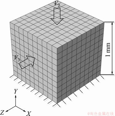
Fig. 1 Finite element meshes and loading configuration
About 1000 orientations representing the initial texture are mapped on the 1000 elements one by one. Therefore, one element stands for an individual grain and grain interactions can be taken into account from the equilibrium between neighboring elements.
3 Model verification
3.1 Initial conditions
The initial texture represented by 1000 random distributed orientations is shown in Fig. 2. Four typical forming processes are introduced to verify the model in texture prediction. They are uniaxial compression, uniaxial tension, simple shear and plane-strain compression which has the essence as sheet rolling process. The deformation in all of the processes reaches a true strain of 1.4 with the strain rate of 1 s-1. The material used in simulation is oxygen free high conductivity (OFHC) copper, whose parameters are listed in Table 1. 12 slip systems are considered in the simulations.
3.2 Model efficiency
Uniaxial compression is calculated to study the efficiency of the model. In the simulation, the machine is a workstation with the configurations of 8 Intel Xeon CPUs @ 2.53 GHz, and 12.0 GB memory. CPU time by using the presented algorithm (only 1 CPU used in this case) was compared with that by using the implicit algorithm proposed in Ref. [4], as listed in Table 2. In this table, N e is element number, Nc is crystal number within one element, t-ex is the CPU time costed by the explicit model, t-im is the one costed by the implicit model, and ��tmax and ��tmin are the maximal and minimal time increments, respectively. The presented algorithm shows much more efficient than the implicit algorithm (more than 100 times).
3.3 Texture evolution in uniaxial compression
Uniaxial compression is achieved by releasing the constraint of V3 in Fig. 1. The pole figures of {100}, {110} and {111} at a true strain of 1.4 are presented in Figs. 3(a), (b) and (c), respectively. The experiments carried out by BRONKHORST et al [20] are taken for comparison. Figure 3 shows that both the predictions and experiments capture the {110} fiber texture and {111} plane texture well. Moreover, they have the quantitatively comparability.
Table 1 Material constants of OFHC copper
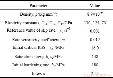
Table 2 Comparable analysis of computational efficiency
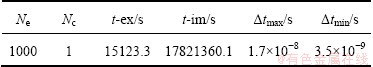
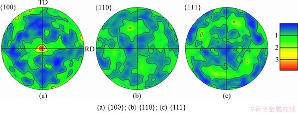
Fig. 2 Initial texture represented by 1000 randomly distributed orientation
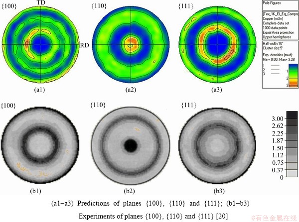
Fig. 3 Textures in axial compression at true strain of 1.4
3.4 Texture evolution in uniaxial tension
By releasing V 3 and reversing V2 in the model in Fig. 1, uniaxial tension is calculated for texture evolution. Figure 4 shows that both the prediction and experiment results capture the {111} fiber texture well.
3.5 Texture evolution in simple shear
By releasing V3 and rotating V2 by 90�� in the model in Fig. 1, simple shear is calculated for texture evolution. Figure 5 shows that the predictions agree with the experiments well. The highest-intensity textures occur at 30��, 90��, 150��, 210��, 270��, 330�� ^ND on the {111} plane, respectively.
3.6 Texture evolution in plane-strain compression
Setting V3=0, i.e. keeping the XY-plane fixed, the plane-strain compression is achieved. The typical textures in plane-strain compression are predicted, as shown in Fig. 6, which agree with the experiments. The highest intensity texture appears at ��35�� to ND along RD on the {111} plane.
From Sections 3.3 to 3.6, it can be found that the presented model captures all of the important textures in the deformation processes including uniaxial compression, uniaxial tension, simple shear and plane-strain compression. Therefore, the model is reliable to be applied for prediction of texture evolution with varying deformation conditions.
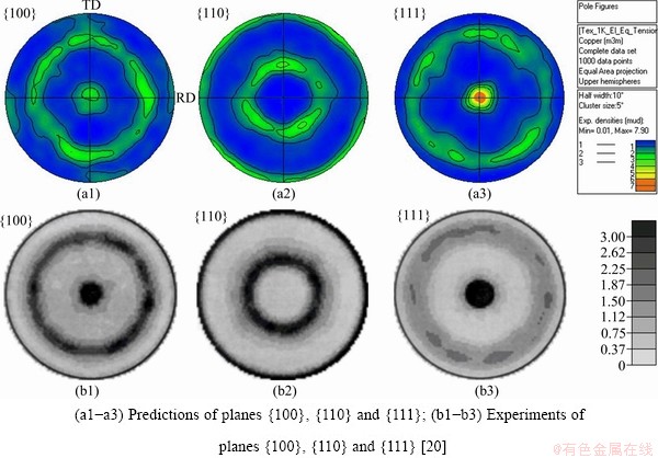
Fig. 4 Textures in axial tension at true strain of 1.4
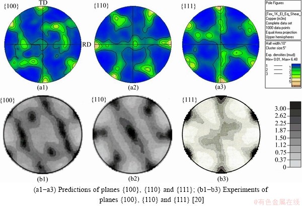
Fig. 5 Textures in simple shear at true strain of 1.4
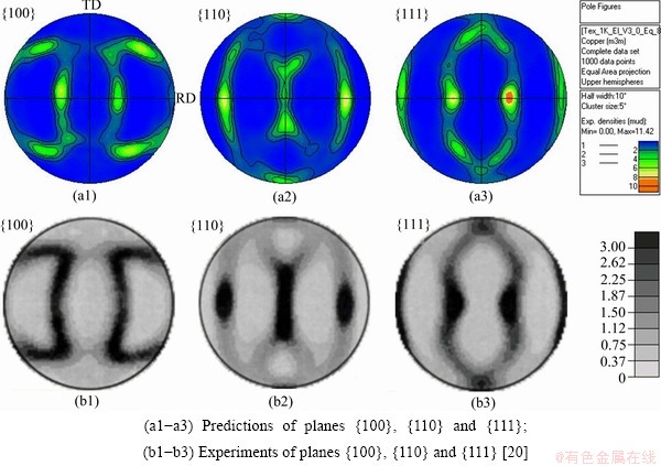
Fig. 6 Textures in plane-strain compression at true strain of 1.4
4 Texture evolution with varying deformation conditions
The model was applied to investigate the texture evolution under different conditions. The effects of deformation states, strain rates, and slip systems are studied.
4.1 Effects of deformation states
Different deformation states are achieved by adjusting the ratios of V3 to V2, i.e. k=V3/V 2. If there is no constraint on V3, the deformation is the uniaxial compression. In this process, V3 is passive and the texture evolution is illustrated in Fig. 3. When a weak constraint is applied on V3, e.g. k=-0.43 (V2 is negative), the {111} plane texture in Fig. 3 rotates to ��35�� to ND along RD, as shown in Fig. 7(a), while the {100} texture maintains the characteristics of that in uniaxial compression. With increasing constraint on V3 until the plane-strain compression (k=0) is achieved, texture characteristics in uniaxial compression disappear completely (as shown in Fig. 6). When the constraint on V3 enhances further, e.g. k=0.14, k=0.43 and k=0.71 (both V2 and V3 are negative), the strong textures progress from ��35�� to ND in plane-strain compression to fiber texture along RD direction on the {111} plane, as shown in Figs. 7(b)-(d). It shows varying deformation states change grain orientations and thus textures remarkably. Additionally, the texture intensity shows an increasing tendency with the increase of k.
4.2 Effects of strain rates
Moreover, the strain rate of deformation does affect on texture evolution. As our study, the texture types and the positions of strong texture do not change with strain rate. However, the intensity of texture reduces with the increase of strain rate, as shown in Fig. 8. It can be found that the texture intensity drops dramatically when the strain rate increases from 10-1 s-1 to 102 s-1, while the reduction slows down when the strain rate increases from 102 s-1 to 7��104 s-1. It can be explained that the large strain rate makes no enough time for grain orientation rotation in the first range. Then, in the second range, the strain rate has already reached a high level, i.e., there has not been enough time for grain orientation rotation.
4.3 Effects of slip systems
Generally, only 12 slip systems participate the deformation of a face-centered cubic (FCC) metal. However, the experimental observation finds that  slip systems are activated in deformation of FCC metals. So, here, different slip systems are considered to study their effects on textures. Figure 9 shows much more relaxed textures in terms of orientations distribution and texture intensity in case of 12+6 slip systems. It is because more slip systems participating deformation improve the deformation anisotropy of a grain; more homogeneous deformation cause less orientations rotating to the referred orientation.
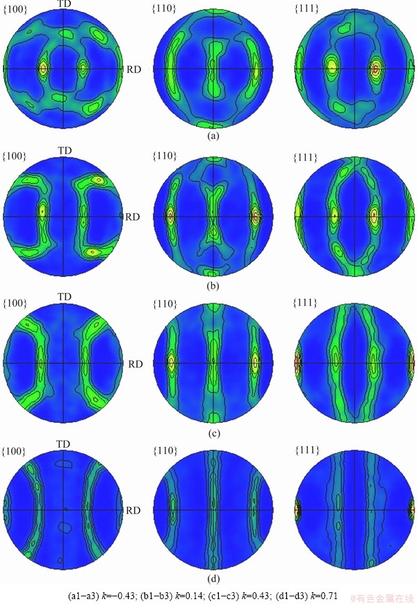
Fig. 7 Effects of deformation states on textures on planes {100}, {110} and {111}
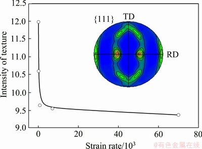
Fig. 8 Effects of strain rates on textures
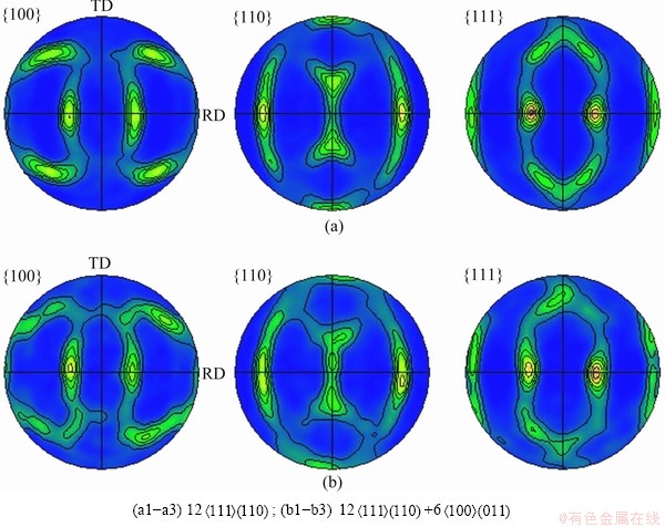
Fig. 9 Effects of slip systems participating calculation on textures on planes {100}, {110} and {111}
5 Conclusions
1) An explicit model controlled by a linear equations set was developed. Crystallographic-system based solving procedure was proposed and the complete pivot Gaussian elimination method was adopted for solution. The model was proved much more efficient (more than 100 time) than the implicit model.
2) The model captures all of the important textures by comparing with the experimental results in the deformation processes as uniaxial compression, uniaxial tension, simple shear and plane-strain compression.
3) {111} plane texture progressed to ��35�� to ND to {111} fiber texture with increasing k. High strain rate does not change texture types but makes textures weak. 12+6 slip systems participating calculation make the predicted texture more relaxed than only 12 slip systems.
References
[1] CHEN Jian, YAN Wen, LI Wei, MIAO Jian, FAN Xin-hui. Texture evolution and its simulation of cold drawing copper wires produced by continuous casting [J]. Transactions of Nonferrous Metals Society of China, 2011, 21(1): 152-158.
[2] ROTERS F, EISENLOHR P, HANTCHERLI L, TJAHJANTO D D, BIELER T R, RAABE D. Overview of constitutive laws, kinematics, homogenization and multiscale methods in crystal plasticity finite-element modeling: Theory, experiments, applications [J]. Acta Materialia, 2010, 58(4): 1152-1211.
[3] KALIDINDI S R, BRONKHORST C A, ANAND L. Crystallographic texture evolution in bulk deformation processing of FCC metals [J]. J Mech Phys Solids, 1992, 40(2): 537-569.
[4] LI H W, YANG H, SUN Z C. A robust integration algorithm for implementing rate dependent crystal plasticity into explicit finite element method [J]. Int J Plasticity, 2008, 24(2): 267-288.
[5]  L X, ZHEN L. Crystal plasticity simulation of polycrystalline aluminum and the effect of mesh refinement on mechanical responses [J]. Mater Sci Eng A, 2011, 528(22-23): 6673-6679.
[6] RAPHANEL J L, RAVICHANDRAN G, LEROY Y M. Three- dimensional rate-dependent crystal plasticity based on Runge-Kutta algorithms for update and consistent linearization [J]. International Journal of Solids and Structures, 2004, 41(22-23): 5995-6021.
[7] PIERCE D, ASARO R J, NEEDLEEMAN A. Material rate dependence and localized deformation in crystalline solids [J]. Acta Metall, 1983, 31(12): 1951-1976.
[8] GRUJICIC M, BATCHU S. Crystal plasticity analysis of earing in deep-drawn OFHC copper cups [J]. J Mater Sci, 2002, 37(4): 753-764.
[9] TAYLOR G I. Plastic strain in metals [J]. Journal of the Institute of Metals, 1938, 62: 307-324.
[10] Van HOUTTE P, DELANNARY L, KALIDINDI S R. Comparison of two grain interaction models for polycrystal plasticity and deformation texture prediction [J]. Int J Plasticity, 2002, 18(3): 359-377.
[11] Van HOUTTE P, LI S, SEEFELDT M, DELANNAY L. Deformation texture prediction: From the Taylor model to the advanced Lamel model [J]. Int J Plasticity, 2005, 21(3): 589-624.
[12] MAHESH S. A binary-tree based model for rate-independent polycrystals [J]. Int J Plasticity, 2010, 26(1): 42-64.
[13] KUMAR M A, MAHESH S, PARAMESWARAN V. A ��stack�� model of rate-independent polycrystals [J]. Int J Plasticity, 2011, 27(6): 962-981.
[14] NEIL C J, AGNEW S R. Crystal plasticity-based forming limit prediction for non-cubic metals: Application to Mg alloy AZ31B [J]. Int J Plasticity, 2009, 25(3): 379-398.
[15] HUANG Shi-yao, ZHANG Shao-rui, LI Da-yong, PENG Ying-hong. Modeling texture evolution during rolling process of AZ31 magnesium alloy with elasto-plastic self consistent model [J]. Transactions of Nonferrous Metals Society of China, 2011, 21(6): 1348-1354.
[16] HUANG Shi-yao, ZHANG Shao-rui, LI Da-yong, PENG Ying-hong. Simulation of texture evolution during plastic deformation of FCC, BCC and HCP structured crystals with crystal plasticity based finite element method [J]. Transactions of Nonferrous Metals Society of China, 2011, 21(8): 1817-1825.
[17] RAABE D, BECKER R C. Coupling of a crystal plasticity finite- element model with a probabilistic cellular automaton for simulating primary static recrystallization in aluminium [J]. Model Simul Mater Sci Eng, 2000, 8(6): 445-462.
[18] ZHOU Y, NEALE K W,  L S. A modified model for simulating latent hardening during the plastic deformation of rate-dependent FCC polycrystals [J]. Int J Plasticity, 1993, 9(8): 961-978.
[19] ABAQUS [M]. Version 6.10. Providence, RI: ABAQUS, Inc., 2010.
[20] BRONKHORST C A, KALIDINDI S R, ANAND L. Polycrystalline plasticity and the evolution of crystallographic texture in FCC metals [J]. Phil Trans R Soc Lond, 1992, A341(1662): 443-477.
���ھ�����������Ԫ�����IJ�ͬ����״̬��֯���ݻ�Ԥ��
������ ��
������ҵ��ѧ ���̼��������ص�ʵ���ң����� 710072
ժ Ҫ�����һ�������Է�����Ϊ���Ʒ��̵���ʽ��������ģ�͡���ģ�Ϳ��ø�˹ȫ��Ԫ��ȥ��ֱ����⣬�����κε�����������ھ���ѧ����ϵ����������Լ������ڱ����о�����ת���������ӵļ�����������������������Ԫģ�ͣ�����Ԥ���������������жԱȣ���֤��ģ����֯���ݻ�Ԥ�ⷽ��Ŀɿ��ԡ���ģ�ͱ�����Ԥ�ⲻͬ����״̬�µ�֯���ݻ�������Щ��ͬ�ı���״̬��ͨ������Z��Y�����ϵļ����ٶȱ�(k)ʵ�ֵġ�ʵ������������ģ����֯���ݻ�Ԥ�ⷽ���ǿɿ���(��ѹ�������졢���к�ƽ��Ӧ��ѹ�������е�Ԥ�����������Ǻ�����)��Ч��(����ʽģ�Ϳ�100�)������kֵ������ǿ֯�����뷨��(ND)�ɡ�35�����{111}���ϵ�˿֯��ת�䣬��֯��ǿ������Ӧ��������0.1~100 s-1֮������ʱ��֯��ǿ��Ѹ�ٽ��ͣ�����Ӧ��������100~7��104 s-1֮������ʱ��֯��ǿ�Ȼ�����С���������ģ����ģ�ⳬ��Ӧ�����ʱ���ʱҲ����ֵ�ȶ��ġ�
�ؼ��ʣ��������ԣ�֯���ݻ�������״̬��Ӧ�����ʣ���ʽģ��
(Edited by DENG -xiang)
Foundation item: Project (2011CB012802) supported by the National Basic Research Program of China; Project (51175428) supported by the National Natural Science Foundation of China; Project (B08040) supported by the Programme of Introducing Talents of Discipline to Universities (��111�� Project)
Corresponding author: LI Hong-wei, Tel: +86-29-88460212; E-mail: lihongwei@nwpu.edu.cn
DOI: 10.1016/S1003-6326(12)61712-9
Abstract: An explicit model controlled by a linear equations set was developed. This model was directly solved by the complete pivot GAUSSIAN elimination method without any iteration. In addition, crystallographic-system based solving procedure was proposed to reduce the additional calculation caused by grain rotation. By establishing crystal plasticity finite element model (CPFEM), the model was verified by comparing the predicted texture to the experimental results. Then, the model was applied to predict textures under different deformation states achieved by adjusting the ratio (k) of the loading velocities in Z and Y directions. The results show that the model is reliable in texture prediction (good agreement with the experiments in compression, tension, simple shear and plane-strain compression) and much more efficient (more than 100 times) than the implicit model; with the increasing of k, the strong texture progresses from ��35�� to normal direction to fiber texture in the {111} plane and enhances in intensity; the texture intensity drops dramatically when the strain rate increases from 0.1 s-1 to 100 s-1, while drops slowly when the strain rate increases from 100 s-1 to 7��104 s-1, which indicates the computational stability of the model for simulation of ultra-high strain rate deformation.
