

J. Cent. South Univ. (2020) 27: 3513-3530
DOI: https://doi.org/10.1007/s11771-020-4469-9

Mechanical properties and reinforcement effect of jointed rock mass with pre-stressed bolt
YANG Wen-dong(���Ķ�), LUO Guang-yu(����), BO Chun-jie(������), WANG Ling(����),
LU Xian-xian(������), WANG Ying-nan(��Ӣ��), WANG Xue-peng(��ѧ��)
College of Pipeline and Civil Engineering, China University of Petroleum, Qingdao 266580, China
 Central South University Press and Springer-Verlag GmbH Germany, part of Springer Nature 2020
Abstract:
Pre-stressed bolt anchorage is the key technology for jointed rock masses in rock tunnelling, slope treatment and mining engineering. To investigate the mechanical properties and reinforcement effect of jointed rock masses with pre-stressed bolts, in this study, uniaxial compression tests were conducted on specimens with different anchoring types and flaw inclination angles. ABAQUS software was used to verify and supplement the laboratory tests. The laws of the uniaxial compressive strength (UCS) obtained from the numerical simulations and laboratory tests were consistent. The results showed that under the same flaw angle, both the UCS and elastic modulus of the bolted specimens were improved compared with those of the specimens without bolts and the improvements increased with an increase in the bolt pre-stress. Under the same anchoring type, the UCS and elastic modulus of the jointed specimens increased with an increase in the flaw angle. The pre-stressed bolt could not only restrain the slip of the specimens along the flaw surface but also change the propagation mode of the secondary cracks and limit the initiation of cracks. In addition, the plot contours of the maximum principal strain and the Tresca stress of the numerical models were influenced by the anchoring type, flaw angle, anchoring angle and bolt position.
Key words:
jointed rock mass; pre-stressed bolt; laboratory test; numerical simulation��
Cite this article as:
YANG Wen-dong, LUO Guang-yu, BO Chun-jie, WANG Ling, LU Xian-xian, WANG Ying-nan, WANG Xue-peng. Mechanical properties and reinforcement effect of jointed rock mass with pre-stressed bolt [J]. Journal of Central South University, 2020, 27(12): 3513-3530.
DOI:https://dx.doi.org/https://doi.org/10.1007/s11771-020-4469-91 Introduction
A rock mass is characterized by a long geological history and is affected by tectonism, weathering and other factors, resulting in the presence of many holes, fissures and joints in the rock mass. These discontinuities develop under the action of a load and make the mechanical properties and failure forms of the rock mass change [1-8]. Bolt support is one of the most effective and common support means for jointed rock masses [9-13]. It has the advantages of a convenient construction, a high adaptability and a low cost and has been widely applied to rock tunnelling, slope treatment and mining engineering since its first application in 1913 [14-16]. Pre-stressed bolts expanded the application scope and scale of bolt support and became the key technology in anchorage engineering [17-19], as they can actively provide the support resistance, obviously improve the shear strength of the structural plane and strengthen the deformati-on control ability to the stratum. Based on the advantages of pre-stressed bolts in terms of working characteristics and mechanical effects, pre-stressed bolts should be used in geotechnical engineering that requires a definite anchoring force to resist vertical displacement, overturning, sliding along the shear plane or large-scale instability [20]. Especially for high-steep slope and deep rock engineering, pre- stressed bolt support is almost the only choice for maintaining the stability of the excavated high- steep slope, and high-strength pre-stressed bolts are often used in the anchorage engineering of deep fractured rock masses. Therefore, studying the mechanical properties and reinforcement effect of jointed rock masses with pre-stressed bolts plays a guiding role in the safety and long-term stability of practical engineering.
The laboratory test is a typical approach for studying the mechanical properties and reinforcement effect of jointed rock mass with bolts, and great progress has also been made in these tests. BJURSTROM [21] was the first to carry out shear tests on the anchoring effect of jointed rock masses and proposed that the bolt restricted the deformation of the jointed rock mass and increased the shear strength of the joint surface. DIGHT [22] used gypsum as a rock-like material to measure the shear strength of the bolted jointed rock mass and established a calculation model to reflect the contribution of bolts to the shear strength of the joint surface. SPANG and EGGER [23] divided the shear stress-displacement curve of the bolt into the elastic stage, yield stage and plastic stage according to the effect of the bolt in different kinds of rock masses. The research of BEZUIJEN [24] showed that the bolted jointed rock mass produced shear displacement under the action of a load, and with an increase in the shear displacement of the joint plane, the plastic hinge would be formed on the bolt, at which time the shear stress on the bolt was the largest. LITTLEJOHN and BRUCE [25] divided the failure mode of a bolted rock mass into three types: rock mass failure, cementation surface failure and bolt failure. YOSHINAKA et al [26] put forward the incremental expression of the shear stiffness of a rock mass caused by a bolt and discussed the factors influencing the anchoring effect of the jointed rock mass based on the experimental study of a bolted jointed rock mass. BARTON and BAKHTAR [27], EGGER and SPANG [28] and GRASSELLI [29] found that the anchoring angle of the bolt affected the reinforcement effect of the rock mass. JALALIFAR and AZIZ [30] and LI et al [31] compared the effects of different types of bolts on the shear strength of rock masses. ZHOU et al [32], WANG and LEI [33] conducted uniaxial compression tests to analyze the anchoring effect of pre-stressed bolts on crack prevention and found that a pre-stressed bolt can restrain the crack propagation. MCHUGH and SIGNER [34] studied the failure mode of the bolt under shear loading and believed that the pre-stress in the bolt had limited the influence on the shear strength of the rock mass.
With the development of the finite element method (FEM), finite difference method (FDM) and discontinuous deformation analysis (DDA), the numerical method is widely used in the analysis of bolted rock masses. For the numerical simulation of rock masses with pre-stressed bolts, there are two main methods: continuum-based methods (CBM) and discontinuum-based methods (DBM). CBM hides the bolt in the common rock element and then transforms the additional stiffness generated by the bolt element into a global stiffness matrix. DBM simulates the physical and mechanical properties of the rock mass and the pre-stressed bolt and applies the pre-stress to the bolt by giving the initial stress or freezing method. MAGHOUS et al [35] described a three-dimensional theoretical and numerical model for rock deformation in bolt-supported tunnels viathe homogenization method. DEB and DAS [36] introduced the mechanical behaviour of rock masses reinforced by a fully grouted rock bolt based on the enriched finite element method (EFEM). SONG et al [37] used a double shear model (DSM) in a numerical simulation on the bolted rock joint shearing performance. NEMCIK et al [38] presented a numerical modelling of fully grouted bolts loaded in tension by implementing the bolt�Cgrout interface into a commercial finite difference rock mechanics code. MA et al [39] proposed a numerical modelling of a mine roadway reinforced with fully encapsulated rock bolts to study the interaction between bolts and rock mass using FLAC2D. TAN [40] presented the solution based on the FDM for the analysis of passive bolt reinforcement around a circular opening. NIE et al [41] coupled a rock bolt element into a two-dimensional discontinuous deformation analysis program to estimate the effectiveness of the rock reinforcement system. LI et al [42] proposed and verified an optimized method using discontinuous deformation analysis for rock failure (DDARF) to perform numerical investigations on the mechanical properties and reinforcement effect of bolted jointed rock masses.
Most of the above studies focused on the influence of ordinary bolts on the mechanical properties of a jointed rock mass. However, there are few studies on the reinforcement effect of a pre-stressed bolt and its influencing factors. Therefore, in this paper, uniaxial compression tests were conducted on jointed rock-like specimens with different anchoring types and flaw inclination angles, and the mechanical parameters and failure modes of each specimen were compared. In addition, ABAQUS software based on the FEM was also employed to conduct a numerical calculation of the jointed rock masses with different anchoring types, flaw inclination angles, anchoring angles and bolt positions under uniaxial compression, which verified and supplemented the laboratory tests.
2 Specimen preparation and testing equipment
The rock-like specimens were made of cement mortar, with cement:sand:water=1:2.34:0.41 in mass. The cement used was C325 Portland cement, and the particle size of the sand was smaller than 4.75 mm. Before the experiment, a uniaxial compression test and a Brazilian split test were conducted on the standard specimens to obtain the mechanical parameters of the rock-like specimen, as shown in Table 1. The pre-stressed bolts were mainly composed of an external anchorage section, a tension section and an internal anchorage section and could be divided into end-anchored and full-length anchorage according to the anchoring length. In this study, pre-stressed bolts with full-length anchorage were selected, as shown in Figure 1. A 6061 aluminium bar was used to simulate the pre-stressed bolt, with a 6 mm diameter and 150 mm length. The thread was processed at both ends of the bar to install and tighten the nuts to ensure the application of the pre- stress. Through a tension test, the tensile strength and elastic modulus of the bar material were 394.49 MPa and 71.33 GPa, respectively.
Table 1 Mechanical parameters of rock-like specimen
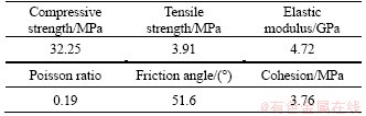
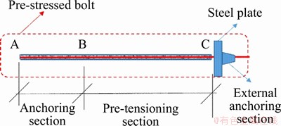
Figure 1 Installation of pre-stressed bolt
To manufacture bolted jointed specimens with different flaw inclination angles, a testing mould was designed, which can pre-set a flaw with multi- angles and accurately locate a bolt. The internal dimensions of the mould were 70 mm��70 mm��140 mm, and a hole was arranged on the long side plate so that the bolt can be inserted into the mould. A set of rectangular positioning plates were composed of two acrylic plates with the same chink, and several sets of positioning plates were designed corresponding to different flaw distribution forms. The flaw was made by embedding a resin sheet in advance. The resin sheet was 0.2 mm thick, and a hole was reserved to ensure the bolt passes through, as shown in Figure 2.
The testing procedure for specimen preparation is as follows. First, the positioning plates corresponding to the flaw angle were placed into the assembled mould, the resin sheet was fixed in the chink of the positioning plate, and the bolt with a strain gauge was passed through the holes on the resin sheet and the side plates. Next, the cement, sand and water were weighed and mixed in a blender for 5 min. Then, the mixture was poured into the mould, which was vibrated. After vibration, the surface of the specimen was smoothed, and the specimen was taken out of the mould after 24 h. Finally, the nuts at both ends of the bolt were tightened to apply pre-stress to the bolt (the pre-stress value was controlled by a strain gauge), and the specimen was cured in water at room temperature for 28 d. Figure 3 shows the photo of a cured specimen.
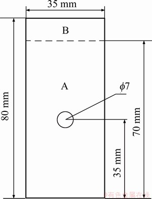
Figure 2 Diagram of resin sheet
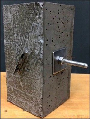
Figure 3 Bolted jointed rock mass specimen
A uniaxial compression test was conducted on the electro-hydraulic servo rigid testing machine. The loading was applied on the specimens via displacement control at a rate of 0.12 mm/min, and the system automatically recorded the pressure and displacement data of the specimens.
3 Experiments
3.1 Experimental conditions
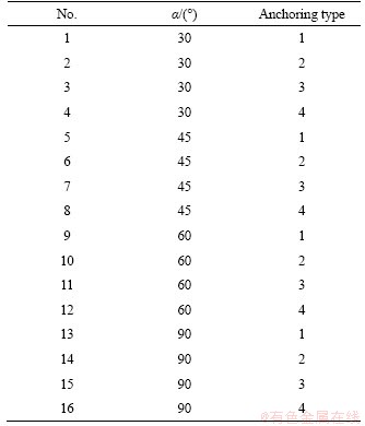
The anchoring type and flaw inclination angle (��) were taken as the testing variables. The angles were 30��, 45��, 60�� and 90��. Specimens with four anchoring types were manufactured: 1) a specimen without a bolt; 2) a specimen with a bolt; 3) a specimen with the pre-stressed bolt at 18 MPa; and 4) a specimen with the pre-stressed bolt at 36 MPa. The specimen configuration is shown in Figure 4, and the experimental conditions are shown in Table 2.
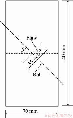
Figure 4 Schematic diagram of specimen configuration
Table 2 Experimental conditions
3.2 Experimental results and analysis
3.2.1 Axial stress-strain curve
The axial stress-strain curves of the specimens with different anchoring types under each flaw inclination angle are shown in Figure 5.
It can be determined from Figure 5 that the axial stress-strain curves of specimens under uniaxial compression can be divided into four stages: the fracture compaction stage, elastic deformation stage, strain hardening stage and strain softening stage. However, the peak strength of the curve and the slope of the elastic stage are different for each specimen due to the difference in the anchoring type and flaw inclination angle. Specifically, under the condition of the same flaw angle, the peak strengths of the bolted specimens are significantly higher than those for specimens without bolts, and the greater the pre-stress value of the bolt is, the higher the peak strength of the specimen is. In addition, for specimens without bolts, the stress drops rapidly after the peak strength, the residual strength is low, and the brittle failure characteristics are significant, but the residual strength of the specimens without a bolt increases with an increase in the flaw angle. In contrast, for bolted specimens, the stress decreases slowly after the peak strength, and the bolt provides the bearing capacity and increases the friction resistance between the fragments, which improves the residual strength of the specimens and makes the specimens show ductile failure characteristics.
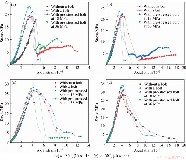
Figure 5 Axial stress-strain curves of specimens:
3.2.2 Uniaxial compressive strength
The uniaxial compressive strengths of the specimens with different flaw inclination angles under each anchoring type are shown in Table 3.
Table 3 Uniaxial compressive strengths of specimens
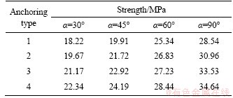
It can be seen from Table 3 that for specimens with the same flaw angle, the UCS of the bolted specimens is higher than that of specimens without bolts, and the UCS of the bolted specimen increases with an increase in the bolt pre-stress. Under the same anchoring type, the larger the flaw angle is, the higher the UCS is.
In this test, the cement mortar simulating rock mass is a brittle material, and the tensile strength is far lower than its compressive strength. Under uniaxial compression, the cracks initiate and rapidly propagate in the specimen, so the specimen is damaged in a short period of time. In contrast, the bolt is made of ductile material with a high tensile strength and shear strength. The bolt embedded in the specimen not only bears tensile stress and shear stress but also improves the friction between the rock particles in the anchoring area. Therefore, the UCS of the bolted specimens is higher than that of the specimens without a bolt. Additionally, the reinforcement effect of the pre-stress in the bolt can be approximately equivalent to the lateral pressure exerted on the specimen along the axis direction of the bolt. For bolted specimens with the same materials, the friction angle and cohesion are equal. Based on Mohr Coulomb theory, the greater the lateral pressure is, the higher the compressive strength of the specimen is. Therefore, the UCS of the bolted specimen increases with an increase in the pre-stress. For specimens under the same anchoring type, with an increase in the flaw inclination angle, the projection area of the flaw perpendicular to the maximum principal stress decreases gradually, which increases the effective bearing area of the specimen. Therefore, the UCS of the jointed specimen increases with an increase in the flaw angle.
3.2.3 Elastic modulus
For specimens with different flaw inclination angles under each anchoring type, the elastic modulus is shown in Table 4.
Table 4 Elastic moduli of specimens
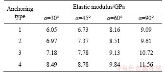
From Table 4, it can be seen that under the condition of the same flaw angle, compared with the specimens without bolts, the elastic modulus of the bolted specimens increases differently, and the greater the pre-stress of the bolt is, the higher the improvement of the elastic modulus. For specimens with the same anchoring type, the elastic modulus increases with an increase in the flaw angle.
For bolted specimens, the bolt passing through the flaw plays a ��pin role��; in other words, it effectively connects the rock on both sides of the flaw, which prevents the specimen from sliding along the structural plane. Moreover, the bolt acts equivalently to applying a lateral restraint force to the specimen, which enhances the ability of the specimen to resist axial deformation, and the lateral force increases with an increase in the bolt pre-stress. Therefore, the elastic modulus of the bolted specimens is higher than that of specimens without bolts, and the elastic modulus of the bolted specimen increases with an increase in the pre-stress. When the anchoring type is the same, the projection area of the flaw in the direction of the maximum principal stress increases gradually with an increase in the flaw inclination angle, which increases the difficulty of the flaw being compressed and improves the elastic modulus of the jointed specimen.
3.2.4 Volume strain curve
Different from pure plastic materials, such as metal, a rock mass is formed via the accumulation or cementation of various minerals. Under the loading, cracks initiate and gradually propagate in the rock mass, resulting in the sum of the lateral strain of the rock exceeding its axial strain and the volume increasing in the compression stage, which is called dilatancy. Dilatancy is a peculiar property of granular materials, and has great influence on the slope stability, displacement of the tunnel surrounding the rock and the bearing capacity of foundation. Therefore, the volume strain of the specimens was analyzed.
Calculate the volume strain of specimens based on Eq. (1).
 (1)
(1)
where ��v is the volume strain; ��x is the lateral strain along the direction of the bolt length; ��y is the lateral strain along the direction of the pre-flaw length; ��z is the axial strain; dx and dz are the lateral displacements along the direction of the bolt length and the axial displacement measured by the sensor; b is the width of the specimen along the direction of the bolt length; and h is the height of the specimen.
The volume strain curves of specimens with different flaw inclination angles under each anchoring type are shown in Figure 6.
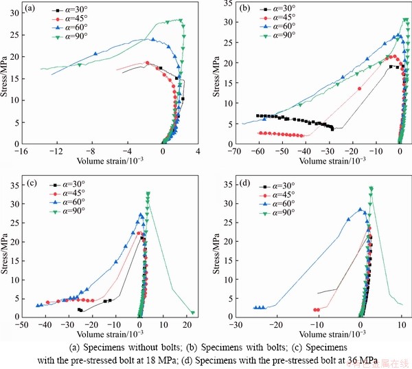
Figure 6 Volume strain curves of specimens:
It can be observed from Figure 6(a) that for the specimens without bolts, at the initial stage of loading, the deformation of the specimen is mainly axial deformation, and the volume strain increases due to the closure of microdefects in the specimen. With an increase in the pressure, the lateral deformation of the specimen increases, leading to a decrease in the volume strain, but the volume strain is still positive because the axial deformation of the specimen is larger than the lateral deformation. Then the specimen slips along the shear plane because of the continuous propagation of cracks in the specimen, which makes the lateral deformation of the specimen increase rapidly and exceed the axial deformation, and the volume strain turns negative. At this time, the dilatancy phenomenon occurs. Additionally, when the flaw inclination angles are 30��, 45��, 60�� and 90��, the corresponding initial dilatancy stress of the specimens without bolts are 16.58, 18.46, 24.67 and 27.91 MPa, respectively. In summary, with an increase in the flaw angle, the ability of the specimens to resist lateral deformation is strengthened, which makes the initial dilatancy stress increase.
From Figures 6(b)-(d), it can be determined that for the bolted specimens, the law of the volume strain can be divided into two types. When the flaw angle is 90�� and the bolt pre-stress is 18 or 36 MPa, the volume strain of the specimen constantly increases. ��y=��x is assumed in Eq. (1), but in fact, the pre-stressed bolt mainly limits the lateral deformation of the specimen along the direction of the bolt length, and the dilatancy phenomenon occurs in the direction of the pre-flaw length, as shown in Figure 7. The variation law of the volume strain of other bolted specimens is similar to that of the specimens without bolts. Specifically, at first the volume strain of the bolted specimens is positive and increasing. Then, the volume strain begins to decrease, but it is still positive. Finally, the volume strain turns negative, and the dilatancy phenomenon occurs. The difference is that the dilatancy of the specimens without a bolt usually occurs before the peak strength, while the dilatancy of the bolted specimens occurs near or after the peak strength because the bolt constrains the lateral deformation of the specimen.
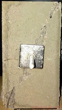
Figure 7 Dilatancy phenomenon in direction of pre-flaw length
3.2.5 Failure mode
The failure modes of the specimens without bolts and the bolted specimens are shown in Figures 8 and 9, respectively. Figure 9(d) selects the side of the bolted specimen for analysis to accurately reflect the failure mode.
From Figure 8, it can be observed that for the specimens without bolts, when the flaw angle is 30�� and 45��, the failure processes of the two specimens are almost the same. Under the action of pressure, the wing cracks first initiate at the tips of the pre-flaw and have an angle of 75��-90�� with the flaw because of the stress concentration and then propagate steadily along the loading direction. After that, the coplanar secondary cracks also initiate at the tips of the flaw, but then coplanar cracks change the development directions and propagate unsteadily to the upper and lower ends of the specimen, which leads to the specimen sliding along the flaw surface. When the flaw angle is 60��, the difference from the two specimens is that the wing crack initiates only at the upper tip of the pre-flaw, and both the coplanar secondary cracks and oblique secondary cracks initiate. When the flaw angle is 90��, the wing cracks first initiateat the tips of the flaw and then propagate rapidly and form the coalescence, which makes the specimen split.
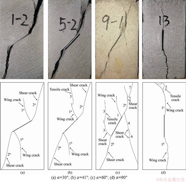
Figure 8 Failure modes of specimens without bolts:
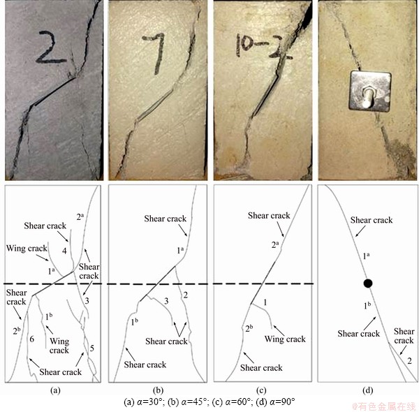
Figure 9 Failure modes of bolted specimens:
It can be determined from Figure 9 that compared with the specimens without bolts, the bolted specimens show different failure characteristics. When the flaw inclination angles are 30��, 45�� and 60��, the ��pin action�� of the bolt can effectively restrain the slip of the specimens along the flaw surface. When the flaw angle is 30��, the oblique secondary crack initiates at the upper tip of the pre-flaw. When the flaw angle is 45��, the bolt improves the stress state of the specimen, which limits the initiation of wing cracks. When the flaw angle is 60��, the bolt changes the propagation law of the coplanar secondary crack at the upper end of the flaw, making it always develop along the pre-flaw plane. Finally, when the flaw angle is 90��, the bolt restrains the initiation of cracks at the tips of the flaw. As shown in Figure 9(d), the cracks initiate at the position where the bolt is embedded on the side of the specimen and coalesce along the diagonal direction on the side.
4 Numerical simulation and discussion
4.1 Establishment of numerical model and conditions of numerical simulation
To verify and supplement the laboratory test, ABAQUS software based on the finite element method was used to conduct the numerical simulation. A cuboid with dimensions of 70 mm�� 70 mm��140 mm was selected as the calculation model of the rock specimens, and the diameter of the bolt was 6 mm. The Mohr Coulomb model and the C3D8R element were adopted for the rock, while the elastic model and the T3D2 element were selected for the bolt.
The yield surface of the Mohr-Coulomb plasticity model is a composite of two different criteria: a shear criterion, known as the Mohr- Coulomb surface, and an optional tension cutoff criterion, modeled using the Rankine surface.
The Mohr-Coulomb criterion assumes that yield occurs when the shear stress on any point in a material reaches a value that depends linearly on the normal stress in the same plane.For general states of stress, the criterion is written in terms of three stress invariants as
 (2)
(2)
 (3)
(3)
where �� and c are the friction angle and the cohesion of the material respectively; �� is the deviatoric polar angle; p is the equivalent pressure stress and q is the Mises equivalent stress.
In Abaqus, tension cutoff is modeled using the Rankine surface, which is written as
 (4)
(4)
where ��t is the tension cutoff value.
The flow potential for the Mohr-Coulomb yield surface is chosen as a hyperbolic function in the meridional stress plane and the smooth elliptic function in the deviatoric stress plane:
 (5)
(5)

 (6)
(6)
where �� is the dilation angle, c0 is the initial cohesion yield stress, �� is a parameter about the meridional eccentricity and e is a parameter about the deviatoric eccentricity.
A flow potential that results in a nearly associative flow is chosen for the Rankine surface:
 (7)
(7)


 (8)
(8)
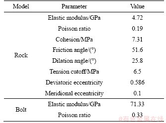
where ��t0 is the initial value of tension cutoff; ��t is the meridional eccentricity similar to �� defined earlier; and et is the deviatoric eccentricity similar to e defined earlier. The mechanical parameters of the model are listed in Table 5.
Table 5 Mechanical parameters of model
An embedded constraint was used to simulate the coupling between the bolt and the jointed rock mass. Figure 10 shows the calculation model. During a test, the lower surface of the specimen was fixed, and the loading was applied on the upper surface via displacement control. The central point of the upper surface was set as the monitoring point during the calculation. Based on Eq. (9), pre-stress was applied by reducing the temperature to make the bolt contract.
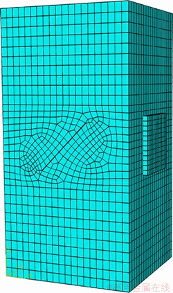
Figure 10 Calculation model
��b=�ȡ�E����T (9)
where ��b is the pre-stress of the bolt; �� is the expansion coefficient; E is the elastic modulus and ��T is the reduction value of the temperature.
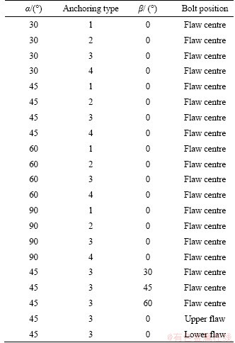
The influences of the anchoring type, flaw inclination angle (��), anchoring angle (��) and bolt position on the mechanical properties and reinforcement effect of a jointed rock mass with a pre-stressed bolt were analyzed. The conditions of the numerical simulation are shown in Table 6. Among them, upper flaw, flaw centre and lower flaw representing the central axis of the bolt are located at the upper boundary, the centre and the lower boundary of the flaw, respectively.
Table 6 Conditions of numerical simulation
4.2 Results of numerical simulation
4.2.1 Comparison of measured values and numerical simulation results
Figure 11 demonstrates the uniaxial compressive strength of the numerical simulation corresponding to the laboratory tests.
Compared with Figure 11 and Table 3, it can be seen that for uniaxial compressive strength, the numerical simulation results are consistent with measured values, which proves the rationality of the test results and the applicability of the numerical calculation. When the flaw inclination angles are 30��, 45�� and 60��, the numerical results are slightly larger than the test results, but the gap between the two is small. However, when the flaw angle is 90��, the numerical simulation results are significantly larger than the measured values, and the gap between the two is large. This is because the Mohr Coulomb model based on shear failure was adopted to simulate the rock in the numerical calculation, but splitting failure occurs when the flaw angle of the specimen is 90��.
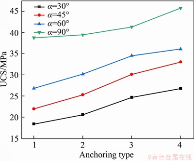
Figure 11 Uniaxial compressive strength of calculation models
4.2.2 Influence of anchoring type
Taking the models with a flaw inclination angle of 45�� and an anchoring angle of 0�� as examples, the influence of the anchoring type on the jointed rock mass was studied. Plot contours of the maximum principal strain of each numerical model at the same time are shown in Figure 12. The plot contours of the Tresca stress of the models when the axial stress at the monitoring point reaches the peak strength is shown in Figure 13, which can reflect the ability of the model to resist shear failure.
It can be seen from Figure 12 that the maximum principal strain of each model is tensile strain at all positions, and a larger maximum principal strain is distributed near the flaw tips and spreads to the boundaries of the modelat 60��-75�� along the horizontal direction. For the model without a bolt and the model with an ordinary bolt, the larger maximum principal strain is distributed in the lower left and upper right of the flaw and the maximum value of the maximum principal strain appears in the upper right of the flaw. For the models with a pre-stressed bolt, the larger maximum principal strain is distributed in the upper left and lower right of the flaw and the maximum value of the maximum principal strain exists in the upper left of the flaw. Moreover, the maximum principal strain of the bolted models is smaller than that of the model without a bolt, and the maximum principal strain decreases gradually with an increase in the bolt pre-stress, which reflects the restriction effect of the pre-stressed bolt on the tensile deformation of the rock mass.
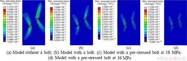
Figure 12 Plot contours of the maximum principal strain of models under different anchoring types:
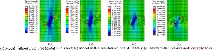
Figure 13 Plot contours of Tresca stress of models under different anchoring types:
From Figure 13, it can be determined that the largest Tresca stress of the numerical models is at the flaw tips and that the Tresca stress in the middle of the model is smaller than that around the model. Compared with the model without a bolt, the average Tresca stress of the bolted models is larger, and the distribution range of the minimum Tresca stress is smaller. Additionally, with an increase in the bolt pre-stress, the average Tresca stress increases, and the range of the minimum Tresca stress decreases. The differences illustrate that the pre-stressed bolt increases the shear strength of the rock mass.
4.2.3 Influence of flaw inclination angle
Models with the pre-stressed bolt at 18 MPa and an anchoring angle of 0�� were generated to study the influence of the flaw inclination angle on bolted jointed rock mass, which can be found in Figures 14 and 15.
It can be observed from Figure 14 that the maximum principal strain of the models is tensile strain at all positions. When the flaw angle is 30��, 45�� and 60��, the larger maximum principal strain is distributed in the lower left and upper right of the flaw. When the flaw angle is 30��, the maximum value of the maximum principal strain exists in the lower left of the flaw. When the flaw angle is 45�� and 60��, the maximum value is located in the upper right of the flaw. When the flaw angle is 90��, the maximum principal strain values of the model at each position have little difference because the influence of the flaw on the model is small, and the maximum value appears near the bottom of the model. In addition, the maximum and average values of the maximum principal strain of the model decrease with an increase in the flaw angle.
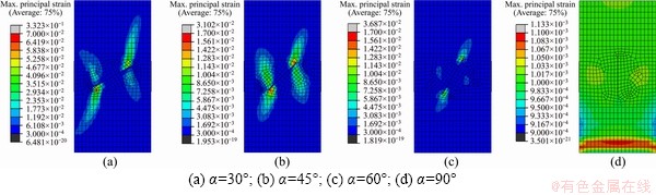
Figure 14 Plot contours of the maximum principal strain of models under different flaw inclination angles:
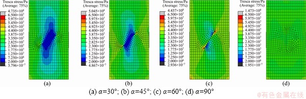
Figure 15 Plot contours of Tresca stress of models under different flaw inclination angles:
From Figure 15, it can be observed that for the models with a flaw angle of 30��, 45�� and 60��, the largest Tresca stress appears at the flaw tips, and the Tresca stress in the middle of the model is smaller than that around the model. With an increase in the flaw angle, the distribution range of the minimum Tresca stress decreases. For the model witha flaw angle of 90��, the distribution of the Tresca stress is not obvious, and the largest Tresca stress exists at two corners of the model. Moreover, the average Tresca stress of the model increases with an increase in the flaw angle.
4.2.4 Influence of anchoring angle
The influence of the anchoring angle on the bolted rock mass was studied by taking the models with a flaw inclination angle of 45�� and a pre-stressed bolt at 18 MPa. The uniaxial compressive strength of each model is shown in Figure 16.
Figure 16 shows that with an increase in the anchoring angle, the UCS of the numerical model decreases first and then increases. The UCS of the model is the largest when the anchoring angle is 0��,and the UCS is the smallest when the anchoring angle is 45��. The plot contours of the maximum principal strain of the numerical models at the same time are shown in Figure 17, and the plot contours of the Tresca stress of the models when the axial stress at the monitoring point reaches the peak strength are shown in Figure 18.
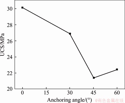
Figure 16 Uniaxial compressive strength-anchoring angle curve of models
It can be determined from Figure 17 that the maximum principal strain of the models is tensile strain in all regions. When the anchoring angle is 0��, the larger maximum principal strain is distributed in the upper left and the lower right of the flaw and the maximum value of the maximum principal strain is located in the upper right of the flaw. When the anchoring angle is 30��, 45�� and 60��, the larger maximum principal strain appears in the lower left and the upper right of the flaw and develops to the boundaries of the model at approximately 75�� along the horizontal direction, and the maximum value exists in the upper right of the flaw. In addition, the maximum and average values of the model increases first and then decreases with an increase in the anchoring angle. When the anchoring angle is 0��, the maximum and average values are the smallest; and when the anchoring angle is 30��, the values are the largest.
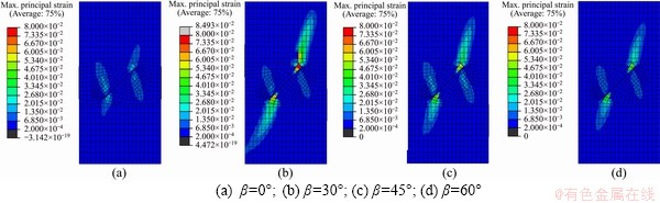
Figure 17 Plot contours of the maximum principal strain of models under different anchoring angles:
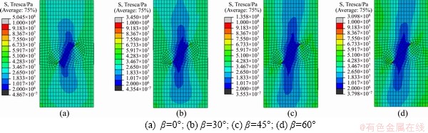
Figure 18 Plot contours of Tresca stress of models under different anchoring angles:
Figure 18 demonstrates that the largest Tresca stress of each numerical model is distributed at the flaw tips, and the Tresca stress around the model is greater than that in the middle of the model. It can also be seen that the average Tresca stress of the model decreases first and then increases with an increase in the anchoring angle.
4.2.5 Influence of bolt position
The models with a flaw inclination angle of 45�� and an anchoring angle of 0�� reinforced by the pre-stressed bolt at 18 MPa were established. Based on the samples, the influence of the bolt position was studied. The uniaxial compressive strength of the bolted models is shown in Figure 19, where 1, 2 and 3 represent that the bolt is located at the upper part, the centre and the lower part of the flaw, respectively.
Figure 19 shows that the closer the pre-stressed bolt is to the bottom of the model, the greater the UCS is because the lower surface of the model is the fixed boundary; when the distance between the anchoring zone and the fixed boundary is shortened, the stability of the bolted rock mass is enhanced. The plot contours of the maximum principal strain and the Tresca stress are shown in Figures 20 and 21, respectively.
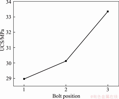
Figure 19 Uniaxial compressive strength�Cbolt position curve of models
It can be observed from Figure 20 that when the bolt is located at the centre of the flaw, the larger maximum principal strain is distributed in the upper left and lower right of the flaw and the maximum value of the maximum principal strain exists in the upper left of the flaw. When the bolt is located at the upper part of the flaw, the maximum principal strain is smaller at the upper part of the flaw and the maximum value is located in the lower right of the flaw. When the bolt is located at the lower part of the flaw, the maximum principal strain is smaller at the lower part of the flaw and the maximum value appears in the upper left of the flaw. Moreover, when the bolt is located at the lower part of the flaw, the maximum value of the maximum principal strain is the largest, and when the bolt is located at the centre of the flaw, the maximum value is the smallest.
Figure 21 illustrates that the largest Tresca stress of the numerical models exists at the flaw tips and the Tresca stress around the model is larger than that in the middle of the model. Additionally, with a decrease in the distance between the bolt and the model bottom, the distribution range of the minimum Tresca stress decreases, but the average Tresca stress of the model increases.
5 Conclusions
In this paper, uniaxial compression tests were conducted on jointed rock-like specimens with pre-stressed bolts to investigate their mechanical properties and failure modes. ABAQUS software based on the FEM was also employed to verify and supplement the laboratory tests. The following conclusions were drawn from this study.
1) Under the conditions of the same flaw inclination angle, the UCS and elastic modulus of the bolted specimens both have different improvements compared with those of the specimens without bolts, and the improvements increase with an increase in the bolt pre-stress. For the jointed specimens with the same anchoring type, the UCS and elastoc modulus increase with an increase in the flaw angle.
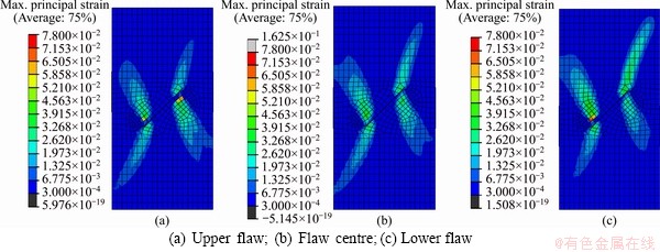
Figure 20 Plot contours of the maximum principal strain of models under different bolt positions:

Figure 21 Plot contours of Tresca stress of models under different bolt positions:
2) The dilatancy of the specimens without a bolt usually occurs before the peak strength, and the initial dilatancy stress increases with an increase in the flaw angle. For specimens with a flaw angle of 90�� reinforced by the pre-stressed bolt at 18 MPa or 36 MPa, the dilatancy phenomenon occurs in the direction of the pre-flaw length. For the other bolted specimens, dilatancy occurs near or after the peak strength.
3) For the specimens without bolts, the propagation directions of the coplanar secondary cracks are changed, leading to the sliding of the specimen along the flaw surface when the flaw angle is 30��, 45�� and 60��, while the wing cracks propagate rapidly and form the coalescence, causing the specimen to split when the flaw angle is 90��. The pre-stressed bolt can not only restrain the slipof the specimens along the flaw surface but also change the development mode of the secondary cracks and limit the initiation of cracks.
4) Under different anchoring types and flaw inclination angles, the law of the UCS obtained from the numerical simulations and the laboratory tests is consistent. Additionally, the numerical simulation results show that with an increase in the anchoring angle, the UCS of the model first decreases and then increases, with a decrease in the distance between the bolt and the model bottom, the UCS of the model increases gradually. It can also be determined that the distribution of the maximum principal strain and the Tresca stress in the calculation models is affected by the anchoring type, flaw angle, anchoring angle and bolt position.
Nomenclature
b
The width of the specimen along the direction of the bolt length
c
The cohesion of the material
c0
The initial cohesion yield stress
dx
The lateral displacement along the direction of the bolt lengthmeasured by the sensor
dz
The axial displacement measured by the sensor
e
A parameter about the deviatoric eccentricity
E
The elastic modulus
h
The height of the specimen
p
The equivalent pressure stress
q
The Mises equivalent stress
UCS
Uniaxial compressive strength
��b
The pre-stress of the bolt
��t
The tension cutoff value
��v
The volume strain
��x
The lateral strain along the direction of the bolt length
��y
The lateral strain along the direction of the pre-flaw length
��z
The axial strain
��
The friction angle of the material
��
The deviatoric polar angle
��
The dilation angle
��
A parameter about the meridional eccentricity
��
The expansion coefficient
��T
The reduction value of the temperature
Contributors
The overarching research goals were developed by YANG Wen-dong and LUO Guang-yu. BO Chun-jie and WANG Ling analyzed the calculated results. LU Xian-xian, WANG Ying-nan and WANG Xu-peng carried out the experiments and analyzed the measured data. The initial draft of the manuscript was written by YANG Wen-dong and LUO Guang-yu.
Conflict of interest
YANG Wen-dong, LUO Guang-yu, BO Chun-jie, WANG��Ling, LU Xian-xian, WANG Ying-nan and WANG Xu-peng declare that they have no conflict of interest.
References
[1] ZHOU Jun-hua, YANG Kun, FANG Kai, ZHAO Tong-bin, QIU Dong-wei. Effect of fissure on mechanical and damage evolution characteristics of sandstone containing hole defect [J]. Journal of Central South University (Science and Technology), 2019, 50(4): 968-975. DOI: 10.11817/j.issn. 1672-7207.2019.04.026. (in Chinese)
[2] YANG Sheng-qi, HUANG Yan-hua, TIAN Wen-ling, ZHU Jian-bo. An experimental investigation on strength, deformation and crack evolution behavior of sandstone containing two oval flaws under uniaxialcompression [J]. Eng Geol, 2017, 217: 35-48. DOI: https://doi.org/10.1016/ j.enggeo.2016.12.004.
[3] YANG Wen-dong, LI Gui-zhi, RANJITH P G, FANG Lin-dong. An experimental study of mechanical behavior of brittle rock-like specimens with multi-non-persistent joints under uniaxial compression and damage analysis [J]. Int J Damage Mech, 2019, 28(10): 1490-1522. DOI: 10.1177/ 1056789519832651.
[4] YANG Xu-xu, JING Hong-wen, TANG Chun-an, YANG Sheng-qi. Effect of parallel joint interaction on mechanical behavior of jointed rock mass models [J]. Int J Rock Mech Min Sci, 2017, 92: 40-53. DOI: 10.1016/j.ijrmms.2016. 12.010.
[5] WU Fa-quan, DENG Yi, WU Jie, LI Bo, SHA Peng, GUAN Sheng-gong, ZHANG Kai, HE Ke-qiang, LIU Han-dong, QIU Shu-hao. Stress�Cstrain relationship in elastic stage of fractured rock mass [J]. Eng Geol, 2020, 268: 1-8. DOI: 10.1016/j.enggeo.2020.105498.
[6] HUANG Chen-chen, YANG Wen-dong, DUAN Kang, FANG Lin-dong, WANG Ling, BO Chun-jie. Mechanical behaviors of the brittle rock-like specimens with multi-non- persistent joints under uniaxial compression [J]. Constr Build Mater, 2019, 220: 426-443. DOI: 10.1016/j.conbuildmat. 2019.05.159.
[7] ZHOU T, ZHU J B, JU Y, XIE H P. Volumetric fracturing behavior of 3D printed artificial rocks containing single and double 3D internal flaws under static uniaxial compression [J]. Eng Fract Mech, 2019, 205: 190-204. DOI: 10.1016/ j.engfracmech.2018.11.030.
[8] YANG Wen-dong, ZHANG Qian-bing, RANJITH P G, YU Ran-gang, LUO Guang-yu, HUANG Chen-chen, WANG Gang. A damage mechanical model applied to analysis of mechanical properties of jointed rock masses [J]. Tuun Undergr Space Tech, 2019, 84: 113-128. DOI: 10.1016/ j.tust.2018.11.004.
[9] CUI Guo-jian, ZHANG Chuan-qing, CHEN Jian-lin, YANG Fan-jie, ZHOU Hui, LU Jing-jing. Effect of bolt inclination angle on shear behavior of bolted joints under CNL and CNS conditions [J]. Journal of Central South University, 2020, 27: 937-950. DOI: https://doi.org/10.1007/s11771-020-4342-x.
[10] WANG Q, QIN Q, JIANG B, YU H C, PAN R, LI S C. Study and engineering application on the bolt-grouting reinforcement effect in underground engineering with fractured surrounding rock [J]. Tunn Undergr Space Technol, 2019, 84: 237-247. DOI: 10.1016/j.tust.2018.11.028.
[11] ZHANG Bo, LI Shu-cai, XIA Kai-wen, YANG Xue-ying, ZHANG Dun-fu, WANG Shu-gang, ZHU Jian-bo. Reinforcement of rock mass with cross-flaws using rock bolt [J]. Tunn Undergr Space Technol, 2016, 51: 346-353. DOI: 10.1016/j.tust.2015.10.007.
[12] SRIVASTAVA L P, SINGH M. Empirical estimation of strength of jointed rocks traversed by rock bolts based on experimental observation [J]. Eng Geol, 2015, 197: 103-111. DOI: 10.1016/j.enggeo.2015.08.004.
[13] LI C C. Principles of rockbolting design [J]. J Rock Mech Geotech Eng, 2017, 9(3): 396-414. DOI: 10.1016/j.jrmge. 2017.04.002.
[14] MOHAMMADI M, HOSSAINI M F, BAGLOO H. Rock bolt supporting factor: Rock bolting capability of rock mass [J]. Bulletin of Engineering Geology and the Environment, 2017, 76(1): 231-239. DOI: 10.1007/s10064-015-0785-y.
[15] ZOU Jin-feng, XIA Zhang-qi, DAN Han-cheng. Theoretical solutions for displacement and stress of a circular opening reinforced by grouted rock bolt [J]. Geomech Eng, 2016, 11(3): 439-455. DOI: 10.12989/gae.2016.11.3.439.
[16] ZHU Wen-xin, JING Hong-wen, YANG Li-jun, PAN Bing, SU Hai-jian. Strength and deformation behaviors of bedded rock mass under bolt reinforcement [J]. Int J Min Sci Technol, 2018, 28: 593-599. DOI: 10.1016/j.ijmst.2018.03. 006.
[17] DANZIGER F A B, DANZIGER B R, PACHECO M P. The simultaneous use of piles and prestressed anchors in foundation design [J]. Eng Geol, 2006, 87(3): 163-177.
[18] KUMAR R, SHARMA K G, VARADARAJAN A. Post-peak response of some metamorphic rocks of India under high confining pressures [J]. Int J Rock Mech Min Sci, 2010, 47(8): 1357-1362. DOI: 10.1016/j.ijrmms.2010.08.016.
[19] CHUNG K. Prediction of pre- and post-peak behavior of concrete-filled circular steel tube columns under cyclic loads using fiber element method [J]. Thin Wall Struct, 2010, 48(2): 169-178. DOI: 10.1016/j.tws.2007.06.003.
[20] CHENG Liang-kui, ZHANG Pei-wen, WANG Fan. Several mechanical concepts for anchored structures in rock and soil [J]. Chin J Rock Mech Eng, 2015, 34(4): 668-682. DOI: 10.13722/j.cnki.jrme.2015.04.000. (in Chinese)
[21] BJURSTROM S. Shear strength of hard rock joints reinforced by grouted un-tensioned bolts [C]// Proceedings of the 3rd International Congress on Rock Mechanics. Denver, 1974, 2: 1194-1199.
[22] DIGHT P M. Improvements to the stability of rock walls in open mines [D]. Australia: Monash University, 1982.
[23] SPANG K, EGGER P. Action of fully-grouted bolt in jointed rock and factors of influence [J]. Rock Mech Rock Eng, 1990, 23(3): 201-229. DOI: 10.1007/bf01022954.
[24] BEZUIJEN A. Compensation grouting in sand: Experiments, field experiences and mechanisms [D]. Delft: Delft University of Technology, 2010.
[25] LITTLEJOHN G S, BRUCE D A. Rock anchors: State-of- the-art part I, design, ground engineering [M]. Essex, England: Foundation Publications Ltd., 1975: 163-175.
[26] YOSHINAKA R, SKAGUCHI S, SHIMIZU T. Experimental study on the rock bolt reinforcement in discontinuous rock [J]. Electr Commun JPN, 1987, 133(113): 117-127. DOI: info:doi/10.1002/ecj.11645.
[27] BARTON N, BAKHTAR K. Bolt design based on shear strength [C]// Proceedings of the International Symposium on Rock Bolting. Stockholm, Balkema, 1983: 367-376.
[28] EGGER P, SPANG K. Stability investigations for ground improvement by rock bolt at a large dam [C]// Proceedings of VI International Conference ISRM. Montreal, Canada, 1987: 349-354.
[29] GRASSELLI G. 3D behaviour of bolted rock joints: Experimental and numerical study [J]. Int J Rock Mech Min Sci, 2005, 42(11): 13-24. DOI: 10.1016/j.ijrmms.2004.06. 003.
[30] JALALIFAR H, AZIZ N. Experimental and 3D numerical simulation of reinforced shear joints [J]. Rock Mech Rock Eng, 2010, 43(1): 95-103. DOI: 10.1007/s00603-009-0031- 7.
[31] LI Xu-wei, AZIZ N, MIRZAGHORBANALI A, NEMCIK J. Behavior of fiber glass bolts, rock bolts and cable bolts in shear [J]. Rock Mech Rock Eng, 2016, 49: 2723-2735. DOI: https://doi.org/10.1007/s00603-015-0907-7.
[32] ZHOU Hui, XU Rong-chao, ZHANG Chuan-qing, SHEN Zheng, MENG Fan-zhen, LIU Hai-tao. Experimental study of crack prevention effect of pre-stressed bolt anchoring [J]. Chin J Rock Mech Eng, 2015, 34(10): 2027-2037. DOI: 10.13722/j.cnki.jrme.2015.0983. (in Chinese)
[33] WANG Chuan-bing, LEI Guang-feng. Experimental study on bolt anchorage affected to mechanics features of fractured rock mass [J]. Mine Construction Technology, 2017, 38(2): 23-29. (in Chinese)
[34] MCHUGH E L, SIGNER S P. Roof bolt response to shear stress: Laboratory analysis [C]// Proceedings of 18th International Conference on Ground Control in Mining. Morgantown, USA, 1999: 232-238.
[35] MAGHOUS S, BERNAUD D, COUTO E. Three- dimensional numerical simulation of rock deformation in bolt-supported tunnels: A homogenization approach [J]. Tunn Undergr Sp Tech, 2012, 31: 68-79. DOI: 10.1016/j.tust. 2012.04.008.
[36] DEB D, DAS K C. Modelling of fully grouted rock bolt based on enriched finite element method [J]. Int J Rock Mech Min Sci, 2011, 48(2): 283-293. DOI: 10.1016/ j.ijrmms.2010.11.015.
[37] SONG Hong-wei, DUAN Yan-yan, YANG Jing. Numerical simulation on bolted rock joint shearing performance [J]. Mining Science and Technology, 2010, 20(3): 460-465. DOI: https://doi.org/10.1016/j.jrmge.2017.04.002.
[38] NEMCIK J, MA Shu-qi, AZIZ N, REN Ting, GENG Xue-yu. Numerical modelling of failure propagation in fully grouted rock bolts subjected to tensile load [J]. Int J Rock Mech Min Sci, 2014, 71: 293-300. DOI: 10.1016/j.ijrmms.2014.07.007.
[39] MA Shu-qi, NEMCIK J, AZIZ N. Simulation of fully grouted rockbolts in underground roadways using FLAC2D [J]. Can Geotech J, 2014, 51(8): 911-920. DOI: 10.1139/cgj- 2013-0338.
[40] TAN Cheng-hua. Difference solution of passive bolts reinforcement around a circular opening in elastoplastic rock mass [J]. Int J Rock Mech Min Sci, 2016, 81: 28-38. DOI: 10.1016/j.ijrmms.2015.11.001.
[41] NIE W, ZHAO ZY, NING YJ, SUN JP. Development of rock bolt elements in two-dimensional discontinuous deformation analysis [J]. Rock Mech Rock Eng, 2014, 47: 2157-2170. DOI: 10.1007/s00603-013-0525-1.
[42] LI Yong, ZHOU Hao, ZHANG Lei, ZHU Wei-shen, LI Shu-cai, LIU Jian. Experimental and numerical investigations on mechanical property and reinforcement effect of bolted jointed rock mass [J]. Constr Build Mater, 2016, 126: 843-856. DOI: 10.1016/j.conbuildmat.2016.09. 100.
(Edited by HE Yun-bin)
���ĵ���
ԤӦ��ê�˼ӹ���϶������ѧ���ʼ�ê��Ч���о�
ժҪ��������������������������ɽ�����У�ԤӦ��ê���Ǽӹ̽�������Ĺؼ�������Ϊ�о�ԤӦ��ê�˼ӹ���϶�������ѧ���ʺ�ê��Ч�������ĶԲ�ͬê�̷�ʽ����϶��ǵ�������չ����ѹ������,������ABAQUS�������������������֤�Ͳ��䣬������ֵģ�����������õ��ĵ���ѹ��ǿ�ȹ���һ�¡��������������϶�����ͬʱ���������ê��������ê�����ĵ���ѹ��ǿ�Ⱥ͵���ģ����������ߣ�����̶߳�����ê��ԤӦ�������Ӷ������ӣ�����ͬ��ê�̷�ʽ�£���϶�����ĵ���ѹ��ǿ�Ⱥ͵���ģ��������϶��ǵ����Ӷ���ߡ�ԤӦ��ê�˲�������������������϶�淢�����廬���������ܹ��ı�������Ƶ���չģʽ���������Ƶ��γɡ����⣬ê�̷�ʽ����϶��ǡ�ê�̽ǶȺ�ê��λ�ö���ֵģ�͵������Ӧ����ͼ��TrescaӦ����ͼ���Ų�ͬ�̶ȵ�Ӱ�졣
�ؼ��ʣ��������壻ԤӦ��ê�ˣ��������飻��ֵģ��
Foundation item: Project(51979281) supported by the National Natural Science Foundation of China; Project(ZR2018MEE050) supported by the Natural Science Foundation of Shandong Province, China; Project(18CX02079A) supported by the Fundamental Research Funds for the Central Universities, China
Received date: 2020-04-14; Accepted date: 2020-07-04
Corresponding author: YANG Wen-dong, PhD, Associate Professor; Tel: +86-15376713557; E-mail: yangwd@upc.edu.cn; ORCID: https://orcid.org/0000-0001-8398-4014
Abstract: Pre-stressed bolt anchorage is the key technology for jointed rock masses in rock tunnelling, slope treatment and mining engineering. To investigate the mechanical properties and reinforcement effect of jointed rock masses with pre-stressed bolts, in this study, uniaxial compression tests were conducted on specimens with different anchoring types and flaw inclination angles. ABAQUS software was used to verify and supplement the laboratory tests. The laws of the uniaxial compressive strength (UCS) obtained from the numerical simulations and laboratory tests were consistent. The results showed that under the same flaw angle, both the UCS and elastic modulus of the bolted specimens were improved compared with those of the specimens without bolts and the improvements increased with an increase in the bolt pre-stress. Under the same anchoring type, the UCS and elastic modulus of the jointed specimens increased with an increase in the flaw angle. The pre-stressed bolt could not only restrain the slip of the specimens along the flaw surface but also change the propagation mode of the secondary cracks and limit the initiation of cracks. In addition, the plot contours of the maximum principal strain and the Tresca stress of the numerical models were influenced by the anchoring type, flaw angle, anchoring angle and bolt position.
