
DOI: 10.11817/j.issn.1672-7207.2018.09.028
�����������ģ�͵ĸ߹����ܶ���ȼ�����ڴ���ģ��
����1��������2����ǿ1��Ф����1��������1�����Ѻ�1
(1. �㽭��ѧ����ѧԺ ����ѧԺ���㽭 ���ݣ�310015��
2. �㽭��ѧ ��Դ����ѧԺ���㽭 ���ݣ�310027)
ժ Ҫ��
��ʽ�������ڸ߹����ܶ���ȼ�����ȱ߽���ص����⣬��WOSCHNI��ʽΪ����������������������ֵ���㷽������������ڸ������ܶ���ȼ�����ڴ��ȵİ뾭�鹫ʽ����ij�����������Ϊ����������-������ά��̬��Ϸ���ϵͳ������Fluent����������ֵ��⣬�����ý���������������������жԱȡ��о�����������ڸ߹����ܶ������������������ϣ�4�������·����������������������5%���ڡ���ˣ���������İ뾭�鹫ʽ�뽨�����������ģ���ܹ��Ϻõ�ģ����ȼ����̬���ȡ�
�ؼ��ʣ�
��ȼ�����߹����ܶ��������������̬���������ڴ���ģ����
��ͼ����ţ�TK41/TK42 ���ױ�־�룺A ���±�ţ�1672-7207(2018)09-2330-07
Heat transfer model for high power density internal combustion engine based on fluid-solid coupling model
ZHANG Yu1, LIU Zhentao2, ZUO Qiang1, XIAO Baolan1, SUN Shuli1, FU Jiahong1
(1. School of Engineering, Zhejiang University City College, Hangzhou 310015, China;
2. Department of Energy Engineering, Zhejiang University, Hangzhou 310027, China)
Abstract: For the problem that semi-empirical formula is not suitable for the heat transfer boundary condition of high power density internal combustion engine, the revised semi-empirical formula for heat transfer in this model was proposed based on the Woschni formula and the numerical calculation method of fluid-solid coupling. Taking a single cylinder test machine as an example, a three-dimensional steady-state coupled simulation system of head-sleeve was established. The numerical model was solved using Fluent software, and the results were compared with temperature test results of the whole engine. The results show that the relative error between simulation and experiment results is less than 5% under four conditions at power characteristics curve of high power density prototype. Therefore, the semi-empirical formula proposed and the fluid-solid coupling model established in this paper can well simulate the steady-state heat transfer of internal combustion engine.
Key words: internal combustion engine; high power density; fluid-solid coupling; steady-state heat transfer; in-cylinder heat transfer model
��ȼ��ȼ����������¶ȼ���ֲ�ֱ�Ӿ�������ɿ��Լ�������ͬʱӰ�����ȼ�չ����Լ��ŷ����ԣ���ˣ�ȼ��������¶ȳ�Ԥ������ȼ����Ƶ���Ҫ���ڡ�������漰��ȼ���������̡�ȼ��������IJ��ϡ��ṹ�Լ���ȴ��ʽ��������ص�������ã����У����ڸ��ڹ���ʮ�ָ��ӣ��йظ��ڴ��ȵ��о�һֱ��ҵ���ע�Ľ��㡣����ʮ���������ڴ���ģ�ʹ��¾�����3���Σ�������ģ�ͽΡ���������ԭ�������ٷ����İ뾭��ģ�ͽ�[1-2]������������ģ�ͽ�[3-7]��Ŀǰ����Ϊ���õ���WOSCHNI��HUBER��HOHENBERG���ܽ���������ʽ�������о��߲��϶������������BROEKAERT��[8-9]�ֱ��������CH4��H2��CH3OHΪȼ�ϵķ������ڵ��Ϻ͵����Ԥ��ȼ��ʱ�������ܶȣ��������������Զ�������Ӱ����ɣ�У�鲢�Ľ���REYNOLDS����ģ�ͣ��������Բ���ϴ���ȼ�Ϸ������������ܶȱ�̼��ȼ�ϵĸߣ���ͳģ��������Ҫ��MICHL��[10]���ÿ�����Ӧ�ȵ�ż������ȼ���ұ��������ܶȣ��Ľ��˴���ģ��ʹ��Ԥ�⾫���ڸ��ֹ����¾��ϸߣ�FAGUNDEZ��[2]�����˲�ͬ�����ĺ�ˮ�Ҵ���ȼ�չ��̣���������WIEBE����Ϊ����������ȼ��ģ�ͣ��Ա�WOSCHNI��HOHENBERG��SITKEI��ANNAND�ȴ��ȹ���ʽ������HOHENBERG��ʽ��Ԥ�⾫����ߣ������������ݵĻ����ϵ�����ģ�Ͳ������ɴ˿�֪��������ȼ���������ٷ�չ���뾭��ģ���е���Ӧ������Ҫ���Ͻ��е������Ӷ���Ӧ�»����¶ȳ���Ԥ�⡣Ȼ������ĿǰΪֹ��Ը߹����ܶȲ��ͻ�����ȼ��ģ����Ӧ���о����١�����ѹ����ǿ��ȼ���������ȼ�����ܵ���Ҫ�ֶΣ����ɴ˴����Ļ�е���ɺ��ȸ��ɵĴ��������ֳ�Ϊ��Լ��ȼ�����Ƶ�ƿ������ͳ�ĸ��ڴ��Ȱ뾭�鹫ʽ���û��͵������ʶ�Ϊ20~30 kW/L�����ִ���ȼ�������ʴ������ߵ�60~90 kW/L����Դ�ͳ�뾭�鹫ʽ������������˺ܴ����ս��������������ij�߹����ܶȲ��ͻ���ʵ������������������ֵ��������[11-14]����չ��ͳ���ڴ���ģ�͵������Է������ڴ˻����϶Դ�ͳģ�ͽ�������������µĸ��ڴ��Ȱ뾭�鹫ʽ���Ա�Ϊ����ȼ��������ṹ�Ż��ṩ�ο���
1 ���ڴ��ȱ߽�ģ�ͷ��������Ľ���
����˲ʱƽ������ϵ��h��ȼ��˲ʱ�¶�T���Բ�������ķ���ֱ�Ӳ�������ˣ�ͨ����Ӽ��㷽����������ѧ��һ����(�����غ㷽��)�ɵø��ڹ����¶�T������ת�Ǧձ仯���ַ���Ϊ��

ʽ�У�UΪ���ܣ�J��WΪ��е����J��QΪ�Ƚ�����J��hjdmjΪ���ʽ���ϵͳ���ʣ�J����ȼ�ս���Τ�����ȹ��ɼ��㣬�ڽ��������ɽ�����ϵͳ�������̼��㡣���±������Ϊ���ڹ���˲ʱ������mΪ������kg��CvΪ���ݱ����ݣ�J/(kg��K)��uΪ�����ܣ�J/kg����JUSTI��ʽ[15]���㣻��Ϊ��ȼ�ȣ�pΪѹ����Pa��������״̬���̼��㣻VΪ�ݻ���m3�������ṹ�������㣻AΪ�������m2��TΪ�¶ȣ�K��TwΪ�����¶ȣ�K��hΪ˲ʱƽ������ϵ����W/(m2��K)����Ϊ���ڴ���ģ�ͣ���뾭�鹫ʽΪ

ʽ�У�CΪ��ϵ����DΪ����ֱ����m��wΪ���ڹ���ƽ���ٶȣ�m/s����Ϊ����ָ�����DZ����ص��о����ݡ�
��ʽ(1)��ʽ(2)���Եõ�ȼ�������������ϴ���ģ��ȼ����߽�Ϊ

ʽ�У�TmΪȼ���ۺ�ƽ���¶ȣ�hmΪѭ��˲ʱƽ������ϵ����ͨ����ֵ���㣬���ɵõ�ȼ���ұ����¶ȡ�ʽ(3)��ӳ�˻���ϵ����ʱ��ı仯���ɣ�����ȼ���ұ���ķֲ�����hrΪ

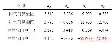
ʽ�У�rΪ�������ϸ��㵽�������ĵľ��������װ뾶֮�ȡ����У��������ϵ�����1��ʾ��
��1 �ǻ�����ֲ�������ϵ��
Table 1 Coefficients in distribution function of heated surface at cylinder head
��ʽ(3)��ʽ(4)��������Ϊ��3��߽��������ص��ǻ���������ڱ����ϣ������������ģ�Ͷ�ȼ��������¶ȳ�������⣬�Ӷ��������ڴ���ģ����ȼ���ұ����¶�֮�����ϵ�������߿���ͨ�����鷽�������õ���
Ϊ����֤��ֵ����������Ч�ԣ������������¶ȳ����в��ԡ��ڸǻ���������ڱڷֱ���������-�������ȵ�ż��ͼ1��ʾΪ�ǻ������ȵ�ż����ͼ��ͼ1(a)��ʾԲ��Ϊ�����ȵ�����Ϊ�����������¶Ȳ�����Ӱ�죬������ȵ�ż��ͷ��ǻ�����ľ���Ϊ1.0~1.5 mm����װ��ɺ�ʵ����ͼ1(b)��ʾ��
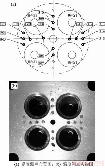
ͼ1 �ǻ������ȵ�ż����ͼ
Fig. 1 Thermocouples arrangements in cylinder cover
��ˣ�ȡ�������ͱ궨�����¸ǻ���������������������������жԱȣ�������ͬ�뾭�鹫ʽ�ļ��������������������������֤���ڴ��ȱ߽�ģ�ʹ�ͳ�뾭�鹫ʽ����ֵ���㷽���������ԡ�
2 ���ڴ���ģ�������Է���
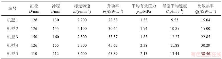
��5�ֵ��Ͳ��ͻ�ΪӦ�ö����������������и��ڴ��ȱ߽�ģ����Ч�Է�������ػ��͵IJ������2��ʾ�����У���ɢ����Ϊ��ƽ����������ȴҺɢ��������ͻ������ı�ֵ��
��ȼ��������¶ȳ��ļ����������������жԱȣ���ͼ2��ʾ��
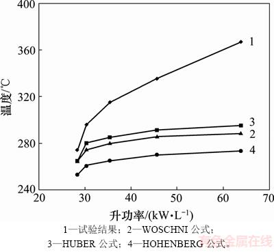
ͼ2 ��ͬ���Ͳ�ͬ�뾭�鹫ʽ�������Ա�
Fig. 2 Comparison of different semi-empirical formula in various engine types
��2 5�ֵ�����ȼ������Ҫ�������ܱ�
Table 2 Performance data of 5 types of diesel engines
������������WOSCHNI-HUBER��ʽ������������30 kW���ҵĵ����ܶȲ��ͻ�����Ӧ�ԽϺã������¶�������С��5%���������뾭�鹫ʽ����������ϸߡ�
3 ���ڴ��ȱ߽�ģ������
���������õ�����������ͼ3��ʾ�����ù����ģ�Ͷ�ȼ��������¶ȳ�������⡣���ȣ��ж��¶ȳ��ֲ��Ƿ�һ�£������ϴ����������ֲ�������ֱ�����߷ֲ�һ��Ϊֹ����Σ��жϷ�������������������Ƿ���������Χ֮�ڣ������ϴ�������뾭�鹫ʽ��ֱ��������������������Χ֮�ڣ��Ӷ��õ���Ч�İ뾭�鹫ʽ�ͱ���ֲ�������
����ͼ3��ʾ�������̣����з������������յõ����ϱ�������������͵��µİ뾭�鹫ʽ�����������ʽΪ

ʽ�У�CmΪ����ƽ���ٶȣ�m/s��p1��V1��T1�ֱ�ΪIVCʱ�̸��ڹ��ʵ�ѹ��(Pa)���ݻ�(m3)���¶�(K)��VsΪ�������ݻ���m3��p0Ϊ���Ϲ����¸���˲ʱѹ����Pa��c1Ϊ�����ٶ�ϵ����c2Ϊȼ������״ϵ����
��WOSCHNI��ʽ��ȣ���������İ뾭�鹫ʽ�����ѹ�����¶Ⱥ��ٶȵ�ָ��������������˲ʱ�ݻ���Ϊ�������ȣ���������������ת�ǵı仯����WOSCHNI��ʽ��HUBER��ʽ��HOHENBERG��ʽ�Լ���������¹�ʽ��GT-Power����õĸ���˲ʱ����ϵ��h���Ƴ����ߣ���ͼ4��ʾ����ͼ4��֪��������İ뾭�鹫ʽ����õ���h�ձ�ȴ�ͳ�뾭�鹫ʽ��h��ƫ�������20%���ϣ����߹����ܶȲ��ͻ����ڻ�����Զ���ڴ�ͳ��ȼ����������
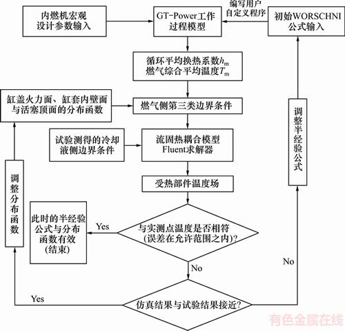
ͼ3 �����뾭�鹫ʽ������ͼ
Fig. 3 Block diagram of semi-empirical formula correction
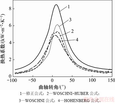
ͼ4 ��ͬ�뾭�鹫ʽh�������Ա�ͼ
Fig. 4 Contrastive diagram of h curves calculated by different semi-empirical formulas
4 ����������
4.1 �������������Ա�
�Ի���5�����������ϵ�4����������з�����㣬��ֵģ�Ͳ���Fluent����������⡣����500���������ڼ�������ʱ����������������������ȷ���ţ����յIJв����3��ʾ�����У� Ϊ�ܶȣ�k�ͦŷֱ�Ϊ�������������������������ܵĺ�ɢ�ʣ�Vx��Vy��Vz�ֱ�Ϊx��y��z��3�������ϵ��ٶȡ�
��3 �������в�
Table 3 Residual error of calculated results
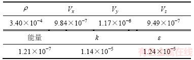
�ɱ�3��֪���������������������Ǻϣ����������Ϊ4.3%(����������϶�Ϊ��λ����)���������˵�����������õļ��㷽���ܹ��Ϻõ����㹤��Ӧ��Ҫ����Ϊȼ��������ṹ�Ż��ṩ�ο���
4.2 ���ģ���¶ȳ�����
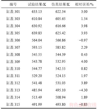
�Ա궨������(3 600 r/min��68 kW)����ֵ������Ϊ��������ϸ������������ͱ궨���ʵ�(3 200 r/min��62 kW)�������¶ȳ���������ͼ5��ʾ��
��4 �궨�����¸ǻ������¶���������������Ա�
Table 4 Comparison between calculation solution and test data under calibration condition in cylinder cover
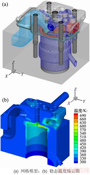
ͼ5 ��-����-��������ģ�ͼ���̬�¶ȳ���ͼ
Fig. 5 Mesh model and temperature yield of head, liner and body calculated at steady state
��ͼ5��֪�ǻ������ڱ����¶Ƚϸߣ��ʽ��䵥�����Ƴ�ͼ���ǻ������¶ȷֲ���ͼ��ͼ6��ʾ�������ֲ���ͼ��ͼ7��ʾ��
��ͼ6��ͼ7��֪���¶��������Ϊ�ǻ�������2��������֮��ı����������ֵΪ706 K�������ܶ����ֵΪ1 120 kW/m2���ڸǻ�����ѡȡ2��·�������Լ�ͷ����Ϊ������·�����¶ȷֲ���ͼ8��ʾ(ͼ��ɢ��Ϊ������)�������һ����֤����������������Խ��ʮ���Ǻϡ����⣬���߲������Ƚϴ����ǻ������¶ȷֲ��������ȡ���ͼ7Ҳ��֪�������ֲ��ܲ����ȣ����������ű�������������ߣ�����Ҫ�����ڸô���ȼ����ˢ��ǿ��ͬʱ��ȴҺ����Ҳ�ܸߡ�
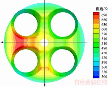
ͼ6 �ǻ������¶ȷֲ���ͼ
Fig. 6 Temperature distribution at heated surface of cylinder head
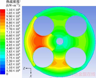
ͼ7 �ǻ���������ڱ���������ֲ���ͼ
Fig. 7 Heat flux distribution at heated surface of cylinder head
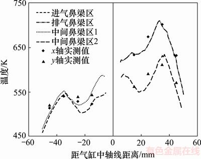
ͼ8 �ǻ�������·���¶ȷֲ�ͼ
Fig. 8 Temperature tested by thermocouple on heated surface of cylinder head along path
5 ����
1) ���������ܶȵ����ӣ�WOSCHNI��HOHENBERG�ȼ������˲ʱƽ����������ϵ���İ뾭�鹫ʽ�Ѿ��������ã���Щ�뾭�鹫ʽ�ļ�������ʵ�������ƫС15%~23%��
2) ������µļ������˲ʱƽ����������ϵ���İ뾭�鹫ʽ������������������ϼ����л���˽Ϻõ�Ӧ�ã�����������������С��5%���Ϻõ�����������ܶ���ȼ�������¶ȳ��ļ���Ҫ���Ҽ����ʱ���١�
3) ������������ȴҺ����¶Ƚϵͣ��ʷ������в�δ������ȴҺ���ڵ�������ȴҺ��ˮǻ�е�����²�ӽ�50 K����ȼ����ʵ�����й�������ȴҺ����¶�Ϊ360 K���ң���ˮǻ�кܿ��ܴ��ڷ��������Ӧͨ���Ż���Ʊ�����ڷ�����
�ο����ף�
[1] BORMAN G, NISHIWAKI K. Internal-combustion engine heat transfer[J]. Progress in Energy and Combustion Science, 1987, 13(1): 1-46.
[2] FAGUNDEZ J L S, SARI R L, MARTINS M E S, et al. Comparative analysis of different heat transfer correlations in a two-zone combustion model applied on a Si engine fueled with wet ethanol[J]. Applied Thermal Engineering, 2017, 115: 22-32.
[3] ANGELBERGER C, POINSOT T, DELHAY B. Improving near-wall combustion and wall heat transfer modeling in Si engine computations[J]. SAE Technical Papers, 1997, 22(1): 117-132.
[4] HAN Z, REITZ R D. A temperature wall function formulation for variable-density turbulent flows with application to engine convective heat transfer modeling[J]. International Journal of Heat and Mass Transfer, 1997, 40(3): 613-625.
[5] RAKOPOULOS C D, KOSMADAKIS G M, PARIOTIS E G. Critical evaluation of current heat transfer models used in CFD in-cylinder engine simulations and establishment of a comprehensive wall-function formulation[J]. Applied Energy, 2010, 87(5): 1612-1630.
[6] KOMNINOS N P, RAKOPOULOS C D. Heat transfer in HCCI phenomenological simulation models: a review[J]. Applied Energy, 2016, 181: 179-209.
[7] BERNI T, CICALESE G, FONTANESI S. A modified thermal wall function for the estimation of gas-to-wall heat fluxes in CFD in-cylinder simulations of high performance spark-ignition engines[J]. Applied Thermal Engineering, 2017, 115: 1045-1062.
[8] BROEKAERT S, DEMUYNCK J, DE CUYPER T, et al. Heat transfer in premixed spark ignition engines (part ��): identification of the factors influencing heat transfer[J]. Energy, 2016, 116: 380-391.
[9] DE CUYPER T, DEMUYNCK J, BROEKAERT S, et al. Heat transfer in premixed spark ignition engines (part ��): systematic analysis of the heat transfer phenomena[J]. Energy, 2016, 116: 851-860.
[10] MICHL J, NEUMANN J, ROTTENGRUBER H, et al. Derivation and validation of a heat transfer model in a hydrogen combustion engine[J]. Applied Thermal Engineering, 2016, 98: 502-512.
[11] SIDERI M, BERTON A, D��ORRICO F. Assessment of the wall heat transfer in 3D-CFD in-cylinder simulations of high performance diesel engines[J]. Energy Procedia, 2017, 126: 963-970.
[12] ������, ����, ֣��ƽ, ��. ���Ƿ��ں��ھֲ����ȵĸ�������ϴ��ȷ���[J]. ��ȼ������, 2017, 38(6): 139-144.
LIU Xiaori, LI Ming, ZHENG Qingping, et al. Fluid-solid interaction heat transfer analysis of cylinder head in consideration of boiling and in-cylinder local heat transfer[J]. Chinese Internal Combustion Engine Engineering, 2017, 38(6): 139-144.
[13] LI Yuanhong, KONG Songcharng. Coupling conjugate heat transfer with in-cylinder combustion modeling for engine simulation[J]. International Journal of Heat and Mass Transfer, 2011, 54(11): 2467-2478.
[14] SIDERI M, BERTON A, D��ORRICO F. Assessment of the wall heat transfer in 3D-CFD in-cylinder simulations of high performance diesel engines[J]. Energy Procedia, 2017, 126: 963-970.
[15] �ֽ���. ��ȼ������������ֵ����[M]. ����: ������ͨ��ѧ������, 1986: 50-56.
LIN Jielun. Numerical calculation of working process of internal combustion engine[M]. Xi��an: Xi��an Jiaotong University Press, 1986: 50-56.
(�༭ ����ΰ)
�ո����ڣ�2017-09-27�������ڣ�2017-11-05
������Ŀ(Foundation item)��������Ȼ��ѧ����������Ŀ(51605430)���㽭ʡ�������漼���о��ƻ���Ŀ(LGG18E060001)����������ᷢչ���������걨��Ŀ(20170533B21, 20180533B10)���㽭ʡ������ѧ�滮�о�����(2018SCG204)���㽭ʡ������������Ŀ(Y201635880, Y201737460) (Project(51605430) supported by the National Natural Science Foundation of China; Project(LGG18E060001) supported by the Basic Public Welfare Technology Research Plan of Zhejiang Province; Projects(20170533B21, 20180533B10) supported by the Self Declaration Project of Social Development Research in Hangzhou��Project(2018SCG204) supported by the Educational Science Planning Research Topic of Zhejiang Province��Projects(Y201635880, Y201737460) supported by the Scientific Research Projects of Education Department of Zhejiang Province)
ͨ�����ߣ����Ѻ꣬��ʿ����ʦ�����³����������������ֵ�����Լ����о���E-mail: fujh@zucc.edu.cn
ժҪ����Դ�ͳ�뾭�鹫ʽ�������ڸ߹����ܶ���ȼ�����ȱ߽���ص����⣬��WOSCHNI��ʽΪ����������������������ֵ���㷽������������ڸ������ܶ���ȼ�����ڴ��ȵİ뾭�鹫ʽ����ij�����������Ϊ����������-������ά��̬��Ϸ���ϵͳ������Fluent����������ֵ��⣬�����ý���������������������жԱȡ��о�����������ڸ߹����ܶ������������������ϣ�4�������·����������������������5%���ڡ���ˣ���������İ뾭�鹫ʽ�뽨�����������ģ���ܹ��Ϻõ�ģ����ȼ����̬���ȡ�
