
J. Cent. South Univ. (2017) 24: 609-624
DOI: 10.1007/s11771-017-3462-4

Distribution characteristics and impact on pump��s efficiency of hydro-mechanical losses of axial piston pump over wide operating ranges
XU Bing(���), Hu Min(����), ZHANG Jun-hui(�ž���), MAO Ze-bing(ë���)
State Key Laboratory of Fluid Power Transmission and Control, Zhejiang University, Hangzhou 310027, China
 Central South University Press and Springer-Verlag Berlin Heidelberg 2017
Abstract:
A novel performance model of losses of pump was presented, which allows an explicit insight into the losses of various friction pairs of pump. The aim is to clarify that to what extent the hydro-mechanical losses affect efficiency, and to further gain an insight into the variation and distribution characteristics of hydro-mechanical losses over wide operating ranges. A good agreement is found in the comparisons between simulation and experimental results. At rated speed, the hydro-mechanical losses take a proportion ranging from 87% to 89% and from 68% to 97%, respectively, of the total power losses of pump working under 5 MPa pressure conditions, and 13% of full displacement conditions. Furthermore, within the variation of speed ranging from 48% to 100% of rated speed, and pressure ranging from 14% to 100% of rated pressure, the main sources of hydro-mechanical losses change to slipper swash plate pair and valve plate cylinder pair at low displacement conditions, from the piston cylinder pair and slipper swash plate pair at full displacement conditions. Besides, the hydro-mechanical losses in ball guide retainer pair are found to be almost independent of pressure. The derived conclusions clarify the main orientations of efforts to improve the efficiency performance of pump, and the proposed model can service for the design of pump with higher efficiency performance.
Key words:
1 Introduction
Incessantly rising fuel costs and stringent pollution legislations are increasing the focus on efficiency in the mobile machine markets strongly, especially for swash plate type axial piston pumps, which makes the efficiency of axial piston pumps a major sales argument today in a majority of the mobile machine markets.
As it is well known, volumetric losses and hydro- mechanical losses are responsible for the decrease of efficiency of axial piston pumps. The volumetric losses are mainly resulted from the leakage flow losses via the lubricating gaps of pump and the compression flow losses due to the fluid compressibility. The hydro- mechanical losses involve the dry friction losses and viscous friction losses in various friction pairs of pump, mainly including piston cylinder pair, slipper swash plate pair, valve plate cylinder pair, ball guide retainer pair, piston head slipper socket pair and bearings. The performance models for volumetric losses can be found in many literatures. For instance, BERGADA et al [1] presented a complete set of the flow losses performance models. With the models, they demonstrated that the main source of the leakage in pump is either the slipper swash plate pair or the valve plate cylinder pair, producing over 94% of the total leakage.
However, few performance models relevant to a complete analysis of the hydro-mechanical losses in a pump over wide operating parameters can be found, which might be due to the complexity and multiformity, although there are previous studies relevant to the hydro-mechanical losses in certain individual friction pair of pump published as follows. MANRING [2], JEONG et al [3] and NILS et al [4] carefully analyzed the kinematics of piston in cylinder bore, and derived the formulas to estimate the instantaneous piston friction force as well as the average piston friction moment losses. KAZAMA [5] studied theoretically the lubrication characteristics of piston head slipper socket pair of pump, and carefully derived the basic equations to calculate the friction torque in the friction pair. Power losses in cylinder valve plate interface were investigated as a function of operating conditions in the form of leakage and viscous friction by JONATHAN [6]. WANG et al [7] measured the frictional torques in valve plate cylinder pair under the different conditions of oil film depth and speed of pump. CANBULUT et al [8] experimentally investigated the effect of surface roughness of slipper on the frictional power losses. LIN et al [9] proposed a tribo-dynamic model of slipper bearing in pumps, and presented the effects of cylinder speed, loading pressure and oil viscosity on the behavior of the slipper. SUN et al [10, 11] studied the algorithm and the influencing factors of the power losses in ball guide retainer pair. From the review of the previous researches, it can be seen that researches on hydro-mechanical losses in individual friction pair of pump have been long and deep. However, from the separate researches as what are presented above, it is difficult to establish an integrated evaluation: to what extent the hydro-mechanical losses of pump affect the efficiency, and how the hydro-mechanical losses in various friction pairs are distributed in a pump over wide operating parameters. A explicit and deeper insight into these problems might facilitate the work to improve the pump��s efficiency more directly and effectively.
First, a review of the existing performance models related to a complete analysis of the hydro-mechanical losses in pump is carried out. Since WILSON [12] firstly developed the steady-state flow rate and hydro- mechanical losses model for pumps, several researchers had tried to develop precise performance models for pumps. Existing models can be primarily grouped into two categories: empirical method and analytical method.
MIKESKA and et al [13] described an empirical method known as ��Polymod��. It is a polynomial based approach. The coefficients of the polynomials are calculated by a least squares fit to the flow and torque data. This approach requires a significant number of data points. The model is presented with independent variables such as pressure difference, speed and displacement ratio.
As for the analytical method, analytical models are presented based upon the physical nature of losses which are generally given by operating variables such as pressure difference and speed, often using coefficients to fit general behavior to a limited set of data [14-19].
Comparisons between the results derived from the existing models and the measurement data show a very good agreement. Nevertheless the considerable emphasis of the existing models is mainly placed on the unceasing refinement of the models, in order to enable the models which can predict general efficiency variation trends with better accuracy into the full operating area. However, from the models, it is impossible to separate power losses into their various components of pump. From this perspective, to some extent the models are not beneficial to users to assess the positions where the main losses are produced in pump.
This work aims to develop a performance model of losses of pump based on a novel method, which is capable of simulating the kinematics, dynamics and fluid characteristics, e.g., flow ripple and pressure ripple of pumps in great detail, especially allows an explicit insight into the losses in various friction pairs of pump. Based on the proposed performance model, the variation and distribution characteristics of hydro-mechanical losses in the various friction pairs of pump can be analyzed in detail over wide operating ranges. Simultaneously, the losses and efficiency of pump were experimentally measured over wide operating parameters.
2 Measurement of efficiency and losses
In order to determine the main influencing factor on pump��s efficiency over wide operating parameters, a test bed able to measure the efficiency and losses of pump was built. As a reference target of the following simulation, the pump with the displacement of 90 mL/r is chosen as the test pump. The rated pressure of the test pump is 35 MPa, and the rated speed is 2100 r/min. The test circuit and test bed are portrayed in Fig. 1.
The test pump is used in a closed circuit, and there is a charge pump in the main pump. In order to avoid the influence of the charge pump on the measurement of efficiency and losses of main pump, the charge pump was separated from the main pump. The variable displacement servo piston of main pump was fixed by the stopper bolt to control the displacement stably. The hydraulic oil in the circuit was exchanged by using an additional pump to control the oil temperature. A temperature sensor was mounted on the circuit to monitor the heat and temperature. Pressure sensors and pressure gages were mounted on the input port, output port and the leakage drain pipeline of the pump to monitor the pressure, where the flow sensors were mounted as well to monitor the flow rate. Speed sensor and torque sensor were mounted on the driving shaft of pump to test the input speed and torque of pump. The speed of pump was adjusted by the variable frequency motor with the variable-frequency drive. The load of the test pump was changed by adjusting the relief valve. The test data outputted by all the sensors with the standard signal were directly collected by the NI data acquisition card, and transferred to the computer with the help of data acquisition software. Based on the measurement data, the volumetric losses and hydro-mechanical losses of the test pump can be calculated through Eqs. (1) and (2). The overall efficiency, volumetric efficiency and mechanical efficiency can be calculated respectively through Eqs. (3)-(5).
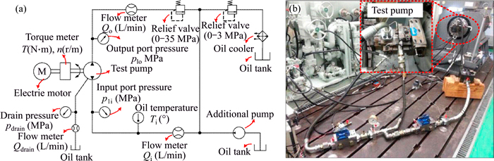
Fig. 1 Test circuit diagram (a) and test bed (b)
 (1)
(1)
 (2)
(2)
 (3)
(3)
 (4)
(4)
 (5)
(5)
As Fig. 2 portrays, the maximum overall efficiency of the test pump at the speed of 2100 r/min can reach 90%, however, with the decrease of displacement or pressure, the overall efficiency decreases considerably. The overall efficiency of pump drops to low efficiency area when it works under the conditions of low pressure or low displacement.

Fig. 2 Overall efficiency of test pump at 2100 r/min
Comparisons between the volumetric efficiency and mechanical efficiency of the test pump, as well as between the corresponding volumetric losses and hydro-mechanical losses of pump are made in Fig. 3, respectively corresponding to three typical cases of the working conditions: Case 1 corresponds to the conditions of rated speed, low pressure (5 MPa) together with the displacements ranging from 13% to 100% of full displacement; Case 2 corresponds to the conditions of rated speed, low displacement (13% of full displacement) together with the pressure differences ranging from near 0 to 35 MPa; Case 3 corresponds to the conditions of rated speed, rated pressure and full displacement.
As Fig. 3 presents, over wide operating parameters, the volumetric efficiency is generally higher than the mechanical efficiency. From another point of view, the hydro-mechanical losses of pump are generally greater than the volumetric losses, especially at the low pressure conditions and the low displacement conditions, in which cases the hydro-mechanical losses respectively take a great proportion ranging from 87% to 89% and from 68% to 97% of the total power losses of the pump. In order to further gain an explicit and deeper insight into the variation and distribution characteristics of hydro-mechanical losses in the various friction pairs of pump, a novel performance model of losses is developed based on computer co-simulation technology, due to the great difficulty in simultaneously measuring the hydro-mechanical losses in each individual friction pair of pump by experiment.
3 Simulation modeling
Axial piston pump is a complicated power unit related to mechanical, electrical and hydraulic elements. Therein, the dynamic behavior is the central attribute of pump. As an reference of the experiment, the performance model is constructed referring to the structure of the test pump in experiment, which employs a conical cylinder structure.
The hydro-mechanical losses are mainly affected by the following two influencing factors: the relative velocity and the interaction force between friction partners.
3.1 Kinematics analysis
The basic structure diagram of the pump with conical cylinder block is illustrated in Fig. 4. The cylinder bores are arranged on a conical surface with a cone angle �� in the cylinder block. The rotating cylinder block driven by shaft slides over the fixed valve plate at the speed of ��. The piston executes a linear movement in the cylinder bore. The piston head is connected with the slipper in the form of ball joint. The slipper sliding on the swash plate plane is in continuous contact with the swash plate under the action of retainer, which is forced by the ball guide under the action of compression springs between the cylinder and ball guide. The retainer rotates along the ball guide surface in the form of line contact.
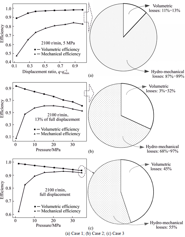
Fig. 3 Comparisons of efficiency and losses of pump:
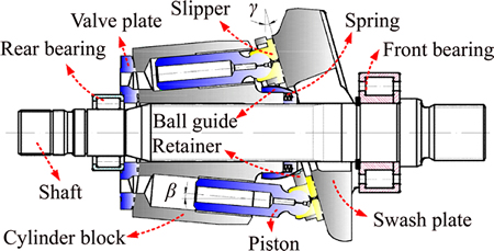
Fig. 4 Swash plate type axial piston pump
From the geometrical relationships of structural dimensions of pump, the piston stroke Sp can be described as a function of swash plate angle �� and cone angle �� as follows.
 (6)
(6)
The axial velocity and acceleration function of piston are derived as
 (7)
(7)
 (8)
(8)
As Fig. 5 portrays, the coordinate plane o''x''y'' via the ball centers of all the slipper sockets is parallel withthe swash plate plane. According to the equation of locus of piston head center (i.e. ball center of slipper socket), the angular position �� of the piston head center psl relative to the x''-axis and the distance of piston head center psl relative to point o'' can be derived, thus the velocity vs of ball center of slipper socket can be derived as Eq. (9) shows, which represents the velocity of slipper sliding on the swash plate plane.

 (9)
(9)
In Fig. 6, point p' is one of the contact points between ball guide and retainer, and point p is the reference point corresponding to point p'. The position vector of point p' in o-xyz coordinate system can be derived from the position vector of point p' in o'-x'y'z' coordinate system based on coordinate transformation method. Subsequently the relative motion locus between point p' and point p can be derived by the vector difference between the position vector op' and reference vector op as
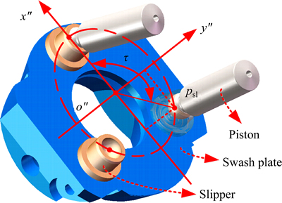
Fig. 5 Diagram of motion locus of slipper
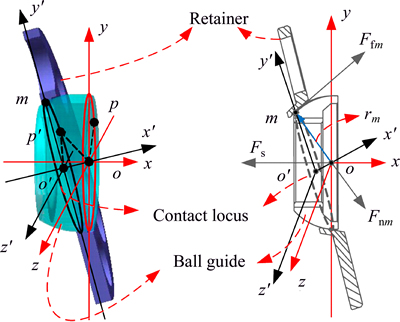
Fig. 6 Diagram of ball guide and retainer


 (10)
(10)
The relative velocity between point p' and point p, can be derived as


 (11)
(11)
Therein,
 (12)
(12)
3.2 Dynamics analysis
There are two types of force in pump, the pressure independent and pressure dependent force. The spring force Fs between cylinder and ball guide is a sort of pressure independent force. It is a function of spring stiffness k, pre-compressed length ��x0, and relative displacement drb between the cylinder and ball guide as follows.
 (13)
(13)
The force acting on the bottom of piston by hydraulic oil is a sort of pressure dependent force. In order to attain accurate interaction force between each part of pump, a co-simulation model is constructed as Fig. 7 shows.
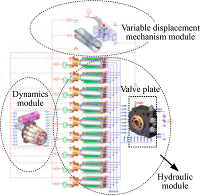
Fig. 7 Co-simulation model of pump
The hydraulic module supplies the real-time transient pressure force acting on the bottom of piston under different working conditions. The transient pressure of oil in piston chamber can be represented by
 (14)
(14)
Therein, the leakage flow in the clearance of piston cylinder interface is affected by the Poiseuille flow which is linked with the differential pressure and the Couette flow which is linked with the piston velocity as
 (15)
(15)
On basis of the clearance flow theory between two parallel disks, the leakage flow in the gap between slipper and swash plate can be derived as [20, 21]
 (16)
(16)
Analogously, the leakage flow in the gap between valve plate and cylinder can be derived as [20, 21]
 (17)
(17)
 (18)
(18)
The oil film depth between piston and cylinder, slipper and swash plate, as well as valve plate and cylinder are the key parameters to determine the volumetric losses of pump. The oil film in the former three lubrication interfaces generally presents a non- uniform depth field for the oil film depth field in the piston cylinder lubrication interface, as illustrated in Fig. 8. The angle axis in Fig. 8 stands for the angular position in circumferential direction around the piston. The length ratio axis in Fig. 8 stands for the contact length between piston and bush. The oil film depths in Eqs. (15)-(17) are assigned with the mean depth of the depth field. The mean depth of oil film in the clearance between piston and cylinder is approximately 15 ��m, mainly determined by the fit tolerance between piston and cylinder bore. The eccentricity of piston in the cylinder bore is predicted via a verified numerical model constructed by the author using the two dimensional Reynolds equation of lubrication. The detail can be seen in Ref. [22]. For the oil film in the valve plate cylinder interface, approximately mean depth of 8 ��m can be accepted [20]. In comparison with the oil film depth in piston cylinder interface and valve plate cylinder interface, the mean depth of the oil film in slipper swash plate interface undergoes a relatively larger variation with the changing working conditions, as portrayed in Fig. 9. With the increase of the displacement, the oil film depth of slipper swash plate pair gradually decreases. The oil film depth in slipper swash plate interface is predicted as well via a verified numerical model constructed by the author. The details can be seen in Ref. [23].
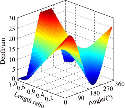
Fig. 8 Oil film depth field in piston cylinder lubrication interface
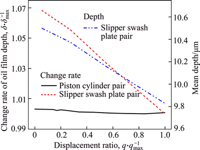
Fig. 9 Mean oil film depth in slipper swash plate lubrication interface versus displacement ratio and comparison of change rate of oil film depth between slipper swash plate interface and piston cylinder interface
The flow rate generated by the reciprocating motion of piston is determined by the piston velocity and the cross area of piston, as shown in Eq. (19). Expression for modelling the discharge/intake flow for the piston might be given by the classical orifice equation based on Bernoulli principle as [24, 25]
 (19)
(19)
 (20)
(20)
The variation of flow area Ar of dampening slot in valve plate is one of the key factors affecting the pressure of oil in piston chamber, especially in the transition region where the geometrical cross-sectional area of relief groove changes fast as depicted in Fig. 10. The variation of flow area, which is integrated in the
hydraulic module as valve plate model shown in Fig. 7, is described by a piecewise function divided into eight sections, and the flow area over one revolution of the cylinder bore is portrayed in Fig. 10.
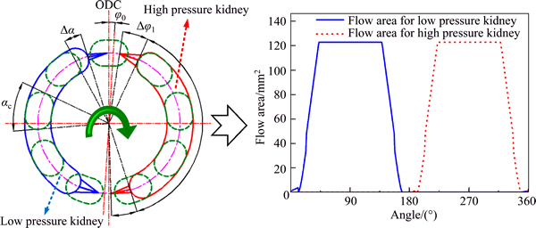
Fig. 10 Variation of flow area
Figure 11 illustrates the simulated transient pressure of oil in the piston chamber over one revolution. No pressure impact is observed in the pre-relieving pressure transition region at the pressure of 35 MPa, however a small pressure impact is produced in the pre-relieving pressure transition region at the pressure of 5 MPa. The reason is that, the pump is designed and optimized under the rated working condition. Therefore, at the 35 MPa rated pressure condition, the relief groove in valve plate has the capacity to eliminate the pressure impact, nevertheless at the low pressure of 5 MPa, the unchanged relief groove structure in valve plate cannot eliminate the pressure impact completely.
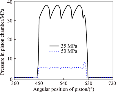
Fig. 11 Pressure in piston chamber
The spring force is set in the dynamics module based upon Eq. (13) via dynamically measuring the relative displacement between the ball guide and cylinder block of virtual digital pump. The relative motion relationship between each part of virtual digital pump is set as Fig. 12 shows in accordance with the realdynamics relationship.
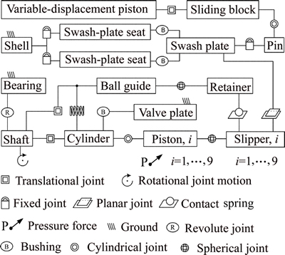
Fig. 12 Dynamics relationship between parts
Variable displacement mechanism module supplies the driving force for the variable displacement piston of pump in dynamics module to achieve different displacement conditions. In the dynamics module, the virtual digital pump is driven by the shaft at the speed of ��. In order to calculate the inertia force of parts and simulate the transmission of interaction force between each part, the mass and mass inertia tensor of each part are set in the dynamics module, in accordance with the attribute of the real part of pump.
3.3 Determination of friction coefficients
For axial piston pump, in case of most of operation conditions, the viscous friction and solid-state dry friction occur simultaneously in the friction pairs, represented by the mixed friction [20]. As one of the important influence factors on the hydro-mechanical losses of pump, the mixed friction coefficients of friction pairs of pump are hard-to-measure soft parameters under time-variant working conditions. Actually it might be impossible to be measured and attain the accurate friction coefficients of friction pairs of pump, due to the compact structure and the complex lubrication conditions, as well as the complex kinematics and dynamics of the parts. The widely adopted solution uses the least-squares technique to fit the friction coefficients. First, since the mixed friction coefficients are predominantly dependent upon the material and the lubricating conditions [20], a reasonable rough value of friction coefficients can be determined by analogue tribological experiments.
The analogue tribological experiments of the match of hardening steel paired with the brass material were carried out on a plate-plate tribological model by HOPPERMANN [26]. This match of frictional materials is widely used in the friction pairs of pump, for instance, in the piston cylinder pair, slipper swash plate pair, valve plate cylinder pair and piston head slipper socket pair. In the experiments by HOPPERMANN, the test specimens were immersed in an oil bath containing a standard mineral-based hydraulic fluid as the intermediate medium, which enables fluid lubrication. The measurement results demonstrate that the friction coefficients generally vary within a range of 0.008 to 0.03, depending upon the different working conditions. For the friction pairs in the pump, since the piston cannot be hydrostatically balanced as the slipper swash plate and valve plate cylinder interface, which can be designed as combined hydrostatic and hydrodynamic bearing [27], the lubrication conditions of slipper swash plate pair and valve plate cylinder pair generally surpass the lubrication condition of piston cylinder pair. Therefore, the initial friction coefficients of slipper swash plate pairs and valve plate cylinder pairs were respectively set to 0.008 and 0.01. The initial friction coefficients of piston cylinder pairs were set to 0.03, and the coefficients in piston head slipper socket pairs were set to 0.02 due to the form of ball friction coupling.
The analogue tribological experiments of the match of alloy steel paired with the alloy steel material which is applied in the ball guide retainer pair of pump, were carried out on a reciprocation tribo-tester by SUN [28]. Analogously, the test specimens were lubricated by the standard mineral-based hydraulic fluid. The test results demonstrate that the friction coefficients vary within a range of 0.112-0.141. Therefore, in the initial simulations the friction coefficients of ball guide retainer pairs were set to 0.12.
The friction coefficients of shaft bearings vary in a range of 0.0006-0.0012, which are given by the bearings maker. Therefore, the initial friction coefficients of bearings in the initial simulations are set to 0.001.
The initial simulations were carried out after the setup of the initial friction coefficients. In order to further improve the accuracy, the least-squares technique is used to tune the friction coefficients based upon the large number of measured experiment data points.
Since the total hydro-mechanical losses represent the sum of the losses in each friction pair of pump based on linear superposition principle, the least-squares analysis was carried out based on:

 (21)
(21)
where the variables L with the subscripts of notation of friction pairs correspond to the initial hydro-mechanical losses in the pair derived from the initial simulations. The variables f with the subscripts of notation of friction pairs stand for the coefficients to tune the corresponding initial friction coefficients. Pthm stands for the measured total hydro-mechanical losses of pump. Notice that the least-squares analysis based on Eq. (21) is independent upon the oil film depth of the lubricating interface discussed in the former section, due to that the viscous friction losses induced by the fluid film in the lubricating interface have been included in the mixed friction. The viscous friction losses induced by the variation of oil film depth with the changing working conditions can be reflected by the hydro-mechanical losses induced by the variation of mixed friction coefficients with the changing working conditions.
The 7 undetermined coefficients in Eq. (21) are solved under 7 pressure differences ranging from 5 to 35 MPa in increments of 5 MPa, at certain fixed speed and displacement conditions. The starting points of the least-squares analysis were set to the initial friction coefficients. The tuned friction coefficients at the speed of 2100 r/min are illustrated in Fig. 13.
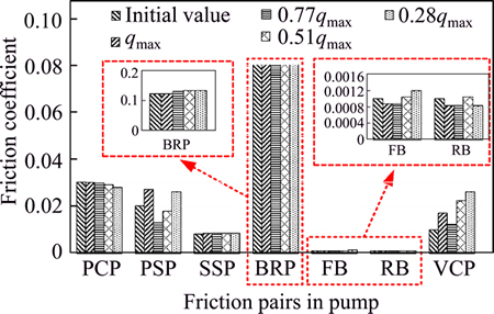
Fig. 13 Friction coefficients of various friction pairs of pump at speed of 2100 r/min under different displacement conditions
The tuned fiction coefficients in Fig. 13 are all within a reasonable range of variation, compared with the experimental results as discussed above. Finally the simulations are refreshed with the tuned coefficients.
3.4 Performance model of hydro-mechanical losses
Based upon the development of each module of pump, eventually the implemented co-simulation structure of performance model of hydro-mechanical losses in a pump is summarized in Fig. 14.
As portrayed in Fig. 14, the dynamics module transmits the kinematics parameters to the hydraulic module and variable displacement mechanism module in real time, including the displacement dvdp and the velocity vvdp of the variable displacement piston, as well as the velocity of each piston. The hydraulic module transmits the transient pressure force generated by the oil in each piston chamber and the driving force Fvd of variable displacement piston to the dynamics module in real time. Via the real-time data communication between dynamics module and hydraulic module, a fluid structure interaction [29] co-simulation model is established. All modules operate simultaneously in the co-simulation.
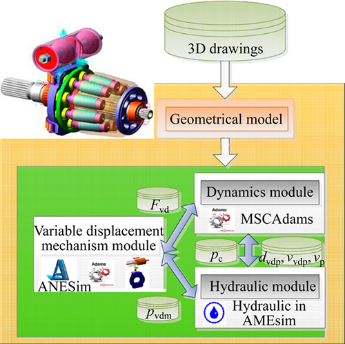
Fig. 14 Co-simulation structure
As the product of force and velocity, the hydro-mechanical losses in a friction pair of pump, can be derived from the simulated friction force and relative velocity between corresponding friction partners as
 (22)
(22)
4 Results and discussion
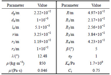
Simulation based researches are conducted for 100%, 77%, 51% and 28% of full displacement, with 4 groups of speeds, varying between 1000 and 2100 r/min, and 7 groups of pressure levels, from 5 to 35 MPa in increments of 5 MPa. The related simulation parameters are listed in Table 1.
4.1 Comparison between simulation and experiment
The relative motion locus between ball guide and retainer, which are respectively derived from Eq. (10) and simulation model, as well as the real wear patterns on the ball guide, are compared in Fig. 15.
Table 1 Parametric values
As Fig. 15 portrays, although there is small deviation between the equation result and simulation result at the initial position due to the instability in the start-up process of the dynamic simulation of pump, on the whole, the agreement between the dynamic simulation result and the equation result is very good. The real wear patterns on the ball guide shown in Fig. 15 are resulted from the relative motion between ball guide and retainer. The comparison shows good correlation between the theoretical expectations and the actual pattern of the relative motion locus between ball guide and retainer.

Fig. 15 Relative motion locus between ball guide and retainer at swash plate angle of 16.2��:
Comparisons with the experimental data points of hydro-mechanical losses of pump are shown in Fig. 16, versus the pressure differences ranging from 5 to 35 MPa in increments of 5 MPa, with respect to the pump speed ranging from 1000 to 2100 r/min, and the pump displacement ranging from 28% to 100% of full displacement.
Figure 16 illustrates that the simulation results agree well with the experimental results in a wide operating range. However, the simulation results present a linear variation trend on the whole versus the pressure difference, and some relatively larger deviations can be found in the comparisons between simulation and test points. The deviations are primarily caused by the inevitable errors in the determination of friction coefficients, due to the great difficulty in the determination of accurate friction coefficients corresponding to each transient operating conditions. However, on the whole, the available accuracy is adequate to analyze and discuss the general distribution characteristics of hydro-mechanical losses in the various friction pairs of pump over wide operating ranges.
4.2 Distribution characteristics of hydro-mechanical losses in various friction pairs of pump under full displacement conditions
The distribution proportion of hydro-mechanical losses in the various friction pairs of pump with respect to different pressure levels under full displacement conditions is portrayed in Fig. 17, respectively at the speed of 2100, 1700, 1300 and 1000 r/min.
As portrayed in Fig. 17, under the conditions of full displacement and different pressure levels, varying from the rated pressure to 14% of the rated pressure, the main hydro-mechanical losses in the pump derive from the piston cylinder pair, slipper swash plate pair and valve plate cylinder pair, of which the occupied proportion respectively vary in the range of 21.35%-58.96%, 28.97%-53.25% and 5.97%-23.25%. Besides, the results also indicate that the main sources of the hydro-mechanical losses in the pump hold changeless with the variation of pressure levels. The uppermost source of hydro-mechanical losses of pump at full displacement generally is either piston cylinder pair or slipper swash plate pair.
Special variation trend of hydro-mechanical losses with pressure is found in the ball guide retainer pair, as Fig. 18 shows, which depicts that the hydro-mechanical losses in ball guide retainer pair are almost independent of the pressure levels, different from the hydro- mechanical losses in other friction pairs which are proportional to the pressure levels.
There are mainly two influence factors responsible for the hydro-mechanical losses in the ball guide retainer pair, the friction force and the relative velocity between ball guide and retainer. First, due to the ball guide and retainer are fully immersed in the hydraulic fluid in the case of pump under each conditions, as well as due to the packing force Fnm between ball guide and retainer is mainly determined by the spring force, which is generally not too big (1080 N in the test pump) and almost holds constant (described in the following Eq. (23) and Eq. (24)), the friction coefficients of ball guide retainer pair vary in a small range with the change of pressure levels. Therefore, the friction force generated in the ball guide retainer pair is almost independent of the pressure levels.
The interaction force acting on certain contact point m between ball guide and retainer is depicted in Fig. 6, including tangential friction force Ffm and normal force Fnm. The contact locus (as Fig. 6 portrays) between ball guide and retainer can be assumed to be divided into nz discrete points. In direction of x axis (denoted by i), the resultant force of interaction force acting on each discrete contact point is equal to spring force as
 (23)
(23)
 (24)
(24)
The direction of normal force and friction force acting on certain discrete contact point m respectively corresponds to the opposite direction of the radius vector rm (portrayed in Fig. 6) and the relative velocity between the contact point and the corresponding reference point. Based on this relationship, the interaction force acting on each discrete contact point can be derived from Eqs. (10)-(13), Eqs. (23) and (24). Subsequently, the hydro-mechanical losses in ball guide retainer pair can be derived as
 (25)
(25)
The relative velocity ��Vm in Eq. (25) is described by Eq. (11), which presents that the relative velocity is independent of pressure. Therefore, it finally gives rise to the independence of hydro-mechanical losses generated in ball guide retainer pair from the pressure. Figure 19 illustrates the comparisons of hydro-mechanical losses generated in the ball guide retainer pair, respectively derived from the dynamic simulation and the conventional equation, at the full displacement conditions.
In Fig. 19, relatively significant deviations can be found in the case of 2100 r/min. This is mainly caused by the greater vibration of pump parts when the virtual digital pump runs in the dynamic simulation at high speed than low speed. Figrue 19 further illustrates the independence of hydro-mechanical losses in ball guide retainer pair from the variation of pressure. This phenomenon is also observed by SUN��s calculation and test results [29]. Due to this phenomenon, the distribution proportion of hydro-mechanical losses in the ball guide retainer pair might reach a high value under the low pressure, high speed and full displacement conditions. As shown in Fig. 17(a), the hydro-mechanical losses in the ball guide retainer pair occupy a proportion of up to nearly 10% of the total hydro-mechanical losses of pump, under the conditions of 14% of the rated pressure of pump.
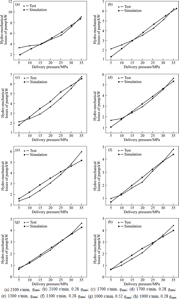
Fig. 16 Comparisons between experimental results and simulation results under different working conditions of pump:
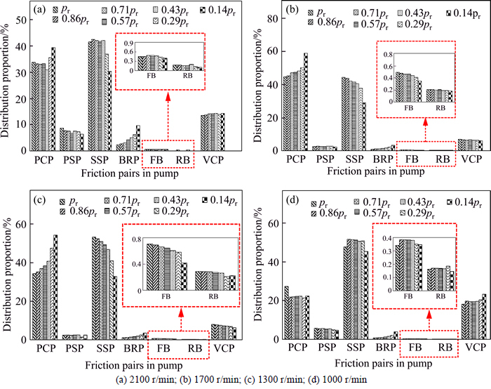
Fig. 17 Distribution proportion of hydro-mechanical losses in various friction pairs of pump at full displacement conditions:
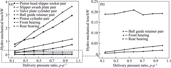
Fig. 18 Hydro-mechanical losses of various friction pairs of pump versus pressure levels
4.3 Distribution characteristics of hydro-mechanical losses in various friction pairs of pump working in low-efficiency operation area
As discussed in Fig. 2, the low-efficiency operation area of pump includes the low pressure working conditions and low displacement working conditions. In the case of low pressure and fixed speed working conditions, the distribution proportion of hydro- mechanical losses in the various friction pairs of pump with respect to different displacements is portrayed in Fig. 20.
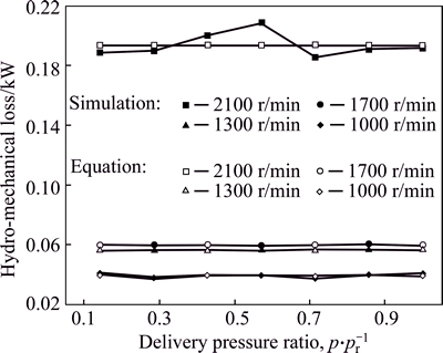
Fig. 19 Comparisons of hydro-mechanical losses generated in ball guide retainer pair respectively derived from dynamic simulation and conventional equation
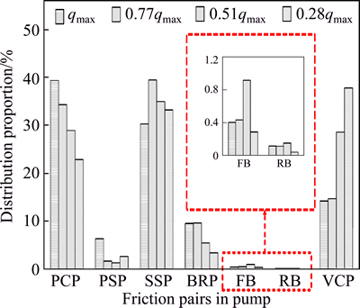
Fig. 20 Distribution proportion of hydro-mechanical losses in various friction pairs of pump under conditions of 2100 r/min and 5 MPa
As portrayed in Fig. 20, the proportion occupied by the hydro-mechanical losses generated in the piston cylinder pairs greatly decreases with the decrease of displacement, on the contrary, the proportion occupied by the hydro-mechanical losses generated in the slipper swash plate pairs and valve plate cylinder pairs gradually increases. That means, the main sources of hydro- mechanical losses of pump generally change to slipper swash plate pair and valve plate cylinder pair at low displacement conditions from piston cylinder pair and slipper swash plate pair at full displacement conditions, as illustrated in Figs. 21 and 22. The main reasons for this result are primarily the decrease of piston stroke and piston velocity with decreasing displacement, which are straightforward to understand from Eqs. (6) and (7).
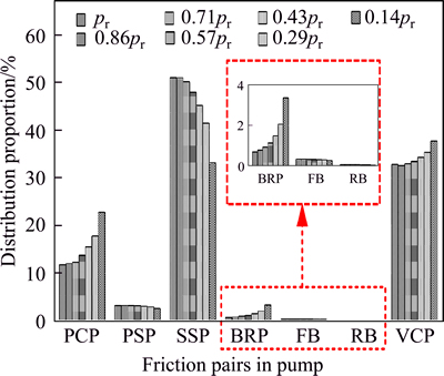
Fig. 21 Distribution proportion of hydro-mechanical losses in various friction pairs of pump under conditions of 2100 r/min and 28% of full displacement
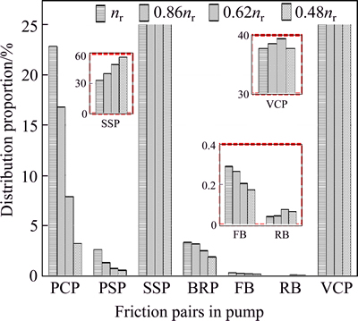
Fig. 22 Distribution proportion of hydro-mechanical losses in various friction pairs of pump under conditions of 5 MPa and 28% of full displacement
5 Conclusions
A novel performance model to calculate the losses of axial piston pump is presented in this work, which is capable of simulating the kinematics, dynamics and fluid characteristics. Compared with the previous models, the model in this work allows an explicit insight into the characteristics of power losses in various friction pairs of pump.
By the proposed model and the experiments, the distribution characteristics and impact on the pump��s efficiency of hydro-mechanical losses are studied over wide operating ranges. A good agreement is found in the comparisons between the simulation and experimental results over wide operating ranges. On the basis of the results, the following conclusions can be derived.
1) The hydro-mechanical losses take a great proportion ranging from 87% to 89% and from 68% to 97%, respectively, of the total power losses of the test pump working under 5 MPa pressure conditions within a large variation range of displacement, and 13% of full displacement conditions within a large variation range of pressure, corresponding to the low-efficiency areas of pump. That means the hydro-mechanical losses are the main factor affecting the efficiency of pump.
2) The load pressure levels of pump have little effect on the hydro-mechanical losses of ball guide retainer pair. Therefore, under the conditions of low pressure, high speed and full displacement, the distribution proportion occupied by the hydro- mechanical losses of ball guide retainer pair might reach a relatively higher value.
3) The uppermost source of hydro-mechanical losses of pump is either piston cylinder pair or slipper swash plate pair under full displacement conditions, with arbitrary speed varying within a range from 48% to 100% of rated speed, or pressure levels varying within a range from 14% to 100% of rated pressure. The distribution characteristic of hydro-mechanical losses in the various friction pairs of pump is sensitive to the displacement of pump. At the low displacement working conditions, together with arbitrary speed varying within a range from 48% to 100% of rated speed, or pressure levels varying within a range from 14% to 100% of rated pressure, the main sources of hydro-mechanical losses of pump change to slipper swash plate pair and valve plate cylinder pair.
Acknowledgments
The authors sincerely thank senior researcher Akira Nakayama and Shohei Ryu of Technical Research Center of Hitachi Construction Machinery Co., Ltd. of Japan for the constructive discussion and the experimental assistance.
Nomenclature
Ar
Flow area of dampening slot
Ap
Cross area of piston
Cr
Flow coefficient
drb
Displacement between cylinder and ball guide
dp
Diameter of piston
do
Diameter of the orifice opening in piston
lo
Length of the orifice opening in piston
fbr
Friction coefficient of ball guide retainer pair
Ff
Friction force
Ffm
Tangential friction force acting on contact point m between ball guide and retainer
Fvd
Driving force
Fnm
Normal force acting on contact point m between ball guide and retainer
Fs
Spring force
k
Spring stiffness
Ke
Elastic modulus of hydraulic oil
lp
Gap length between piston and bush
n
Working speed of pump
nr
Rated speed of pump
p, pr
Delivery pressure, rated pressure
Pbr
Hydro-mechanical losses in ball guide retainer pair
pc
Transient pressure in piston chamber
pl
Pressure of oil in slot of valve plate
pli
Input port pressure of pump
plo
Output port pressure of pump
p0
Pressure of oil in the case of pump
Pvtp
Volumetric losses of the test pump
Pmtp
Hydro-mechanical losses of the test pump
q
Displacement of pump
qr
Flow rate yielded by the motion of piston
qi
Reverse flow flowing through the dampening slot in valve plate
qmax
Full displacement of pump
qlp
Leakage of piston cylinder pair
qls
Leakage of slipper swash-plate pair
qlv
Leakage of valve-plate cylinder pair
Qdrain
Leakage of pump
Qi
Input flow rate of pump
Qo
Output flow rate of pump
r
Radius of ball guide
rm
Radius vector of contact point m
r1, r2
Structure parameters of slipper
R
Distance from IDC to center line of shaft
R1, R2,
R3, R4
Structure parameters of valve plate
T
Input torque of the test pump
Tp
Pump torque
Vc
Volume of oil in piston chamber
V0
Volume of oil in piston chamber at ODC
z
Number of friction partners
��, ��
Coefficients for each pump
��
Cone angle of cylinder block
��
Angular position of piston relative to ODC
��
Cone angle of retainer
��
Angular position of contact point relative to reference point in o'-x'y'z' coordinate system
��x0
Pre-compressed length of spring
��
Swash plate angle
��
Angular position of the piston head center relative to the x''-axis
��ov, ��v,
��m
Overall efficiency, volumetric efficiency and mechanical efficiency of the test pump
��v
Relative velocity between retainer and ball guide
��
Density of oil
��p
Oil film depth of piston cylinder pair
��s
Oil film depth of slipper swash-plate pair
��v
Oil film depth of valve-plate cylinder pair
��
Viscosity of oil
��p
Eccentricity of piston in cylinder bore
��f
Coefficient determined by the structure of valve plate
v
Relative velocity
Whm
Hydro-mechanical losses
PCP
Piston cylinder pair
VCP
Valve-plate cylinder pair
SSP
Swash-plate slipper pair
PSP
Piston-head slipper-socket pair
BRP
Ball-guide retainer pair
FB
Front bearing
RB
Rear bearing
References
[1] BERGADA J M, KUMAR S, DAVIES D L. A complete analysis of axial piston pump leakage and output flow ripples [J]. Applied Mathematical Modelling, 2012, 36(4): 1731-1751.
[2] MANRING N D. Friction forces within the cylinder bores of swash plate type axial piston pumps and motors [J]. ASME Journal of Dynamic Systems, Measurement and Control, 1999, 121(1): 531-537.
[3] JEONG H S, KIM H E. On the instantaneous and average piston friction of swash plate type hydraulic axial piston machines [J]. Journal of Mechanical Science and Technology, 2004, 18(10): 1700-1711.
[4] NILS V, HUBERTUS M, ULRICH B, DAVID B. Mechanical losses in the piston-bushing contact of axial piston units [C]// Proceedings of the 9th JFPS International Symposium on Fluid Power. Matsue: The Japan Fluid Power System Society (JFPS), 2014: 368-375.
[5] KAZAMA T. Mixed lubrication simulation of hydrostatic spherical bearings for hydraulic piston pumps and motors [J]. Journal of Advanced Mechanical Design Systems and Manufacturing, 2008, 2(1): 71-82.
[6] JONATHAN E B. Power losses in the lubricating gap between cylinder block and valve plate of swash plate type axial piston machines [D]. West Lafayette, USA: Purdue University, 2008.
[7] WANG Bin, ZHOU Hua, YANG Hua-yong. Experimental study of frictional torque properties of plane port pairs in axial piston pump [J]. Journal of Zhejiang University (Engineering Science), 2009, 43(11): 2091-2095. (in Chinese)
[8] CANBULUT F, SINANOGLU C, KOC E. Experimental analysis of frictional power loss of hydrostatic slipper bearings [J]. Industrial lubrication and Tribology, 2009, 61(3): 123-131.
[9] LIN Shuo, HU Ji-bin. Tribo-dynamic model of slipper bearings [J]. Applied Mathematical Modelling, 2015, 39(2): 548-558.
[10] SUN Yi, JIANG Ji-Hai, LIU Jun-long. Relative position and friction power loss between slipper retainer and ball guide in axial piston pump [J]. Journal of South China University of Technology, 2011, 39(4): 82-87. (in Chinese)
[11] SUN Yi, LI Yang, JIANG Ji-hai. Stress analysis and experiments for slipper retainer and ball guide in axial piston pump [J]. Journal of Xi��an Jiaotong University, 2013, 47(2): 103-108. (in Chinese)
[12] WILSON W E. Performance criteria for positive displacement pumps and fluid motors [C]// ASME Semi-annual meeting. Chicago, USA: ASME, 1948: 14-48.
[13] MIKESKA D, IVANTYSYNOVA M. A precise steady state model of displacement machines for the application in virtual prototyping of power split drives [C]// 2nd FPNI-PhD Symposium. Modena, Italy Center for Compact and Efficient Fluid Power, 2002: 95-111.
[14] PACEY D A, TURNQUIST R O, CLARK S J. The development of a coefficient model for hydrostatic transmissions [C]// Proceedings of the 35th national conference on fluid power. Chicago: IIIinois Institute of Technology, 1979: 173-178.
[15] ZAROTTI G L. Pump efficiencies approximation and modeling [C]// 6th BHRA Fluid Power Symposium. Cambridge, England BHRA Fluid Engineering, 1981: 145-164.
[16] MCCANDLISH D, DOREY R E. The mathematical modeling of hydrostatic pumps and motors [J]. Proceedings of the Institution of Mechanical Engineers, Part B: Journal of Engineering Manufacture, 1984, 198(1): 165-174.
[17] DOREY R E. Modeling of losses in pumps and motors [C]// Proceedings of the First Bath International Fluid Workshop. England: Research Studies Press, 1988: 71-97.
[18] GRANDALL D R. The performance and efficiency of hydraulic pumps and motors [D]. Twin Cities, USA: University of Minnesota, 2010.
[19] RYDBERG K E. Efficiencies for variable hydraulic pumps and motors��Mathematical models and operation conditions [C]// IEI/Flu- MeS. Linkoping, Sweden: Link ping University, 2009: 1-37.
[20] IVANTYSYN J, IVANTYSYNOVA M. Hydrostatic pumps and motors [M]. New Delhi: Academic Books International, 2001.
[21] GUAN Chang-bin, JIAO Zong-xia, HE Shou-zhan. Theoretical study of flow ripple for an aviation axial piston pump with damping holes in the valve plate [J]. Chinese Journal of Aeronautics, 2014, 27(1): 169-181.
[22] XU Bing, ZHANG Jun-hui, YANG Hua-yong, ZHANG Bin. Investigation on the radial micro-motion about piston of axial piston pump [J]. Chinese Journal of Mechanical Engineering, 2011, 26(2): 325-333.
[23] XU Bing, ZHANG Jun-hui, YANG Hua-yong. Investigation on structural optimization of anti-overturning slipper of axial piston pump [J]. Sci China Tech Sci, 2012, 55(8): 1-9.
[24] HUANG Jia-hai, QUAN Long, ZHANG Xiao-gang. Development of a dual-acting axial piston pump for displacement-controlled system [J]. Proc Inst Mech Eng, Part B: J Eng Manuf, 2014, 228(4): 606-616.
[25] XU Bing, HU Min, ZHANG Jun-hui. Impact of typical steady-state conditions and transient conditions on flow ripple and its test accuracy for axial piston pump [J]. Chinese Journal of Mechanical Engineering, 2015, 28(5):1012-1022.
[26] HOPPERMANN A. Laser structured contact surfaces��Effects on the tribological behaviour of hydraulic material combinations [J]. lhydraulik und Pneumatik, 2004, 48(1): 1-13.
[27] IVANTYSYNOVA M. The piston cylinder assembly in piston machines��A long journey of discovery [C]// Proceedings of 8th IFK International Conference on Fluid Power. Dresden, Germany:  POGONI, 2012: 307-332.
[28] SUN Yi. Research on lubrication and power loss of slipper and its matching parts within axial piston pump [D]. Xi��an, China: Harbin Institute of Technology, 2013. (in Chinese)
[29] CHEN Qi-Ping, SHU Hong-yu, FANG Wen-qiang, HE Lian-ge, YANG Mao-ju. Fluid structure interaction for circulation valve of hydraulic shock absorber [J]. Journal of Central South University, 2013, 20(3): 648-654.
(Edited by FANG Jing-hua)
Cite this article as:
XU Bing, Hu Min, ZHANG Jun-hui, MAO Ze-bing. Distribution characteristics and impact on pump��s efficiency of hydro-mechanical losses of axial piston pump over wide operating ranges [J]. Journal of Central South University, 2017, 24(3): 609-624.
DOI:https://dx.doi.org/10.1007/s11771-017-3462-4Foundation item: Project(2014CB046403) supported by the National Basic Research Program of China; Project(2013BAF07B01) supported by the National Key Technology R&D Program of China
Received date: 2015-05-26; Accepted date: 2016-12-30
Corresponding author: XU Bing, Professor, PhD; Tel: +86-15157158489; E-mail: bxu@zju.edu.cn
Abstract: A novel performance model of losses of pump was presented, which allows an explicit insight into the losses of various friction pairs of pump. The aim is to clarify that to what extent the hydro-mechanical losses affect efficiency, and to further gain an insight into the variation and distribution characteristics of hydro-mechanical losses over wide operating ranges. A good agreement is found in the comparisons between simulation and experimental results. At rated speed, the hydro-mechanical losses take a proportion ranging from 87% to 89% and from 68% to 97%, respectively, of the total power losses of pump working under 5 MPa pressure conditions, and 13% of full displacement conditions. Furthermore, within the variation of speed ranging from 48% to 100% of rated speed, and pressure ranging from 14% to 100% of rated pressure, the main sources of hydro-mechanical losses change to slipper swash plate pair and valve plate cylinder pair at low displacement conditions, from the piston cylinder pair and slipper swash plate pair at full displacement conditions. Besides, the hydro-mechanical losses in ball guide retainer pair are found to be almost independent of pressure. The derived conclusions clarify the main orientations of efforts to improve the efficiency performance of pump, and the proposed model can service for the design of pump with higher efficiency performance.
