

![]()
Trans. Nonferrous Met. Soc. China 22(2012) 1336-1341
Microstructure and mechanical properties of AZ31B magnesium alloy gas metal arc weld
DONG Hong-gang1, 2, LIAO Chuan-qing2, YANG Li-qun2
1. State Key Laboratory of Advanced Welding and Joining, Harbin Institute of Technology, Harbin 150001, China;
2. School of Materials Science and Engineering, Dalian University of Technology, Dalian 116085, China
Received 25 May 2011; accepted 22 August 2011
Abstract:
Wrought magnesium alloy sheets were butt welded with gas metal arc welding process. Pores in the weld were investigated under different welding parameters, the causes of pore formation were systematically disposed, and the effects of porosity on the microstructure and mechanical properties of the joint were analyzed. The microstructure examination shows that the pores mainly appear close to the top or bottom part of the weld, and could connect to each other and lead to the formation of cracks in the welds. However, the pores can be controlled with proper welding parameters. The tensile testing results reveal that the average joint strength is close to or higher than that of the base metal. The microhardness in the weld can be even higher than that in the base metal due to the second phase strengthening of ��-Mg17(Al, Zn)12 formed in the weld.
Key words:
Mg alloy; gas metal arc welding; porosity; microstructure; second phase strengthening;
1 Introduction
Magnesium and magnesium alloys have low density, high specific strength and stiffness, high damping capacity, good cast ability and good electromagnetic interfere shielding capacity [1,2]. Therefore, magnesium alloys are considered one of the most potential engineering materials in the twenty-first century to replace steel and aluminum alloys in many structures [3,4].
At present, fusion welding processes, such as gas metal arc welding [5], laser welding [6] and gas tungsten arc welding [7], have been widely investigated to join magnesium alloys; however, it is still a challenge to achieve solid magnesium alloy welds with fusion welding processes because defects such as pores, cracks and slag inclusions often occur in the resultant weld. Especially, pores are often found in the weld during fusion welding of magnesium alloy. ZHAO and DEBROY [8] conducted laser welding of AM60B casting magnesium alloy and suggested that the porosity in the weld could be increased by the coalescence of pores, which already existed in the base metal before welding, and the increase of pore radius caused by the decrease of surface tension pressure. LIU et al [9] studied the pore formation during hybrid laser-tungsten inert gas welding of AZ31B magnesium alloy and found the inert gas protection of laser beam could be effectively improved by appending lateral shielding gas for laser beam and the amount of pores could be significantly reduced. WU et al [10] investigated the effects of hydrogen levels on the porosity and mechanical properties of AZ91 magnesium alloy castings and proposed that the microporosity increased with the increase of hydrogen content. Meanwhile, the tensile strength of the joint decreased with the increase of hydrogen level. Moreover, HAFERKAMP et al [11] considered that the presence of gas inclusions in the base metal could result in the formation of large pores in the weld during laser welding of magnesium alloys.
However, the literatures on the gas metal arc welding of magnesium alloys are limited, especially the distribution of pores in the consequent weld. In this study, the microstructure and mechanical properties of the magnesium alloy joints made with gas metal arc welding were studied, and the effect of porosity on the mechanical properties of the resultant joint was systematically investigated.
2 Experimental
The wrought AZ31B magnesium alloy sheets with dimensions of 200 mm��80 mm��1.6 mm were gas metal arc welded with AZ61A magnesium alloy wire with diameter of 1.6 mm. Butt joints were made on a backing plate with 8 mm wide and 1 mm-deep groove for the bead formation control on the backside of the weld. The nominal compositions of the base metal and filler wire are listed in Table 1. Before welding, the work piece was cleaned with acetone to remove grease or oil and brushed with a stainless steel brush to remove oxide films from the faying surfaces.
Table 1 Nominal compositions of AZ31B and AZ61A magnesium alloys (mass fraction, %)
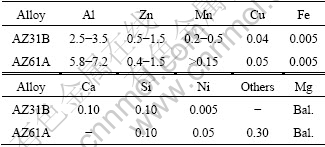
During welding, argon was used as the shielding gas at a flow rate of 15 L/min. The droplet transfer mode was spray transfer, the contact tip to work distance was 15 mm and the welding voltage was 26.5 V. The welding current was coupled with the wire feeding speed as the welding source was designed, and the wire feeding speed and travel speed are listed in Table 2. After welding, the specimens were transversely cut from the joints, mounted and polished for microstructural examination by an optical microscope. The distribution of the alloying elements was measured with electron probe microanalysis (EPMA), and the microhardness test was conducted along the cross-section of the weld. Three samples from each joint were prepared for tensile test and the dimensions of the samples are shown in Fig. 1. The tensile strength of the AZ31B magnesium alloy base metal was measured to be 278 MPa on average.
Table 2 Welding parameters during gas metal arc welding of AZ31B magnesium alloy
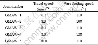
Fig. 1 Dimensions of sample for tensile testing
3 Results and discussion
3.1 Microstructure
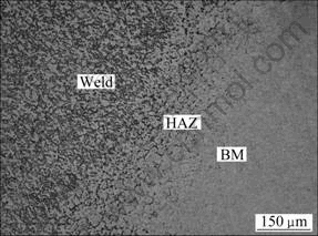
The typical microstructure of the weld from joint GMAW-3 is shown in Fig. 2. The base metal (BM), weld and heat-affected zone (HAZ) could be obviously distinguished from each other, and the fusion boundary is clear. It can be seen that the grains are coarser in the heat-affected zone than those in the weld and base metal.
![]()
![]()
![]()
![]()
![]()
![]()
![]()
![]()
![]()
![]()
![]()
![]() Fig. 2 SEM image of weld from joint GMAW-3 at travel speed of 8.3 mm/s and wire feeding speed of 110 mm/s
Fig. 2 SEM image of weld from joint GMAW-3 at travel speed of 8.3 mm/s and wire feeding speed of 110 mm/s
The backscattered electron image taken in the weld from joint GMAW-1 is shown in Fig. 3, and a pore with diameter of around 350 ��m appears in the center of the image. The contents of major elements at three typical spots were examined by EPMA. The scanning results at spots A, B and C and the calculated phases are listed in Table 3. The measurement shows that the contents of Mg, Zn and Al at the gray matrix (spot A) are 98.635%, 0.295% and 1.070%, respectively, and the contents of Al and Zn at the bright area (spot B) are 7.605% and 7.685%, respectively, which are much higher than those at spot A. Spot C is located within the inner wall of the pore and a high percent of nitrogen is detected. It can be seen from Table 3 that the nitrogen content at spot C is as high as 21.151% and this high amount of nitrogen could easily react with magnesium at elevated temperatures to form nitride, such as Mg3N2 [9]. Based on the above measurement, it can be postulated that the microstructure in the weld consists of? ��-Mg17(Al, Zn)12 phases uniformly dispersing in the ��-Mg matrix, and the similar microstructure was also reported by XU et al [12].
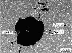
Fig. 3 Backscattered electron image of weld from joint GMAW-1
Table 3 EPMA elemental scanning analysis result of weld in Fig. 3 (mass fraction, %).
3.2 Distribution of pores in weld
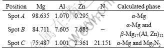
The microstructures in the magnesium alloy welds made with gas metal arc welding process under different welding parameters are shown in Fig.4. It can be seen that irregular pores with diameter ranging from 50- 350 ��m mainly appear close to the top or bottom part of the welds. Meanwhile, pores in the weld could connect to each other and form bigger pores, or even yield cracks due to the existence of thermal stress in the joints as shown in Figs. 4(a) and (c).
As discussed above, nitrogen is detected in the inner wall of a pore indicating that the air, which accidentally entered the weld pool during welding, could be trapped in and form pores if the air could not escape from the weld pool upon solidification. This phenomenon was also reported by LIU et al [9] while conducting hybrid laser-tungsten inert gas arc welding of magnesium alloy AZ31B. Meanwhile, pores in the magnesium weld could come from bubbles resulted from the moisture and/or evaporation of those elements (such as Mg and Zn) with low melting point and high vapor pressure existing in the magnesium alloy base metal [13].
Fig. 4 SEM images of welds from joints: (a) GMAW-2; (b) GMAW-5 on top surface; (c) GMAW-5 on bottom surface; (d) GMAW-3; (e) GMAW-4
Due to the low density of magnesium, the buoyancy is too small for the bubbles to quickly move upward and escape from the weld pool during the solidification after welding [14]. It can be seen from joint GMAW-5 in Fig. 4(b) that a pore forms at the upper part of the weld. Besides the buoyancy factor, the relatively long escaping distance resulted from the thick weld reinforcement also increases the possibility of the formation of pores at the upper part of the weld.
However, the amount of pores in the weld can be controlled with proper welding parameters. It can be seen from joint GMAW-3 in Fig. 4(d) that pores disappear in the weld when the travel speed is 8.3 mm/s and the wire feeding speed is 110 mm/s. However, if the travel speed is higher, for instance, 10 mm/s in this experiment, bubbles in the weld pool would not have enough time to escape since the subsequent solidification is also faster, as shown from joint GMAW-5 in Figs. 4(b) and (c). On the other side, if the travel speed decreases, this means longer existing time for the weld pool, so the bubbles in the weld could easily escape. However, lower travel speed also generates more evaporation of Mg and Zn elements and more chances to form bubbles in the weld pool, and consequently more pores would occur in the weld, as seen from joint GMAW-1 in Fig. 3.
The wire feeding speed is another important factor for controlling the amount of pores in the weld because faster wire feeding speed represents higher welding current. Comparing the images in Figs. 4(a), (d) and (e), it can be seen that the pores are eliminated only when the wire feeding speed is 110 mm/s. When the wire feeding speed is lower as 100 mm/s or higher as 120 mm/s, the resultant heat input is just like that with faster or slower travel speed, respectively. Therefore, the parameters matching between the travel speed and wire feeding speed is critical for controlling the pores in the magnesium alloy weld.
3.3 Tensile test
The relation between the tensile strength and the wire feeding speed is illustrated in Fig. 5 with the travel speed kept constant of 8.3 mm/s. The tensile strength slightly drops from 271 to 263 MPa when the wire feeding speed increases from 100 to 120 mm/s. The tensile strength of joint GMAW-2 is equal to that of joint GMAW-3, although the amount of pores in the weld in joint GMAW-2 is larger than that in joint GMAW-3, which can be seen by comparing Figs. 4(a) with (d).
The relation between the tensile strength and the travel speed is shown in Fig. 6 with the wire feeding speed kept constant of 110 mm/s. The tensile strength decreases from 282 to 261 MPa when the travel speed increases from 6.7 to 10.0 mm/s.
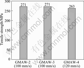
Fig. 5 Tensile strength vs wire feeding speed at travel speed of 8.3 mm/s
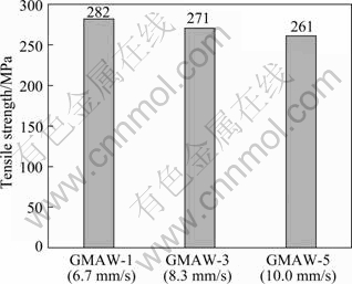
Fig. 6 Tensile strength vs travel speed at wire feeding speed of 110 mm/s
The average tensile strength of joints GMAW-2 and GMAW-3 (271 MPa) is close to that of the base metal (278 MPa), but that of joint GMAW-1 (282 MPa) is stronger than the base metal, although there are pores in the welds from joints GMAW-1 (Fig. 3) and GMAW-2 (Fig. 4(a)). However, it should be noted that the reinforcement of the testing samples is not removed in order to retain the pores. Therefore, the above result is reasonable since the weld reinforcement might compensate for the reduction of the effective cross-sectional area caused by the pores in the weld to bear the load during tensile testing.
All the specimens fracture either in the heat-affected zone or in the base metal during tensile test and the representative photos of the fracture positions are shown in Fig. 7. It can be seen that the fracture occurs in the heat-affected zone for joint GMAW-1 (Fig. 7(a)) or in the base metal for joint GMAW-5 (Fig. 7(b)) although pores exist in both welds.
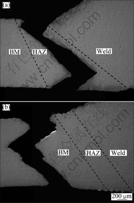
Fig. 7 Fracture positions in joints GMAW-1 (a) and GMAW-5 (b) during tensile test
3.4 Microhardness
The distribution of microhardness in the joint GMAW-1 is shown in Fig. 8. The load is 0.98 N and the duration time is 15 s during testing. The results show that the microhardness in the weld is at the same level or even higher than that in the base metal. However, the microhardness in the heat-affected zone with coarse grains is much lower, which explains why the fracture occurs in the HAZ during tensile testing, although the average strength of this joint is higher than that of the base metal.
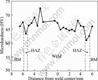
Fig. 8 Distribution of microhardness in joint GMAW-1
Orowan strengthening mechanism indicates that the microhardness of a material can be improved by distributing second phase strengthening particles in the matrix [15]. In this experiment, the weld contains higher Al content than the base metal because the AZ61A magnesium alloy filler wire has larger amount of Al than the AZ31B magnesium alloy base metal. According to Al-Mg binary phase diagram [16], the amount of ��-Mg17(Al, Zn)12 phases is therefore larger in the weld than those in the base metal and heat-affected zone. Consequently, the measured microhardness value in the weld is higher because the ��-Mg17(Al, Zn)12 phases work as the second phase strengthening particles.
4 Conclusions
1) AZ31B magnesium alloy sheets are gas metal arc welded with AZ61A magnesium alloy as the filler metal. Pores mainly appear at the top or bottom part of the weld and cracks could be generated due to the connection of pores. The amount of pores in the weld could be controlled by properly matching the travel speed and wire feeding speed.
2) The tensile strength of the magnesium joints is close to or even higher than that of the base metal despite the existence of pores in the weld. Fracture happens in the heat-affected zone or in base metal during tensile testing.
3) The microhardness in the weld is higher than that in the base metal due to the second phase strengthening effect of the ��-Mg17(Al, Zn)12 phases formed in the weld, but the microhardness value is lower in the heat-affected zone with coarse grains than in the weld and base metal with fine grains.
Acknowledgement
The authors appreciate Professor YANG Chun-li of Harbin Institute of Technology for his help in the welding power supply.
References
[1] LIU Li-ming, MIAO Yu-gang, SONG Gang, LIANG Guo-li. Effect of heat input on microstructure and properties of welded joint in magnesium alloy AZ31B [J]. Transactions of Nonferrous Metals Society of China, 2004, 14(1): 88-92.
[2] MORDIKE B L, EBERT T. Magnesium: Properties-applications- potential [J]. Materials Science and Engineering A, 2001, 302: 37-45.
[3] MUNITZ A, COTLER C, STERN A, KOHN G. Mechanical properties and microstructure of gas tungsten arc welded magnesium AZ91D plates [J]. Materials Science and Engineering A, 2001, 302: 68-73.
[4] PAN Ji-luan. Structure of magnesium alloy and welding [J]. Electric Welding Machine, 2005, 35(9): 1-7. (in Chinese)
[5] HELMUT W, MICHAEL R, BELKACEM B, MICHAEL S. Metal-inert gas welding of magnesium alloys [J]. Welding and Cutting, 2003, 55(2): 80-84.
[6] WANG Hong-ying, LI Zhi-jun. Microstructure and properties of AZ61 magnesium alloy joints produced by laser welding method [J]. The Chinese Journal of Nonferrous Metals, 2006, 10(8): 1388-1393. (in Chinese)
[7] LI Ri-jun, HAO Ning-ning. Process of TIG welding on magnesium alloy [J]. Electric Welding Machine, 2007, 37(2): 70-73. (in Chinese)
[8] ZHAO H, DEBROY T. Pore formation during laser beam welding of die-cast magnesium alloy AM60B-mechanism and remedy [J]. Welding Journal, 2001, 80(8): s204-s210.
[9] LIU L M, SONG G, LIANG G L, WANG J F. Pore formation during hybrid laser-tungsten inert gas arc welding of magnesium alloy AZ31B-mechanism and remedy [J]. Materials Science and Engineering A, 2005, 390: 76-80.
[10] WU S S, XU S X, AN P, FUKUDA Y, NAKAE H. Influence of hydrogen levels on porosity and mechanical properties of Mg alloy castings [J]. International Journal of Cast Metals Research, 2008, 21(1-4): 100-104.
[11] HAFERKAMP H, BACH F R W, BURMESTER I, KREUTZBURG K, NIEMEYER M. Nd:YAG laser beam welding of magnesium constructions [C]//LORIMER G W. Proceedings of the Third International Magnesium Conference. Manchester: The Institute of Materials, 1996: 89-98.
[12] XU N, SHEN J, XIE W D, WANG L Z, WANG D, MIN D. Abnormal distribution of microhardness in tungsten inert gas arc butt-welded AZ61 magnesium alloy plates [J]. Materials Characterization, 2010, 61: 713-719.
[13] CAO X, WALLACE W, POON C, IMMARIGEON J P. Research and progress in laser welding of wrought aluminum alloys-part 1: Laser welding processes [J]. Materials Manufacturing Processes, 2003, 18(1): 1-22.
[14] GAO M, ZENG X Y, TAN B, FENG J C. Study of laser MIG hybrid welded AZ31 magnesium alloy [J]. Science and Technology of Welding and Joining, 2009, 14(4): 274-281.
[15] WANG X H, WANG K S. Microstructure and properties of friction stir butt-welded AZ31 magnesium alloy [J]. Materials Science and Engineering A, 2006, 431: 114-117.
[16] NAYEB-HASHEMI A A, CLARK J B. Phase diagrams of binary magnesium alloys [M]. OH: Metals Park, ASM International, 1988: 370.
AZ31Bþ�Ͻ��ۻ������屣�����������֯����ѧ����
�����1, 2���δ���2������Ⱥ2
1. ��������ҵ��ѧ �Ƚ����������ӹ����ص�ʵ���ң������� 150001��
2. ����������ѧ ���Ͽ�ѧ�빤��ѧԺ������ 116085
ժ Ҫ��ʹ���ۻ������屣�����Ա���þ�Ͻ��ĶԽӡ��ڲ�ͬ���ӹ��ղ����¹۲캸���е������������������׳����Լ����Խ�ͷ����֯����ѧ���ܵ�Ӱ�졣����֯�����������������Ҫ�ֲ��ں��춥����ײ�����������������������������ơ�Ȼ�����ں��ʵĺ��ӹ��ղ����£����IJ������Եõ���Ч���ơ�������Խ����������ͷ��ƽ������ǿ�Ƚӽ���������ĸ�ġ����ڵڶ��� ��-Mg17(Al, Zn)12��ǿ�����ã���������Ӳ�ȸ���ĸ�ġ�
�ؼ��ʣ�þ�Ͻ��ۻ������屣�����������ʣ�����֯���ڶ���ǿ��
(Edited by FANG Jing-hua)
Foundation item: Project (09009) supported by the State Key Laboratory of Advanced Welding and Joining, Harbin Institute of Technology, China
Corresponding author: DONG Hong-gang; Tel: +86-411-84706283, Fax: +86-411-84708389; E-mail: donghg@dlut.edu.cn
DOI: 10.1016/S1003-6326(11)61323-X
Abstract: Wrought magnesium alloy sheets were butt welded with gas metal arc welding process. Pores in the weld were investigated under different welding parameters, the causes of pore formation were systematically disposed, and the effects of porosity on the microstructure and mechanical properties of the joint were analyzed. The microstructure examination shows that the pores mainly appear close to the top or bottom part of the weld, and could connect to each other and lead to the formation of cracks in the welds. However, the pores can be controlled with proper welding parameters. The tensile testing results reveal that the average joint strength is close to or higher than that of the base metal. The microhardness in the weld can be even higher than that in the base metal due to the second phase strengthening of ��-Mg17(Al, Zn)12 formed in the weld.
