
Trans. Nonferrous Met. Soc. China 26(2016) 1546-1554
Hot bend assisted gas forming of AA5083 sheet for making V-shaped trough containing deep uneven concavities
Jung-Sung TANG, Shyong LEE
Department of Mechanical Engineering, National Central University, Taoyuan 32001, China
Received 10 July 2015; accepted 29 December 2015
Abstract:
Employing low pressurized gas for shaping superplastic metal sheets into complex contours has long been adopted in the aero/auto industries and it is commonly recognized as superplastic forming (SPF). The most undesired feature of SPF would be an uneven thickness distribution in the final formed part. However, there are techniques that lessen this disadvantage. Low pressurized gas was used to make a V-shaped trough containing deep uneven concavities using superplastic AA5083. The auxiliary yet influential procedure of mechanically hot bending the flat sheet into a V-shape precedes the gas-forming process. In this first quick hot-bending operation, buckling will occur if the depth of bending exceeds a certain level. The degree of buckling and associated contours will affect the thickness distribution as well as the wrinkling location in the gas-formed product. A better thickness distribution is obtainable at the cost of wrinkle formation. Wrinkling can be purposely arranged to achieve better uniform thickness distribution, but it needs to be located outside the trim line of the gas-formed semi-product. Therefore, it is critical to manipulate the hot bending procedure to yield a suitable pre-form allowing a successful sequential gas-forming process.
Key words:
wrinkle; superplastic forming (SPF); hot-bend assisted gas forming (HBAGF); three-dimensional finite element analysis (FEA);
1 Introduction
The superplastic forming (SPF) technique has long been used to manufacture aero-industrial sheet parts for its merit of low residual stress. BARNES [1] reviewed the significant advances that have taken place over the past 40 years, including alloy development and applications in the aerospace and automotive markets. HEFTI [2] presented a few examples of this technique using the superplastic AA5083 to fabricate sheet parts for commercial planes. One such part is the superplastically formed 737 wing outboard leading edge strakelet, approximately ~610 mm in length and ~380 mm in width, which has a complex geometry without symmetry. The product with sloped sidewalls is ~1200 mm in length and has a ~260 mm opening width, comprising two near- conical shape sinks at two ends. The depth of one sink apex is ~350 mm, which results in the depth/width ratio reaching ~1.4. Conventional SPF of deep and irregular contours can lead to excessive thinning, poor thickness distribution, and wrinkling [3-5]. A number of researchers have reported similar SPF processes. LUCKEY et al [5,6] and TANG et al [7] presented two novel SPF processes, namely, hot-draw mechanical preforming (HDMP) and two-stage gas forming (TSGF). In the first stage of forming in the TSGF process, the material is forced into an engineered preform cavity. Subsequent reversal of gas pressure forces the material into the final part of the cavity. The HDMP process uses a blank holder to control the material flowing into the die during the preforming step. Thus, wrinkling can be suppressed while the material is drawn into the die cavity [5-7]. A study conducted by LIU et al [8,9] used a superplastic-like AA5083 sheet that was almost fully formed at 400 ��C by utilizing the mechanical preforming and blow forming process. In earlier SPF works, a starting shape closer to the desired trough was adopted. The starting sheet was first preformed into a V-shape and then laid inside a saddle-contour die cavity to be gas-formed [3]. Since the processed product was found to be unsatisfactory, the TSGF process was proposed and adopted. The aforementioned 737 strakelet was fabricated with TSGF. However, in the TSGF process, the final thickness distribution over the trough was excessively non-uniform, and the occurrence of wrinkling was an influential negative factor [4]. Therefore, hot bend assisted gas forming (HBAGF), an improved technique, was conceived and adopted to fabricate strakelets.
In this work, we used low pressurized gas to make a V-shaped trough containing deep uneven concavities using superplastic AA5083. An auxiliary yet influential procedure that mechanically hot bends the flat sheet into V-shape precedes the gas forming process. First, the starting flat sheet was laid on top of the lower die for 5 min, and then the cover plate acting as a punch easily bends the sheet into to a V-shape preform, which is hot and soft at this moment. Then, the V-shape preform was clamped tightly to receive pressurized gas and proceed with the superplastic forming task for 30 min. It then emerged as a trough with a contour resembling a Bactrian camel��s back. The desired strakelet contour was cut out along the ending opposite position (EOP) line. In this first quick hot-bending operation, buckling will occur if the depth of bending exceeds certain level. The degree of buckling and its associated preform contour will affect the thickness distribution as well as the wrinkling location in the gas-formed product. Systematic experiments and numerical simulations were conducted to investigate a sub-size model of the strakelet scaled to one-half of the original size. Explicit finite element analysis with LS-DYNA was applied to predicting deformation of the preform and the associated gas-formed wrinkles.
2 Material model
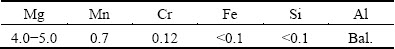
The superplastic aluminum alloy, AA5083, has various applications in commercial SPF because of its special characteristics such as low cost, moderate strength, good corrosion resistance, as well as its forming and processing characteristics [10,11]. A sheet of aluminum alloy AA5083 with a nominal thickness of ~1 mm or ~2.5 mm was used in this study. It had been previously processed to have a stable grain size of ~8 ��m. Its chemical composition is summarized in Table 1.
Table 1 Chemical composition of superplastic AA5083 alloy (mass fraction, %)
The earliest constitutive model was proposed by Backofen and other investigators in power law form [12]. A widely used constitutive model relates flow stress, strain rate, and effective strain through power law [13]:
 (1)
(1)
where �� is the effective flow stress,  is the effective strain rate, �� is the effective strain, K is a constant (here, K=159.5), m is the strain rate sensitivity exponent (here, m=0.48), and n is the strain-hardening exponent (here, n=0.088). The high temperature deformation behavior of the alloy was characterized previously by LAN et al [4] and TAGATA et al [14] using high temperature tensile tests with curve fitting parameter extraction. The coefficients in this study represent the superplastic response at a temperature of ~500 ��C and strain rate of ~0.001 s-1.
3 Simulation setup
In this study, finite element analysis with LS-DYNA was applied to predicting deformation of the gas-formed wrinkles and thickness distribution along the edge of the strakelet. WANG et al [15] studied a multi-step methodology to improve the efficiency of blank optimization using LS-DYNA. LU [16] successfully predicted the wrinkled flange in the cylindrical drawing process, the circle hole expansion in the bore expanding process, and the square cup in the square cup drawing by LS-DYNA. LUO et al [6] and TANG et al [7] used a long rectangular die and commercial FEA codes established by correlation with SPF trials from an industrial SPF process. The codes were used for their predictive accuracy. These studies are early examples of investigations on TSGF processes.
LUCKEY et al [17] demonstrated that shell elements are more computationally viable for 3D analysis, where a sheet is gas formed over a small radius. Therefore, explicit finite element analysis (FEA) with LS-DYNA using shell elements for the working sheet and dies was applied to capturing the overall deformation profile and to predicting the occurrence of wrinkles. The die was modeled as an analytical rigid surface. For the formed subsize trough (scaled down to 1/2), the blank had initial dimensions of 500 mm �� 600 mm and was discretized with a mesh size of 2 mm. The model material was applied using the rate sensitive power law plasticity model [6,17]. In all modeling analyses, automatic surface-to-surface contact was used to define the contact interface between the sheet and dies. The Coulomb friction model with a friction coefficient of 0.2 was used in the interfacial boundary condition.
During simulation of the hot-bend stage, the boundary condition for the lower die was fixed while the blank was unconstrained. The upper die was applied vertically with constant speed ~0.58 mm/s within a prescribed stroke (~175 mm). During simulation of the gas-pressure forming stage, the blank was clamped on all sides. No material flowed into the cavity, and the pressure load was uniform. The nodes on the perimeter of each sheet were constrained to simulate the clamping of the sheet between the die halves. A pressure cycle identical to that of the experiments was applied on the blank��s upper surface.
4 Experimental
A press (Murdock, E910207; 24"��24", 100-ton clamping force), which is basic equipment for gas forming, was used. It provided a stable and uniform high-temperature environment. The press offered a sufficient clamping force to achieve close contact between the component die (also called lower die), the edge of the blank sheet, and the cover plate with a hot-bend tool (also called upper die). Two types of forming die were adopted in this study, and the main difference between the two dies was the depth of the V-shaped lower die. One forming die had a depth that reached ~12.9 mm below the saddle (defined as Case A, Fig. 1(a)), and the other one had a depth that reached ~4.2 mm below the saddle (defined as Case B, Fig. 1(b)). Case A and Case B used identical lower dies, and adapter blocks were added on both sides of die B to shallow the V-shaped trough (Fig. 1(c)). In order to facilitate fabrication and assembly, a split lower die was designed and used. The design of the upper die was in line with the V-shaped curves in the lower die. During the hot-bend stage, the blank holder [18], punch geometry, and depth are important to the drawability [19] of the material, since they can significantly enhance formability in fast forming. For the upper die, a cover plate with a hollow cylinder functionally resembling a punch was used to aid the hot-bend preforming process, as indicated in Fig. 2. The variations in the coefficient of friction between the dies and the sheet directly affect the stress distribution and microstructure evolution of the material being processed [20]. The cover plate also acted as a blank holder, sealing the gas and enabling hot preforming. A lubricant, made of oil-based graphite, was applied to the surfaces of the blank and the lower die to facilitate sliding.
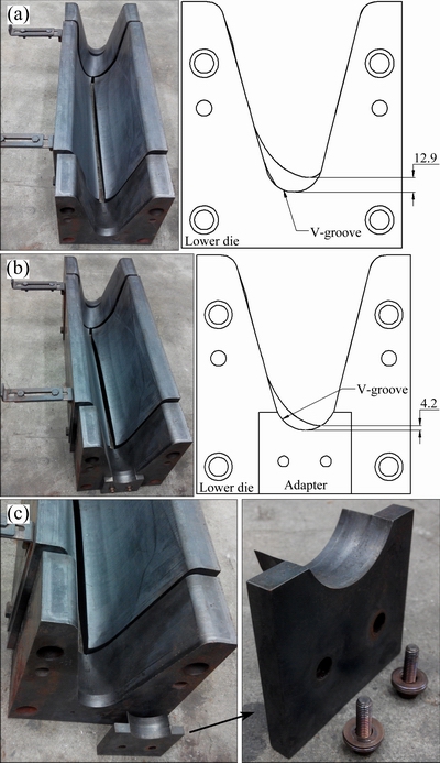
Fig. 1 Photographs of lower die for Case A (a) and Case B (b) used in HBAGF (left) and right side view (right) adapter of Case B (c)

Fig. 2 Photograph of upper die used in HBAGF
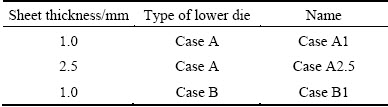
The forming sequence of the HBAGF process is shown in Fig. 3. The experimental procedure began by heating the set of upper and lower dies to 500 ��C; the dies were opened after the temperature stabilized. A flat Al sheet with ~1 or ~2.5 mm in thickness was laid on top of the component die for ~5 min and then uniformly heated at 500 ��C. The cover plate, which functioned as a punch, bent the heated and softened sheet easily into a V-shaped preform. This is referred to as the hot-bend stage. The forming stroke was ~175 mm, and the duration was ~5 min. The V-shaped preform was then clamped tightly to receive the pressurized gas and was subjected to SPF for ~30 min. The HBAGF pressure cycle is shown in Fig. 4. The clamping force ensured sealing of the pressurized gas and integration of the blank and dies. In this study, the design of experiment matrix is shown in Table 2.
5 Results and discussion
5.1 Wrinkling during superplastic forming process
Wrinkles formed at two sites in Case A when the experiment was conducted on a ~1 mm-thick sheet (Case A1). One wrinkle formed around the center of the saddle (the highest point of the lower die), and this site lay inside the EOP line. The other wrinkle lay outside the EOP line close to the die entrance (Fig. 5(a)). Such wrinkling locations resemble those of simulation results (Fig. 5(b)). The main reason for wrinkle formation is that the length of the sheet at the saddle is greater than the surface section contour length of the lower die cavity, and as a result, the material cannot fully stretch in the die cavity which leads to wrinkles during the gas-pressure forming stage.

Fig. 3 Forming sequence of HBAGF process
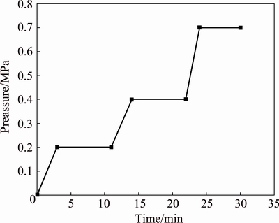
Fig. 4 Pressure cycle for gas forming process
Table 2 Design of experiment matrix
When the same experiment as Case A was conducted on a ~2.5 mm-thick sheet (Case A2.5), a wrinkle still formed at the die entrance outside the EOP line. However, the other wrinkling site inside the EOP line disappeared. Compared with results on ~1 mm-thick sheet, the different wrinkle formation is primarily due to the differing capacity for resisting buckling. A representative completed V-shaped trough containing uneven concavities and the experimental result with a 2.5 mm-thick sheet for Case A is shown in Fig. 6. The hot-bend sheet was cut along Section B to demonstrate the fitting between the sheet and the lower die. The experimental results of 1 mm and 2.5 mm sheets are presented in Figs. 7(a) and (b). At the hot-bending stage, buckling occurred in the vicinity of the saddle due to the fact that it is higher than the bottom of the V-shaped trough. Therefore, the two sides were concaved towards the inside to form an arc. The arcs on section contour of the 1 mm blank had smaller radius of curvature than that of the 2.5 mm one. The simulation results of the gas- forming process for 1 mm and 2.5 mm hot-bend preform sheets are illustrated in Figs. 8(a) and (b). Figure 8(a) shows that in the hot-bend preform sheet, the small arcs could not move and flow under the applied gas pressure at the gas-forming stage and eventually formed wrinkles in the middle of the side. In Fig. 8(b), the flat shape of arcs in the 2.5 mm-thick sheet enables the sheet to be in contact with the die surface from the bottom. A small arc is gradually formed towards the top which is eventually transformed into a wrinkle at the die entrance.
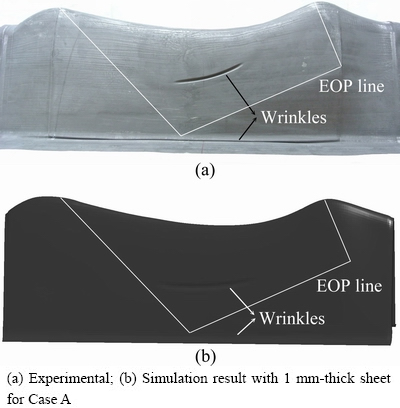
Fig. 5 A formed trough containing wrinkles formed at two sites
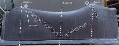
Fig. 6 Completed V-shaped trough containing uneven concavities
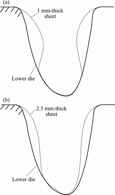
Fig. 7 Experimental result of hot bending contours in Section B with 1 mm- (a) and 2.5 mm- (b) thick sheet for Case A
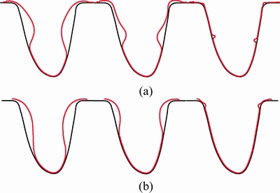
Fig. 8 Simulations of gas-forming process with 1 mm- (a) and 2.5 mm- (b) thick sheets for Case A
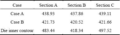
Wrinkles were formed at the die entrance (outside the EOP line) in Case B where the experiment was conducted on a 1 mm-thick sheet (Fig. 9(a)). Such wrinkling locations resemble those of simulation results (Fig. 9(b)). The main reason for wrinkle formation is that the surface section contour length of the sheet at the saddle is slightly greater than the contour length of the die cavity, and as a result, the material does not have sufficient space to stretch. In addition, as the surface section contour length of the sheet at the saddle is slightly greater than the length of the lower die cavity, buckling around the saddle is alleviated at the hot-bending stage. The sheet was concaved towards the inside to appear flat and stretched (Fig. 10). It is different from Case A1 in that no wrinkle occurs inside the EOP line. The contour length of hot-bend sheets and the die��s inner contour length were measured at three different cross sections (Sections A, B, and C in Fig. 6), and the measurements are listed in Table 3. The sheet length at Section B is 4.67% greater than the die contour length in Case A and 0.52% greater in Case B. At Sections A and C, sheet length is less than the die contour length in both cases. As the bending stage causes nonlinear deformation and also as a result of contact behavior at Section B and the variation of clamping restraints around the sheet, the sheet contour length varies slightly at different sections.
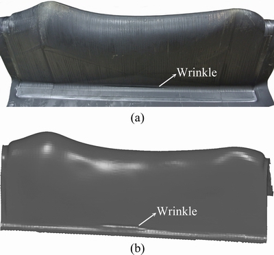
Fig. 9 Formed trough containing wrinkles occurred at two sites experimental (a) and simulation results (b) with 1 mm-thick sheet for Case B

Fig. 10 Experimental result of hot bending contours in Section B with 1 mm-thick sheet for Case B
Table 3 Hot-bend contour length vs die inner contour length at sections A, B, and C
5.2 Thickness distribution along edge of strakelet
The experimental measurements of thickness at various locations along the EOP line for Case A1, Case A2.5, and Case B1 are shown in Fig. 11. Point 0 and Point 22 are close to the peak of Section B and Section A, and the thickness was the smallest at these locations. The thicknesses at the two points are ~0.76 mm and ~0.72 mm in Case A1, ~0.62 mm and ~0.60 mm in Case B1, and ~1.7 mm and ~1.64 mm in Case A2.5. It can be noticed by comparing Case A1 and Case B1 for 1 mm-thick sheet that owing to the greater depth of the V-shaped trough in Case A, the sheet is in closer contact with the die surface, resulting in less elongation and less thinning compared with Case B. The thinning decreases from point 0 to 6 and from point 22 to 15. From point 7 to 16, the thickness of the formed product is almost identical to the thickness of the original sheet. This region is where the sheet contour length is greater than the die contour length. In reference to the specifications from the clients for such products, both Case A and Case B can meet the requirements. Although the percentage of thinning in Case A is slightly less than that in Case B, thinner sheets (e.g., the 1 mm sheet in this study) are more susceptible to undesired wrinkling. Wrinkling inside the EOP line is a significant and unacceptable defect.
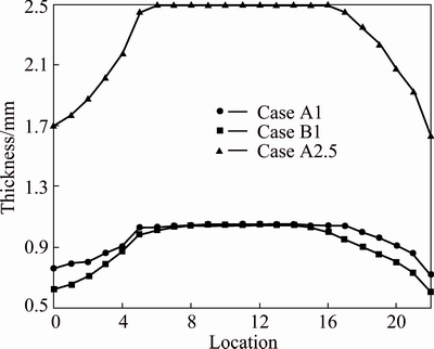
Fig. 11 Thickness distribution around EOP line
The thickness distributions for sheets in Case A1 and Case B1 after cutting along section A and section C are presented in Figs. 12(a) and (b), respectively. The amount of thinning increases from points A1 to A13 (C1 to C14) and from points A26 to A14 (C24 to C15) in both experiments. This is mainly due to the fact that the contour length of hot-bend sheet in this region is similar to that of the die surface and also that the contours are straight. In the gas-forming process, the material comes into contact with the die before it can fully stretch. Due to the viscous effect between the material and the die surface, the material does not flow easily which results in less thinning. After the material on both sidewalls is in contact with the die, material at the bottom continues to extend into the cavity. The thinnest locations, which coincide with the top of humps, are points A14 and C14. It can be discovered by comparing the formed parts that the thickness in Case B1 is less than that in Case A1 at all points. For Case B1, the maximum thickness discrepancy occurs at the lowest point in the die cavity, with approximately ~0.48 mm at point A13 and ~0.53 mm at point C14. The depth of the V-shaped bend in Case B is about ~8.5 mm less than Case A, with the thickness ~0.13 mm and ~0.20 mm less. This solved the problem of undesired wrinkling inside the EOP line.
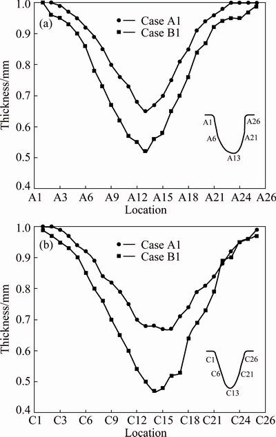
Fig. 12 Thickness distribution along Section A (a) and Section C (b) in Case A1 and Case B1
5.3 Correlation with simulation
The thinning percentage (e) was calculated by
 (2)
(2)
where tpart is the part thickness and t0 is the initial material thickness. Some investigators [5,7,17] indicated that the good correlation in thickness prediction between simulation and experiment was achieved, with the maximum difference of no greater than 5% between the predicted and experimentally measured thinning. Figure 13 shows the experimental and simulated thickness profiles for Cases A1, A2.5 and B1 around the EOP line for the strakelet front side at points 0 to 22. The simulation results agree very well with the experiments and the maximum deviations are ~3.9%, ~3.8%, and ~3.7% at point 21 for Case A1, A2.5 and B1, respectively. In this study, a satisfactory maximum difference of no greater than 4.0% between the predicted and experimentally measured thinning was obtained. Locations with a higher percentage of thinning also have greater level of errors. With the exceptions of points 18 and 19 in Case B1 simulation results are slightly greater than the experimental outcomes.

Fig. 13 Experiment (EXP) and simulation (FEA) thinning percentage around EOP line
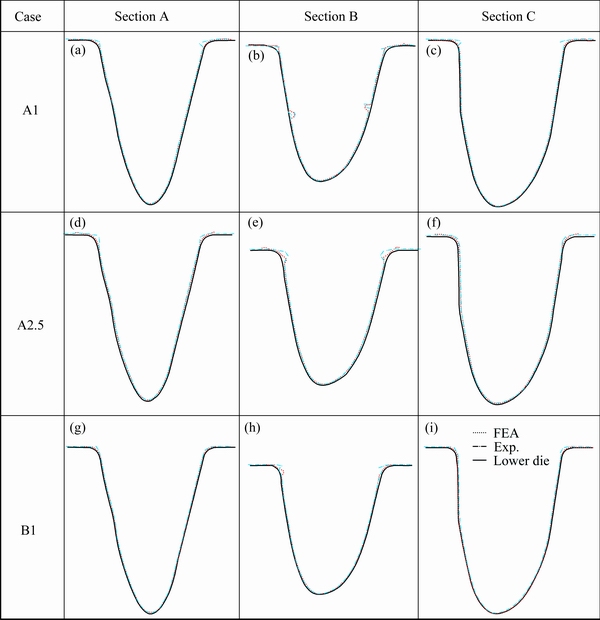
Fig. 14 Experimental and simulation results of gas forming contours in Sections A, B, and C for Case A1 (a, b, c), A2.5 (d, e, f), and B1 (g, h, i)
The contours of part after gas forming between experiment and simulation are presented in Fig. 14. It can be seen that computer simulation is reasonably accurate in reflecting the experimental results. The three-dimensional finite element analysis software LS-DYNA may be used to accurately model the wrinkling occurrence and sites of aluminum sheet during superplastic forming. The power law equation can be used as a constitutive model for superplastic forming.
6 Conclusions
1) HBAGF improves the conventional SPF manufacturing process and the poor thickness distribution encountered in TSGF. Increasing the V-shaped bending depth to force the preformed sheet into the die cavity can effectively improve the thickness distribution. However, excessive bending causes the sheet section contour length to be greater than that of the lower die in some regions, resulting in the formation of wrinkles. The wrinkling location can be controlled by designing an appropriate bending depth so that wrinkles are located outside the trim line in the formed products, thus not affecting their quality.
2) Simulation results from the three-dimensional finite element analysis software LS-DYNA are in good agreement with the experimental results in both the hot-bending and the gas-forming stages. LS-DYNA can effectively aid the design of the forming die and the prediction of wrinkling locations. It can also facilitate understanding of the evolution of the material during the SPF process.
3) Simulation and experimental results indicate that material model in the power law form is applicable to the simulation of SPF. Employing shell 163 can accurately predict the rate of thinning of the sheet material.
4) Compared with conventional SPF and TSGF, HBAGF features shorter forming durations (~30 min), a lower overall manufacturing cost, simple design of the forming die, and modular design. The resulting molds possess interchangeability and the ability to be redesigned.
References
[1] BARNES A J. Superplastic forming 40 years and still growing [J]. Journal of Materials Engineering and Performance, 2007, 16(4): 440-454.
[2] HEFTI L D. Commercial airplane applications of superplastically formed AA5083 aluminum sheet [J]. Journal of Materials Engineering and Performance, 2007, 16(2): 136-141.
[3] LEE S, LAN H C, LEE J, WANG J Y, HUANG J C, CHU C L. Gas forming a V-shape aluminum sheet into a trough of saddle-contour [J]. Journal of Materials Engineering and Performance, 2012, 21(11): 2290-2294.
[4] LAN Hsien-chin, FUH Yiin-kuen, LEE Shyong, CHU Chun-lin, CHANG Tien-chan. Two-stage superplastic forming of a V-shape aluminum sheet into a trough with deep and irregular contour [J]. Journal of Materials Engineering and Performance, 2013, 22(8): 2241-2246.
[5] LUCKEY S G, FRIEDMAN P A, WEINMANN K J. Design and experimental validation of a two-stage superplastic forming die [J]. Journal of Materials Processing Technology, 2009, 209: 2152-2160.
[6] LUO Y, LUCKEY S G, FRIEDMAN P A, PENG Y. Development of an advanced superplastic forming process utilizing a mechanical pre-forming operation [J]. International Journal of Machine Tools and Manufacture, 2008, 48: 1509-1518.
[7] TANG Jung-sung, FUH Yiin-kuen, LEE Shyong. Superplastic forming process applied to aero-industrial strakelet: Wrinkling, thickness and microstructure analysis [J]. The International Journal of Advanced Manufacturing Technology, 2015, 77: 1513-1523.
[8] LIU J, TAN M J, AUEULAN Y, JARFORS A E W, FONG K S, CASTAGNE S. Superplastic-like forming of non-superplastic AA5083 combined with mechanical pre-forming [J]. The International Journal of Advanced Manufacturing Technology, 2011, 52: 123-129.
[9] LIU Jun, TAN Ming-jen, LIM Chao-voon S, CHUA Beng-wah. Process optimization and microstructural development during superplastic-like forming of AA5083 [J]. The International Journal of Advanced Manufacturing Technology, 2013, 69: 2415-2422.
[10] HIRSCH J. Recent development in aluminium for automotive applications [J]. Transactions of Nonferrous Metals Society of China, 2014. 24(7): 1995-2002.
[11] WANG Hui, LUO Ying-bing, FRIEDMAN P, CHEN Ming-he, GAO Lin. Warm forming behavior of high strength aluminum alloy AA7075 [J]. Transactions of Nonferrous Metals Society of China, 2012, 22(1): 1-7.
[12] BACKOFEN W A, TURNER T R, AVERY D H. Superplasticity in Al-Zn alloy [J]. ASM Transactions, 1964, 57: 980.
[13] PADMANABHAN K A, DAVIES G J. Superplasticity [M]. Berlin: Springer, 1980.
[14] TAGATA T, MASTSUO M, IWASAKI H, HIGASHI K. Forming limit diagram for a superplastic 5083 aluminum alloy [J]. Materials Transactions, 2004, 45(8): 2516-2520.
[15] WANG Jyhwen, GOEL Amit, YANG Feng-chen, GAU Jenn-terng. Blank optimization for sheet metal forming using multi-step finite element simulations [J]. International Journal of Advanced Manufacturing Technology, 2009, 40: 709-720.
[16] LU Yuung-hwa. Integration of RP and explicit dynamic FEM for the visualization of the sheet metal forming process [J]. International Journal of Advanced Manufacturing Technology, 2006, 28: 255-261.
[17] LUCKEY S G, FRIEDMAN P A, WEINMANN K J. Correlation of finite element analysis to superplastic forming experiments [J]. Journal of Materials Processing Technology, 2009, 194: 30-37.
[18] RAJU S, GANESAN G, KARTHIKEYAN R. Influence of variables in deep drawing of AA 6061 sheet [J]. Transactions of Nonferrous Metals Society of China, 2010, 20(10): 1856-1862.
[19] ZHOU Jing, WANG Bao-yu, LIN Jian-guo, FU Lei, MA Wen-yu. Forming defects in aluminum alloy hot stamping of side-door impact beam [J]. Transactions of Nonferrous Metals Society of China, 2014, 24(11): 3611-3620.
[20] MA Wen-yu, WANG Bao-yu, FU Lei, ZHOU Jing, HUANG Ming-dong. Effect of friction coefficient in deep drawing of AA6111 sheet at elevated temperatures [J]. Transactions of Nonferrous Metals Society of China, 2015, 25(7): 2342-2351.
AA5083�����������ѹ�����Ʊ����ƽ��V�β�
������, �� ��
���������ѧ ��е����ѧϵ���� 32001
ժ Ҫ��ʹ�õ�ѹ���������Խ���Ƭ�γɸ��������ѹ㷺Ӧ���ں��ռ�������ҵ�У����ձ鶨��Ϊ���ܳ��η�(SPF)�����ܳ��ε��ŵ�����ͳɱ���ģ�߱������Ʋ��ҳ�Ʒ���еͲ���Ӧ������һ���棬���ܳ��εIJ�Ʒ����ɺ�ȷֲ������ȡ�Ȼ����Ҳ�н��ʹ�ȱ��ļ��������ó�����AA5083����Ե�ѹ����ʹV�Ͱ�ij��������ƽ��V�Ͳۡ���ʹ�û�е����������ʹ��ij�V�ͺ��ٽ������������������Σ������������ȳ���һ��ˮƽ�����´����������ͼ���������Ӱ�����γɲ�Ʒ��ȷֲ��Լ�������λ�ã����ǽ���ø��õĺ�ȷֲ������ɾ��ɹ滮�Դﵽ���õľ��Ⱥ�ȷֲ���������λ����Ҫ�����ڰ��Ʒ�������⡣��ˣ��������������Ի��һ�����ʵ�Ԥ���ΰ�ĵ�������������������Ҫ�ġ�
�ؼ��ʣ����ޣ����ܳ��Σ������������������Σ���ά����Ԫ����
(Edited by Xiang-qun LI)
Corresponding author: Jung-Sung TANG; Tel: +886-3-4267324; Fax: +886-3-4254501; E-mail: 993403011@cc.ncu.edu.tw
DOI: 10.1016/S1003-6326(16)64260-7
Abstract: Employing low pressurized gas for shaping superplastic metal sheets into complex contours has long been adopted in the aero/auto industries and it is commonly recognized as superplastic forming (SPF). The most undesired feature of SPF would be an uneven thickness distribution in the final formed part. However, there are techniques that lessen this disadvantage. Low pressurized gas was used to make a V-shaped trough containing deep uneven concavities using superplastic AA5083. The auxiliary yet influential procedure of mechanically hot bending the flat sheet into a V-shape precedes the gas-forming process. In this first quick hot-bending operation, buckling will occur if the depth of bending exceeds a certain level. The degree of buckling and associated contours will affect the thickness distribution as well as the wrinkling location in the gas-formed product. A better thickness distribution is obtainable at the cost of wrinkle formation. Wrinkling can be purposely arranged to achieve better uniform thickness distribution, but it needs to be located outside the trim line of the gas-formed semi-product. Therefore, it is critical to manipulate the hot bending procedure to yield a suitable pre-form allowing a successful sequential gas-forming process.
