
J. Cent. South Univ. (2016) 23: 1224-1231
DOI: 10.1007/s11771-016-0372-9

Analysis on optimal working fluid flowrate and unstable power generation for miniaturized ORC systems
LIU Ke-tao(������)1, 2, ZHU Jia-ling(�����)1, 2, HU Kai-yong(������)1, 2, WU Xiu-jie(�����)1, 2
1. Key Laboratory of Efficient Utilization of Low and Medium Grade Energy (Tianjin University),
Ministry of Education, Tianjin 300072, China;
2. Tianjin Geothermal Research and Training Center, School of Mechanical Engineering, Tianjin University,Tianjin 300072, China
 Central South University Press and Springer-Verlag Berlin Heidelberg 2016
Abstract:
For efficient utilization of a limited geothermal resource in practical projects, the cycle parameters were comprehensively analyzed by combining with the heat transfer performance of the plate heat exchanger, with a variation of flowrate of R245fa. The influence of working fluid flowrate on a 500W ORC system was investigated. Adjusting the working fluid flowrate to an optimal value results in the most efficient heat transfer and hence the optimal heat transfer parameters of the plate heat exchanger can be determined. Therefore, for the ORC systems, optimal working fluid flowrate should be controlled. Using different temperature hot water as the heat source, it is found that the optimal flowrate increases by 6-10 L/h with 5 �� increment of hot water inlet temperature. During experiment, lower degree of superheat of the working fluid at the outlet the plate heat exchanger may lead to unstable power generation. It is considered that the plate heat exchanger has a compact construction which makes its bulk so small that liquid mixture causes the unstable power generation. To avoid this phenomenon, the flow area of plate heat exchanger should be larger than the designed one. Alternatively, installing a small shell and tube heat exchanger between the outlet of plate heat exchanger and the inlet of expander can be another solution.
Key words:
1 Introduction
In the past decades, recovery of waste heat has got increasing attention all over the world with the raising awareness of energy conservation. Through statistical investigations, more than half of the waste heat in industry is low-grade heat, the temperature of which is less than 370 ��C. Conventional cycles can not make use of this kind of exhaust, while ORCs in which the working fluid is organic fluids instead of water have performed extremely well in recovering low grade waste heat [1-2].
Varieties of ORC systems have been studied and widely applied in the utilization of solar, geothermal, biomass, engine exhaust gases, and many other waste heat recoveries. Researches have been carried out to optimize the performance of ORCs by examining the cycle parameters, such as pressures and temperatures. Kuo et al [3] analyzed the system performance of a 50 kW ORC system subjected to influence of various working fluids. Dai et al [4] conducted a comparative study on ORCs with conventional Rankine systems and the advantages of ORCs were shown.
Recent reviews mainly focus on screening working fluids in terms of the performance of the whole systems. HUANG et al [5], Wang et al [6] and Wang et al [7] analyzed the effects of working fluids on ORCs and R245fa was proven to be one of the best working fluids. In addition, the configuration of the components has strong influence on the efficiency of ORCs. However, many ORCs are designed by experience and there is none certain principle on the design of ORC systems so far. Heat exchangers are essential components of ORCs. Usually, they are often designed based on experience, so that the configuration won��t always be the most optimal. Over the past decades, the main heat exchanges have been compared with each other and their characteristics have been comprehensively summarized. However, most experiments are about single phase water-to-water heat transfer. In the recent years, several authors have carried out some experiments using organic fluids.  et al [8] reported that in the ORCs using some organic fluids as working fluids, plate heat exchangers performed better than shell-and-tube heat exchangers. Hsieh and Lin [9-10] measured the evaporation heat transfer coefficient and associated frictional pressure drop in a vertical plate heat exchanger with a chevron angle of 60�� for refrigerant R-410A. They showed how the mean vapor quality, the mass flux and the heat flux impact heat transfer coefficient and frictional pressure drop. Empirical correlations are provided for heat transfer coefficient and frictional pressure drop for R-410A in the plate heat exchanger. Yan and Lin [11] investigated the evaporation heat transfer coefficient and pressure drop for refrigerant R-134a flowing in a plate heat exchanger. Empirical correlations were proposed for heat transfer coefficient and frictional pressure drop for R-134a in the plate heat exchanger. Khan et al [12] carried out experiments to obtain heat transfer and pressure drop data about evaporation of liquid ammonia in a commercial plate heat exchanger for symmetric 60��/60�� chevron angle plates. In addition, two-phase Nusselt number and friction factor correlations were also proposed. However, study about R245fa together with the components of ORCs and cycle parameters is very few.
The performance of ORCs is closely associated with their components and the cycle parameters. Therefore, the system and its components should be considered together to obtain more optimal performance. Medium and low temperature geothermal energy is widely accessible and usually considered to be renewable and environmental resource [13-15].
In the practical projects, parameters of available geothermal resource are limited, including the outlet temperature and the flowrate of hot water, so that what can be adjusted is the flowrate of working fluid. In this study, an experiment subjected to the limited flowrate of hot water is implemented using R245fa as working fluid, aiming at optimal flowrate of working fluid. Moreover, the cause of unstable power generation is studied.
2 Mathematical modeling
The modeling of the ORC system is based on the first and second laws of thermodynamics. The equations needed to deduce the target parameters are shown as follows:
2.1 Heat coefficient
The heat transfer rate respectively in the preheater and the evaporation is calculated from
 (1)
(1)
 (2)
(2)
 (3)
(3)
 (4)
(4)
 (5)
(5)
 (6)
(6)
where Q, W and h respectively represent heat transfer rate, flow rate and enthalpy; Subscripts e, p, w and rare for evaporation, preheat, hot water and refrigerant and the numbers indicate the corresponding point in the two figures; Subscript a stands for average value.
The overall heat transfer coefficient Ue and Up between the hot water and the cold refrigerant can be deduced from
 (7)
(7)
 (8)
(8)
where A is the heat transfer area of the plate or tube. The log mean temperature difference (LMTD) is calculated from
 (9)
(9)
 (10)
(10)
where
 (11)
(11)
 (12)
(12)
 (13)
(13)
 (14)
(14)
The evaporation heat transfer coefficient in the flow of R245fa is determined from
 (15)
(15)
 (16)
(16)
where hr and hw are the heat transfer coefficients of the refrigerant the water, respectively; RwallA is the wall thermal resistance [16].
2.2 Friction factor
The friction pressure drop is calculated from
 (17)
(17)
 (18)
(18)
 (19)
(19)
where ��Pexp, ��Pa, ��Pele [17] and ��Pj mean the measured total pressure drop, the acceleration pressure drop, the pressure losses at the evaporation inlet and exit manifolds and ports and the elevation pressure rise, respectively; vm is the specific volume of the vapor- liquid mixture, which is calculated from
 (20)
(20)
The pressure drop in the inlet and outlet manifolds and ports is calculated from [18]
 (21)
(21)
where um is the mean flow velocity.
 (22)
(22)
The acceleration pressure drop and the pressure losses at the evaporation inlet and exit manifolds and ports are as small as 1%-3% of the total pressure drop.
2.3 System parameters
The net power output, the thermal efficiency and the exergy efficiency show how the ORC system performs using plate heat exchangers or shell-and-tube heat exchangers.
The power output of the ORC system is calculated from
 (23)
(23)
The thermal efficiency of the ORC system is calculated from
 (24)
(24)
where ��th is the thermal efficiency.
The exergy efficiency of the ORC system is calculated from
 (25)
(25)
 (26)
(26)
 (27)
(27)
 (28)
(28)
where Ex means exergy and I is the irreversibility rate.
3 Experimental apparatus and procedures
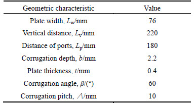
The plate heat exchanger used as evaporation in the experiment is shown in Figs. 1-3. Figure 4 and Table 1 show the geometric characteristics of plates. There are five independent loops: a thermal oil loop, three water loops (one for preheater, one for evaporation and a cold water loop) and a refrigerant loop.
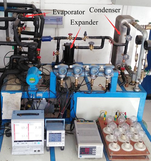
Fig. 1 Experimental system
An electric heating furnace is installed as the heat source and supplies heat to the preheater and the evaporation through a thermal oil loop and two water loops. The heat exchangers between two loops are plate heat exchangers.
The refrigerant loop contains a preheater, an evaporation (plate heat exchanger), an expander, a condenser, a receiver, a pump and some data collectors. A hydraulic diaphragm metering pump controls the refrigerant flowrate and delivers the subcooled refrigerant to the preheater. To measure the flow rate, a mass flow meter is installed in the inlet of the pump. The subcooled refrigerant is heated in the preheater before entering into the evaporation so that there is sufficient space for more vapor. Then, the superheated vapor moves into the scroll expander to generate power. Eventually, the exhaust is condensed and subcooled by the condenser.
A countercurrent cooling tower is used in the cooling cycle. A 1.5 kW pump drives the water in this loop with a water flow meter measuring the flux.
The data acquisition system contains a digital power meter, an agilent system, four vortex flow meters and some other temperature and pressure collectors.
4 Results and discussion
Based on the practical application, the flowrate of hot water is constant. For studying the influence of heat exchangers together with cycle parameters in the present 500 W ORC system, two variables are adjusted:
1) One is the temperature of heat source, including 95 ��C, 100 ��C, 105 ��C and 110 ��C.
2) The other is the flowrate of refrigerant, controlled by the pump.
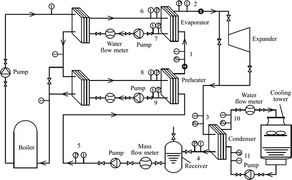
Fig. 2 Schematic of 500 W organic Rankine cycle system
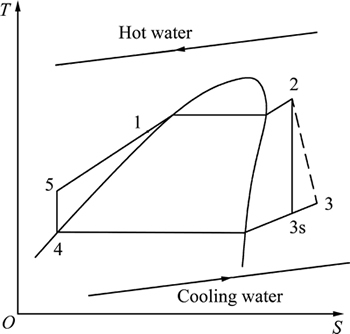
Fig. 3 T-s diagram of 500 W ORC system

Fig. 4 Geometric characteristics of plates
4.1 Cycle parameters
Figure 5 shows the effects of the flowrate of working fluid on the cycle parameters. In practical project, the flowrate of hot water is limited. Therefore, with the increasing of the flowrate of working fluid, the degree of superheat decreases on each occasion of heat source-inlet temperature and it is seen in Fig. 5(a) that the decreasing rate is similar. Figures 5(b) and (c) show the evaporation temperature and evaporation pressure rise with increasing flowrate of working fluid and the growth rate slows down gradually. Another difference in all of these three figures is that higher inlet temperature of hot water makes the degree larger with the same flowrate of working fluid.
Table 1 Geometric characteristics of plates in the present study
4.2 Heat transfer parameters
Figure 6 reports the effect of working fluid flowrate on the heat transfer parameters. In Figs. 6(a) and (b), variations of the overall heat transfer coefficient and the working fluid heat transfer coefficient with the increasing of working fluid flowrate are almost same. They all rise to maximum values and then decrease. And the heat source inlet temperature has no certain influence on the optimal coefficient, either the overall or the working fluid heat transfer coefficient. For this system, the inlet temperature at which the values of each coefficient go from the largest to the lowest in turn are 100 ��C, 110 ��C, 95 ��C and 105 ��C. Meanwhile, with the same flowrate of working fluid, there is no regular change with the heat source inlet temperature. In Figs. 7(c) and (d), the fiction pressure drop and the pinch point temperature decrease to minimum values at first and then rise. The minimum values in both figures get larger with higher inlet temperature. The influence of the inlet temperature gets weaker when the flowrate increases subsequently.
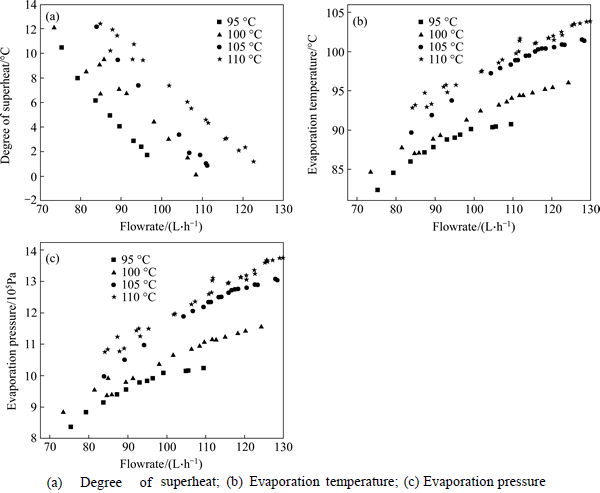
Fig. 5 Effects of R245fa flowrate on cycle parameters:
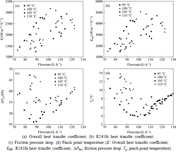
Fig. 6 Effects of R245fa flowrate on heat transfer:

Fig. 7 Effects of flowrate of R245fa on system:
According to eqs. (7) and (15), the variable factor influencing each heat transfer coefficient with the changing working fluid flowrate is the average heat transfer rate. It reveals that adjusting the working fluid flowrate to an optimal value makes the heat transfer most efficient. As a result of the most efficient heat transfer, optimal pinch-point temperatures can be obtained. The flowrate also affects the Reynolds number. Heat transfer and friction pressure drop are influenced by Reynolds number so that the optimal flowrate should be controlled. However, because it is two phase flow in the evaporator, the Reynolds number can be calculated correctly.
4.3 System parameters
4.3.1 Power generation
Figure 7(a) shows the variation of the power generation with the working fluid flowrate raised from 70 L/h to 140 L/h at different inlet temperatures of heat source. It can be clearly observed that with the increase of the flowrate of R245fa, the power generation increases to a maximum value and then declines under every circumstance of inlet temperature of heat source. Before the power generation declines, the temperature of heat source has little influence. However, the maximum values of power generation and the values with the continual increasing flowrate of R245fa are affected by the degree of inlet temperature. The higher the temperature is, the greater the power can be obtained.
4.3.2 Thermal efficiency and exergy efficiency
Figures 7(b) and (c) show how the flowrate of working fluid affects the thermal efficiency and the exergy efficiency respectively. Both thermal efficiency and exergy efficiency under each condition of different inlet temperatures of heat source increase to optimal values with increasing flowrate of R245fa. Next, with the continually increasing R245fa flowrate, each thermal efficiency declines in a greater rate than the growth, so does the exergy efficiency. Moreover, higher temperature of heat source is corresponding to larger thermal efficiency but not always corresponding to larger exergy efficiency. It is worth noting that under the hot water inlet temperature of 110 ��C, the thermal efficiency and the exergy efficiency rise to maximum values all of a sudden. For the thermal efficiency, higher hot water inlet temperature meets larger optimal value. But for the exergy efficiency, there is an exception that the value at the inlet temperature of 100 ��C becomes larger than the one at 105 ��C.
The factors determining the thermal efficiency and the exergy efficiency consist of the superheat degree, the vapor quality, the inlet temperature and so on. These factors are affected by the working fluid flowrate. As analyzed above, with the increasing working fluid flowrate, the superheat degree declines and the vapor quality increases. Also, it makes the heat transfer more efficient. After the flowrate raised to optimal values, liquid refrigerant mixes in the working fluid so that the vapor quality deceases, the inlet temperature decreases and other factors are affected. As a result, the power generation deceases and then each efficiency decreases.
4.3.3 System response
In this experiment, hot water inlet temperature and cooling water inlet temperature are kept constant and the flowrate of R245fa is raised. As shown in Fig. 8, with increasing the working fluid flowrate the evaporation temperature, the evaporation pressure and the outlet temperature of either heat source or cooling source keep stable. However, the decrease of the degree of superheat below about 10 ��C causes the system and the expander isentropic unstable.
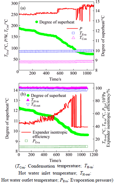
Fig. 8 Response of 500 W system:
In order to explain this phenomenon, a visual window is installed at the outlet of the plate heat exchanger. As shown during the experiment, the unstable power generation may relate to the mixture of liquid. The area of this evaporation is designed just matching the heat transfer so that the interspace for working fluid is small owing to the special characteristic of plate heat exchanger. Therefore, raising the flowrate of working fluid leads to the mixture of liquid.
5 Conclusions
1) Considering the limited conditions of heat source in practical projects, adjusting the working fluid flowrate to an optimal value makes the heat transfer most efficient and then the optimal heat transfer parameters can be obtained, such as the largest overall heat transfer coefficient and working fluid heat transfer coefficient, as well as the lowest friction pressure drop and pinch point temperature.
2) Because the liquid refrigerant mixes in the working fluid, it makes the quality of working fluid worse. The power generation decreases and then the thermal efficiency and the exergy efficiency decrease. Therefore, for the ORC systems, optimal working fluid flowrate should be controlled.
3) The optimal flowrates of R245fa for the 500 W ORC system corresponding to the heat source inlet temperatures of 95, 100, 105, 110 ��C are 99.24, 109.66, 115.88 and 122.61 L/h, respectively. The flowrate should be raised by 6-10 L/h with 5 ��C increment of the hot water inlet temperature.
4) If the area of plate heat exchanger is designed just enough, when the degree of superheat is below about 10 ��C, liquid may mix inside at the outlet of plate heat exchanger, as a result of the small space and the high speed of working fluid flowrate. To avoid this phenomenon, the flow area of plate heat exchanger should be larger than the designed one. Alternatively, installing a small shell and tube heat exchanger between the outlet of plate heat exchanger and the inlet of expander can be another solution.
References
[1] Hung T, Shai T, Wang S. A review of organic Rankine cycles (ORCs) for the recovery of low-grade waste heat [J]. Energy, 1997, 22: 661-667.
[2] Wei Dong-hong, Lu Xue-sheng, Lu Zhen, Gu Jian-ming. Performance analysis and optimization of organic Rankine cycle (ORC) for waste heat recovery [J]. Energy Conversion and Management, 2007, 48: 1113-1119.
[3] Kuo Chi-ron, Hsu Sung-wei, Chang Kai-han, Wang Chi-chuan. Analysis of a 50kW organic Rankine cycle system [J]. Energy, 2011, 36(10): 5877-5885.
[4] Dai Y, Wang J, Gao L. Parametric optimization and comparative study of organic Rankine cycle (ORC) for low grade waste heat recovery [J]. Energy Conversion and Management, 2009, 50(3): 576-582.
[5] Huang X Y, Wang H Y, Wu Z, Zhu T,Wu J Z. Selection of working fluids for organic rankine cycle (ORC) in waste heat power generation system [C]// International Conference on MaterialsforRenewable Energy and Environment (ICMREE). Beijing: China Academic Journal Electronec Publishing House, 2013: 774-779.
[6] Wang E H, Zhang H G, Fan B Y, Ouyang M G, Zhao Y, Mu Q H. Study of working fluid selection of organic Rankine cycle (ORC) for engine waste heat recovery [J]. Energy, 2011, 36: 3406-3418.
[7] Wang D Y, Pei G, Li J, Li Y Z, Ji J. Analysis of working fluid for organic Rankine cycle [C]// International Conference on MaterialsforRenewable Energy and Environment. Beijing: China Academic Journal Electronec Publishing House, 2011: 109-114.
[8] W, BEN L, WILLIAM D. Comparison of shell-and-tube with plate heat exchangers for the use in low-temperature organic Rankine cycles [J]. Energy Conversion and Management, 2014, 87: 227-237.
[9] Hsieh Y Y, Lin T F. Evaporation heat transfer and pressure drop of refrigerant R-410A flow in a vertical plate heat exchanger [J]. ASME J Heat Transfer, 2003, 125: 852-857.
[10] Hsieh Y Y, Lin T F. Saturated flow boiling heat transfer and pressure drop of refrigerant R-410A in a vertical plate heat exchanger [J]. International Journal of Heat and Mass Transfer, 2002, 45: 1033-1044.
[11] Yan Y Y, Lin T F. Evaporation heat transfer and pressure drop of refrigerant R-134a in a plate heat exchanger [J]. ASME J Heat Transfer, 1999, 121: 118-127.
[12] Khan T S, Khan M S, Chyu M C, Ayub Z H. Experimental investigation of evaporation heat transfer and pressure drop of ammonia in a 60��chevron plate heat exchanger [J]. International Journal of Refrigeration, 2012, 35: 336-348.
[13] RUTH S, BRYNHILDUR D,  A. Geothermal energy for sustainable development: A review of sustainability impacts and assessment frameworks [J]. Renewable and Sustainable Energy Reviews, 2015, 44: 391-406.
[14] Wang Zhi-qi, Liu Li-wen, Xia Xiao-xia, Zhou Nai-jun. Dynamic test on waste heat recovery system with organic Rankine cycle [J]. Journal of Central South University, 2014, 21(12): 4607-4612.
[15] Li Tai-lu, Zhu Jia-ling, Zhang Wei. Performance analysis and improvement of geothermal binary cycle power plant in oilfield [J]. Journal of Central South University, 2013, 20: 457-465.
[16] Vlasogiannis P, Karagiannis G, Argyropoulos P, Bontozoglou V. Air�Cwater two-phase flow and heat transfer in a plate heat exchanger [J]. International Journal of Multiphase Flow, 2002, 28: 757-772.
[17] Collier J G. Convective boiling and condensation [M]. 2nd ed. New York: McGraw-Hill, 1982.
[18] Shah R K, Focke W W. Plate heat exchangers and their design theory [M]// Heat Transfer Equipment Design. Washington, DC: Hemisphere, 1988: 227-254.
(Edited by YANG Hua)
Foundation item: Project(2012AA053001) supported by High-tech Research and Development Program of China
Received date: 2015-03-20; Accepted date: 2015-09-23
Corresponding author: ZHU Jia-ling, Professor, master; Tel: +86-22-27401823; E mail: zhujl@tju.edu.cn
Abstract: For efficient utilization of a limited geothermal resource in practical projects, the cycle parameters were comprehensively analyzed by combining with the heat transfer performance of the plate heat exchanger, with a variation of flowrate of R245fa. The influence of working fluid flowrate on a 500W ORC system was investigated. Adjusting the working fluid flowrate to an optimal value results in the most efficient heat transfer and hence the optimal heat transfer parameters of the plate heat exchanger can be determined. Therefore, for the ORC systems, optimal working fluid flowrate should be controlled. Using different temperature hot water as the heat source, it is found that the optimal flowrate increases by 6-10 L/h with 5 �� increment of hot water inlet temperature. During experiment, lower degree of superheat of the working fluid at the outlet the plate heat exchanger may lead to unstable power generation. It is considered that the plate heat exchanger has a compact construction which makes its bulk so small that liquid mixture causes the unstable power generation. To avoid this phenomenon, the flow area of plate heat exchanger should be larger than the designed one. Alternatively, installing a small shell and tube heat exchanger between the outlet of plate heat exchanger and the inlet of expander can be another solution.
