
J. Cent. South Univ. Technol. (2008) 15(s1): 197-201
DOI: 10.1007/s11771-008-345-8
![]()
Fabrication of micro carbon pillar by laser-induced chemical vapor deposition
ZHOU Jian(�� ��)1, LUO Yin-she(��ӭ��)2, LI Li-jun(������)1,
ZHONG Qi-wen(������)3, LI Xin-hua(���»�)1, YIN Shui-ping(��ˮƽ)2
��1. College of Machinery and Electrical, Centre South University of Forestry and Technology, Changsha 410004, China;
2. Institute of Rheological Mechanics and Material Engineering,
Centre South University of Forestry and Technology, Changsha 410004, China;
3. Department of Teaching Affair, Centre South University of Forestry and Technology, Changsha 410004, China)
Abstract��Argon ion laser was used as the induced light source and ethane (C2H4) was selected as the precursor gas, in the variety ranges of laser power from 0.5 W to 4.5 W and the pressure of the precursor gas from 225��133.3 Pa to 680��133.3 Pa, the experiments of laser induced chemical vapor deposition were proceeded for fabrication of micro carbon pillar. In the experiments, the influences of power of laser and pressure of work gas on the diameter and length of micro carbon pillar were investigated, the variety on averaged growth rate of carbon pillar with the laser irradiation time and moving speed of focus was discussed. Based on experiment data, the micro carbon pillar with an aspect ratio of over 500 was built through the method of moving the focus.
Key words:
Laser-induced chemical vapor deposition (LCVD); growing rapid; diameter; microcarbon.��
1 Introduction
With the development of microstructure devices and microelectromechanical systems (MEMS), many moving or suspended spatial structures are required. Although conventional microstructure processing technologies are widely applied for fabrication of two-dimensional microstructure, it is difficult to fabricate three-dimensional microstructure for these technologies. Currently, three-dimensional microstructure within the scope from a few tens of nanometers to several hundreds of microns can be fabricated by using three techniques: electron beam chemical vapor deposition (EB CVD), focused ion beam chemical vapor deposition (FIB CVD) and laser-induced chemical vapor deposition (LCVD). EB CVD and FIB CVD are used for fabrication of microstructures with high aspect ratios and nanoscale structure[1-2]. Some microstructure elements with a diameter range from 0.1��m to 1.0��m, for examples, microciol, microdrill and microbellow which were fabricated by FIB CVD have been reported[3]. However, LCVD has higher deposition rate than EB CVD and FIB CVD and can also directly fabricate the three-dimensional microstructure. In the aspects of the microstructure of the carbon material, besides carbon microvacuume tube that is extensively investigated, using various hydrocarbon, such as methane, ethane, methanol, ethanol and ethylene, as a source gas, LCVD for fabrication of carbon microstructure has been experimented and studied[4], these microstructures fabricated by this method such as microcarbon pillars, are expected to be applicable to electric discharge machining (EDM) and field emission (FE) elements. Thus, the further research about LCVD for fabrication of carbon microstructure is very necessary to understand the influences of laser power, gas pressure, irradiation time and moving speed on growth rate and diameter of deposition, which can help us to obtain the anticipant carbon microstructure[5].
2 Experimental
2.1 Experiment setup
The experiment system used in this research is shown in Fig.1, and the main equipments included in this experimental setup are as follows.
1) Laser: An Ar ion laser was used as induced light source, it was produced by a Sabre TSM20 type continuity laser machine with wavelength from 488 nm to 514.5 nm, and the power changed from 0 to 25 W and had good power stability.
2) Reaction gas: Ethane (C2H4), a hydrocarbon with two carbon atoms, used to find which had better deposition rate was selected as work gas.
3) Focusing lens: F = 50 mm, ADL03-50PYZ type focusing lens.
4) Substrate: An SUS304 thin slice with 10 mm��10 mm in area and 0.5 mm in thickness.
5) Moving stage: The MMC-2 type small two-axis NC stage was used as focus moving device, minimum moving speed was 1 ��m/s.
6) Analysis apparatus: Scanning electron microscope (SEM) and Raman spectroscopy were used to analyze the deposits for various experiment conditions.
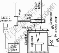
Fig.1 Schematic diagram of experimental setup
2.2 Experimental process
In the experiment, the substrate was fixed on the reaction chamber and the focusing lens was fixed on the stage that could be moved parallelly to the direction of induced light. After the chamber was evacuated by the vacuum pump, the work gas was input to the prescribed pressure, the laser beam was focused on the surface of substrate through the window. When the temperature in the irradiated area reached the level, at which the work gas could be decomposed, the deposition was shaped and grew along the irradiate direction to fabricate the microcarbon pillar[6-8].
We used two methods to get the microcarbon pillar. One was the fixed focus method, in this way, the growth of the microcarbon would stop when the point of deposition was off the focus region resulted in the temperature descend. This method could only get the shorter carbon pillar length. The other was moving focus mode that could acquire a longer carbon pillar by moving the focus along the direction of growth of carbon pillar with the speed near the growth rate. In this experiment, laser power and gas pressure were changed from 0.5 W to 4.5 W and from 225��133.3 Pa to 680��133.3 Pa, respectively. The diameter and length of various carbon pillars were measured, the averaged growth rate was calculated and the influences of various factors on diameter and growth rate were discussed.
3 Results and discussion
3.1 Diameter of microcarbon pillar
We made the experiments under various parameters to evaluate the influences of the laser power and work gas pressures on the diameter of microcarbon pillar that was fabricated by LCVD at the fixed focus method. The relationship between the diameter and the laser power was shown in Fig.2 and the relationship between the diameter and the pressure of source gas is shown in Fig.3.
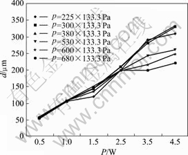
Fig.2 Relationship between diameter and laser power
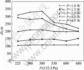
Fig.3 Relationship between diameter and pressure of source gas
The results of the experiment showed that as the laser power was increased, the diameter of the carbon pillar was augmented, and the variety regulation between diameter and power was almost linear. In the aspects of the gas pressure influence, the diameter of the carbon pillar was almost independent of gas pressure when the laser power was lower (��2.5 W). However, if the laser power was increased over 2.5 W and the gas pressure was above 400��133.3 Pa, the diameter of the carbon pillar would have a descent to a certain degree. It was understood that the temperature in focusing area increased as the laser power was increased and the decomposition of work gas became easy. When the gas pressure was at high level, the quick increase in the growth speed of the carbon resulted in that the deposition speed in the length direction was much faster than that in the diameter direction, so the diameter of the carbon pillar became small. In this experiment, the largest diameter of carbon pillar (about 330 ��m) was obtained at 4.5 W and 380��133.3 Pa but not at the highest pressure level of 680��133.3 Pa, so we thought that the diameter of carbon pillar was also affected by growth speed[9-11].
3.2 Length and averaged growth rate of carbon pillar
The effects of laser power on length and gas pressure on averaged growth rate of micro carbon pillar are shown in Figs. 4 and 5, Those experiment data were obtained in the range of laser power from 0.5 W to 4.5 W and the work gas pressure from 225��133.3 Pa to 680��133.3 Pa for 60 s of irradiation time. At the fixed focus mode, even if increasing irradiation time, the length of micro carbon pillar was still less than 4 mm. The length and averaged growth rate (the length of carbon pillar divided the growth time) were affected by the laser power and gas pressure almost linearly. The higher the laser power, the longer the length of carbon pillar and the higher the averaged growth rate too[12].
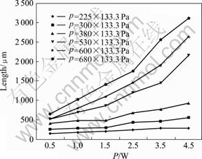
Fig.4 Effect of laser power on length
The influences of gas pressure on length and averaged growth rate could be divided into two phases. At the low level under 380��133.3 Pa of the gas pressure, the growth height and the growth rate of the carbon pillar had only a small increase when the laser power changed from 0.5 W to 4.5 W. However, if the gas pressure was above 380��133.3 Pa, the growth height and averaged growth rate of carbon pillar markedly rose as the laser power was increased. However, as soon as over the pressure point of 380��133.3 Pa, the averaged growth rate increased suddenly when the laser power was above
4.0 W. So the pressure about 400��133.3 Pa was considered as a boundary of growth rate rapidly increasing, this tallied with the case of diameter variety. In this experiment, at the parameters of 4.5 W of laser power, the
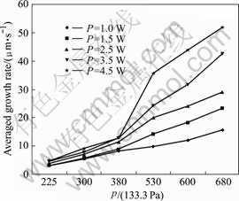
Fig.5 Effect of gas pressure on averaged growth rate
gas pressure of 680��133.3 Pa and irradiation time of 60 s, averaged growth rate of about 51 ��m/s could be obtained.
During the carbon pillar growing, the growth rate was asymmetric in each time segment, the growth speed of carbon pillar was the highest in initial 30 s and then gradually reduced to a jarless value. It was validated by the experiment using various parameters at both fixed focus mode and moving focus mode. In the moving focus mode, the averaged growth rate of carbon pillar was slightly higher than that in the fixed focus mode under the same parameter term, where the micro carbon pillar was fabricated at the growth rate around the focus moving speed. The relationship between averaged growth rate and irradiation time is shown in Fig.6.
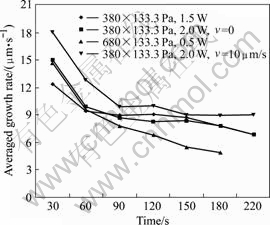
Fig.6 Averaged growth rate with respect to irradiation time
Using a moving focus method, we could fabricate a much longer microcarbon with a high aspect ratio. The important point was that the moving speed of focus must be near the growth rate of the carbon fabricated at various parameters. In Fig.7, the curves that are drawn according to the experimental data at 1.5 W and 2.0 W of laser power, 400��133.3 Pa and 380��133.3 Pa of gas pressure, respectively, show that the growth rate of carbon occurs a peak value at a certain moving speed of the focus. If the moving speed of the focus is apart from the peak value, the growth rate will fall rapidly and the growth of the carbon pillar will stop[13-14]. Based on the experimental data, some longer microcarbon pillars were fabricated at the moving focus method, as shown in Fig.8. The fabrication condition and parameters of the carbon pillar are listed in Table 1.
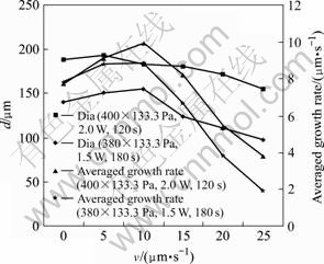
Fig.7 Averaged growth rate with respect to moving speed of focus
Table 1 Data of carbon pillars in Fig.8
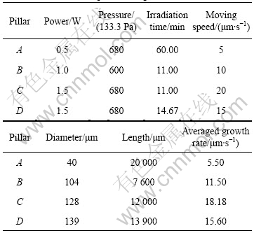
In the experiment, if the irradiation is not terminated factitiously the growth of microcarbon pillar will keep it up to a longer length. The micro carbon pillar fabricated by this method has good uniformity for diameter, for example, pillar A in Fig.8, its length reaches 2��104 ��m, but its diameter is around 44 ��m.
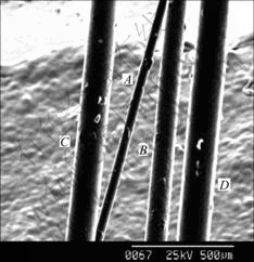
Fig.8 SEM image of deposits
3.3 Component, density and surface of micro carbon pillar
To evaluate the component of deposit, Raman spectroscopy was made for the carbon pillars fabricated by laser-induced CVD at various parameters. The results that are shown in Fig.9 indicate that there are two peaks for all samples at about 1 358 cm-1 and 1 600 cm-1 conformably. So we know that the deposits are graphite and the growth rate has nothing to do with the component of deposits[15].
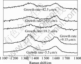
Fig.9 Raman spectra of deposits at various growth rates
The mass and size of carbon pillars were measured (the carbon pillar was regarded as a cylinder approximatively) and the density was calculated. The relationship of density and growth rate is shown in Fig.10. The density decreases with the growth rate increasing. The higher the power and pressure are, the higher the growth rate and the bigger the grain of deposits. As shown in Fig. 11, the averaged growth rates of pillars are 15.5, 30 and 51 ��m/s, respectively, and their surfaces are obviously different on roughness with the change of the averaged growth rate.
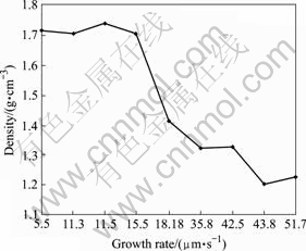
Fig.10 Density with respect to growth rate
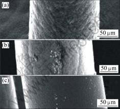
Fig.11 SEM images of microcarbon pillar at various growth rate: (a) 15.11 ��m/s; (b) 30 ��m/s; (c) 51 ��m/s
4 Conclusions
A microstructure of carbon could be fabricated by laser-induced chemical vapor deposition. The diameter of deposits augments almost linearly with laser power, which is increased and fackly independent of the pressure of work gas. The averaged growth rate of micro carbon is affected by laser power and the pressure of work gas jointly and it increases rapidly when the gas pressure reaches about 400��133.3 Pa and the laser power is above 4.0 W. As the averaged growth rate rises, the density of carbon pillar decreases and the surface of carbon pillar becomes even. The longer microcarbon pillar can be fabricated by controlling accurately the movement of focus and irradiation time. In further research, we presume upon to obtain the difform microcarbon pillar and spatial microcarbon structure[16-17].
References
[1] KIM J B, HAN S I, LEE S K, et al. Laser-induced chemical vapor deposition for the fabrication of micro carbon rods by pyrolytic decomposition of Ethylene [J]. Micro Ffabrication and Manipulation, 2002, (2): 431-434.
[2] MATSUI S, KAITO T, FUJITA J, et al. Tree-dimensional nanostructure fabrication by focused-ion-beam chemical vapor deposition [J]. Vac Sic Technol, 2002, 18(6): 3181-3186.
[3] FUJITA J, ISHIDA M, SAKAMOTO T, et al. Observation and characteristics of mechanical vibration in three-dimensional nanostructures and pillars grown by focused ion beam chemical vapor deposition [J]. Vac Sic Technol, 2001, 19(6): 2834-2837.
[4] OLIVEIRA J C, CONDE O. Deposition of boron carbide by laser CVD: a comparison with thermodynamic predictions [J]. Thin Solid Films, 1997, 307: 29-34.
[5] ZHOU Jian, LI Li-jun, CAO Zhi-qiang. CrWMn steel transformation hardening and toughing treatment by broadband-laser [J]. Heat Treatment of Metals, 2008, (4): 56-59.
[6] ONISCHUK A A, PANFULOV V N. Mechanism of thermal decomposition of silanes[J]. Russian Chemical Review, 2001, 70(4): 321-332.
[7] CAUSAAT B, HEMATI M, COUDERC J P. Silicon deposition from silane or disilane in a fluidized bed (part ��): Experimental study [J]. Chemical Engineering Science, 1995, 50(22): 3615-3624.
[8] CAUSAAT B, HEMATI M, COUDERC J P. Silicon deposition from silane or disilane in a fluidized bed (part ��): Theoretical analysis and modeling [J]. Chemical Engineering Science, 1995, 50(22): 3625-3635.
[9] QI Liu, SUSAN M. A new synthesis route for hydrogen terminated silicon nano-particles [J]. Materials Science and Engineering, 2002, B96: 72-75.
[10] ZHU Xiu-hong, CHEN Guang-hua, ZHANG Wen-li. Study on stability of hydrogenated amorphous silicon films [J]. Chinese Physics, 2005, 14 (11): 2348-2351.
[11] LEI Qing-song, WU Zhi-meng, GENG Xin-hua. Influence of the deposition parameters on the transition region of hydrogenated silicon films growth [J]. Chinese Physics, 2005, 14(11): 2342-2347.
[12] MCCORD P, YAU S L, BARD A J. Chemiluminescence of anodized and etched silicon: Evidence for a luminescent siloxene like layer on porous silicon [J]. Science, 1992, 257 (3): 68-69.
[13] MIKULEC F V, KIRTLAND J D, SAILOR M J. Ex-plosive nano-crystalline porous silicon and its use in atomic emission spectroscopy [J]. Advanced Materials, 2002, 14(1): 38-41.
[14] KOVALEV D V. Strong explosive interaction of hydrogenated porous silicon with oxygen at cryogenic temperatures [J]. Physical Review Letters, 2001, 87 (6): 683011-683014.
[15] NAKASO K, HAN B, AHN K H, et al. Synthesis of non-agglomerated nanoparticles by an electrospray assisted chemical vapor deposition (ES-CVD) method [J]. Journal of Aerosol Science, 2003, 34: 869-881.
[16] OKUR S, GONES M, FINGER F, et al. Diffusion length measurements of microcrystalline silicon thin films prepared by hot-wire/catalytic chemical vapor deposition (HWCVD) [J]. Thin Solid Films, 2006, 501: 137-140.
[17] DING Yi, LIU Guo-han, CHEN Guang-hua, et al. Semi-quantitative study on the Staebler-Wronski effect of hydrogenated amorphous silicon films prepared with HW-ECR-CVD system [J]. Chinese Physics, 2006, 15 (4): 813-817.
Foundation item: Project supported by Scientific Research Fund of Centre South University of Forestry and Technology; Project supported by Teaching Innovation Fund of Centre South University of Forestry and Technology
Received date: 2008-06-25; Accepted date: 2008-08-05
Corresponding author: ZHOU Jian, Associate professor; Tel: +86-13975894394; E-mail: zhoujian1134@163.com.
