

J. Cent. South Univ. (2018) 25: 2093-2106
DOI: https://doi.org/10.1007/s11771-018-3899-0

Stress redistribution of simply supported reinforced concrete beams under fire conditions
DING Fa-xing(������)1, LI Zhe(�)1, CHENG Shan-shan2, YU Zhi-wu(��־��)1, 3
1. School of Civil Engineering, Central South University, Changsha 410075, China;
2. School of Engineering, Plymouth University, PL4 8AA, United Kingdom;
3. National Engineering Laboratory for High Speed Railway Construction, Changsha 410075, China
 Central South University Press and Springer-Verlag GmbH Germany, part of Springer Nature 2018
Abstract:
This study presents experimental and numerical investigations of simply supported steel reinforced concrete (RC) beams under fire. The temperature field of cross sections, the vertical deflection at mid-span, and specifically the axial expansion displacement at beam-ends were measured during the fire tests. A novel finite element (FE) model of a RC beam under fire was developed, in which the water loss in the heat transfer analysis and the concrete transient strain in the mechanical analysis were considered. Based on the validated FE model proposed in this study, parametric studies were conducted to investigate the effects of the beam type, the protective layer thickness, and the load ratio on the thermal and mechanical behavior of simply supported RC beams. It was found that greater fire resistance and fire performance of girder beams in comparison to secondary beams contributed to the non-structural reinforcements, which effectively compensated for the reduced tensile capacities of structural reinforcements because of the degradation of the material properties. In addition, the history of normal stress distributions of concrete under fire can be divided into three phases: expansion, stress redistribution and plateau phases.
Key words:
Cite this article as:
DING Fa-xing, LI Zhe, CHENG Shan-shan, YU Zhi-wu. Stress redistribution of simply supported reinforced concrete beams under fire conditions [J]. Journal of Central South University, 2018, 25(9): 2093�C2106.
DOI:https://dx.doi.org/https://doi.org/10.1007/s11771-018-3899-01 Introduction
Reinforced concrete (RC) beams are commonly used in buildings, bridges and other structures because of several inherent advantages, such as good weather resistance and durability. However, high temperatures because of fire will considerably degrade the mechanical properties of concrete and steel reinforcements and result in a decrease in load capacity and an increase in the deformation of RC beams. Therefore, it is essential to fully understand the thermal and mechanical performance of RC beams under fire.
Over the past decades, numerous studies on the mechanical behavior and the fire resistance of RC beams under fire have been reported based on self-developed computer programs or finite element (FE) analyses [1�C12], where studies on the mechanical behavior of simply supported RC beams were conducted by BRATINA et al [2], CHOI et al [3], GAO et al [4, 5], LIMIN et al [6], and DWAIKAT et al [7]. RAFI et al [8, 9] proposed a three-dimensional finite element (FE) model for the prediction of structural responses of a simply supported RC beam at elevated temperatures, in which crack formation and propagation were modeled with the help of smeared cracks, and the effects of tension softening and stiffening were considered. A number of scholars, including GAO et al [4, 5], DWAIKAT et al [7, 10], ALBRIFKANI et al [11], and RUZIC et al [12], also focused on single-span RC beams with end restraints and reported that the axial restraints contributed to the improvement of structural fire performance. Studies on the mechanical behavior of continuous RC beams have been conducted, of which the most significant were the fire tests by SHI et al [13] and the FE analysis by XU et al [14] using ABAQUS commercial software.
The mid-span deflection and fire resistance of RC beams were investigated in the abovementioned studies. However, analysis on the stress redistribution within cross sections, that results from the different degradation of material properties at different cross-sectional heights because of temperature gradients, is not yet fully understood. Although the experimental results indicated that the fire performance of girder beams (with greater cross-sectional dimensions) is better than that of secondary beams (with smaller cross-sectional dimensions), further investigations are required for a better understanding. Therefore, this study aims to provide a better understanding of the stress redistribution phenomena within cross sections of RC beams at elevated temperatures through experimental and numerical approaches.
2 Finite element analysis
The thermo-mechanical analysis is performed in two separate steps: a heat transfer analysis, and a three-dimensional model is developed to conduct a mechanical analysis. The FE model is developed using the ABAQUS/Standard 6.10 commercial software [15].
2.1 Basic assumption
The following assumptions are made in the FE model:
1) The heat transfer and mechanical analysis are independent and uncoupled;
2) The temperature of the air inside the electric resistance furnace is uniform;
3) The specific heat of concrete is increased by 30% given the influence of concrete cracking on temperature distribution;
4) There is no slippage between the steel reinforcement and the concrete;
5) Concrete spalling is not considered in the numerical analysis.
2.2 Heat transfer analysis
2.2.1 Thermal properties of concrete
The conductivity (kc, W/(m����C)) of concrete given by LIE [16] is adopted in this study as follows:
 (1)
(1)
The specific heat (kJ/(kg����C)) of concrete specified in Eurocode 2 [17] is referred to in this study, and the formula is as follows:
 ,
,
 (2)
(2)
The concrete specific heat calculated in Eq. (2) is increased by 30% in order to consider the effect of water loss on the temperature distribution along the height of the cross sections, and is verified by comparing it with the test results in the following section.
The density of concrete (��c) is taken as a constant value of 2300 kg/m3 in the numerical model analysis [4]. The effects of water loss in concrete under heating is implicitly considered simultaneously by introducing the abovementioned amplified coefficient for concrete specific heat.
2.2.2 Thermal properties of reinforcement
The density (��s) of the reinforcement is taken as 7800 kg/m3 [4]. The conductivity (ks, W/(m����C)) of the reinforcement given in Ref. [16] is adopted, and is expressed as follows:
 (3)
(3)
The specific heat (kJ/(kg����C)) of the reinforcement given by LI et al [18] is adopted in this study:
 (4)
(4)
2.2.3 Numerical modeling
The 8-node heat transfer brick element DC3D8 is used for the concrete, and the 2-node heat transfer link element DC1D2 is used for the reinforcements. The structural division technique is adopted in the mesh generation. The tie constraint is applied on nodes to bond the concrete with the reinforcement. The radiative emissivity and integrated heat transfer coefficient on the exposed surface are set as 0.5 and 25 W/(m2����C), respectively [19]. The top surface of the beam is exposed to ambient temperature, therefore, the total heat transfer coefficient is taken as 9 W/(m2����C) [14]. The initial temperature of the model is defined as 20 ��C. The node temperatures are recorded at each time interval, and will be used in the mechanical analysis.
2.3 Mechanical analysis
2.3.1 Thermo-mechanical constitutive model of concrete
The creep and transient strains of concrete play a critical role in predicting the fire behavior of RC beams, particularly on the deflection and the rate of deflection [10]. Therefore, the influence of the concrete transient strains on the fire performance of RC beams is verified through an end-fixed concrete prism under exposure to fire.
The total strain of concrete under high temperature is considered as the sum of four different strain components: mechanical strain, thermal strain, transient strain, and creep strain [20]. The constitutive model of concrete under high temperature can be expressed as follows:
 (5)
(5)
where ��c,total is the total strain of concrete under high temperature; ��c,��, ��c,th, ��c,tr and ��c,cr are the mechanical strain, thermal strain, transient strain, and creep strain of concrete, respectively.
1) Mechanical strain
The non-linear damaged plasticity constitutive model for concrete is used, and the model under uniaxial compression at high temperature is as follows [21]:
 (6)
(6)
where y (= ��c/fcT) and x (= ��c/��cT) are the normalized stress and strain ratios of concrete to the uniaxial compressive concrete at high temperatures, respectively; ��c and ��c are the stress and strain of concrete, respectively; fcT is the uniaxial compressive strength of concrete at high temperature; and ��cT is the strain corresponding to the uniaxial compressive peak stress of concrete at high temperature. The parameters k1, m1 and ��1 are adopted to describe the ascending and descending phases of the stress�Cstrain relationship, and are taken as k1=9.1fcu�C4/9, m1=1.6(k1�C1)2, and ��1=2.5fcu3�� 10�C5, where fcu is the compressive strength of concrete cubes. The values of the elastic modulus and axial compressive strength of concrete are given in Ref. [21].
The constitutive model of concrete under uniaxial tension at high temperature is as follows [21]:
 (7)
(7)
where y (= ��c/ftT) and x (= ��c/��tT) are the normalized stress and strain ratios of concrete to the uniaxial tensile concrete at high temperature, respectively; ftT is the uniaxial tensile strength of concrete at high temperature; and ��tT is the uniaxial tensile peak strain of concrete at high temperature. The parameters k2, m2 and ��2 are adopted to describe the ascending and descending phase of the stress�Cstrain relationship, and are taken as k2=1.306, m2=5(k2�C1)2/3=0.15, and ��2=0.8. Given the beneficial effect of tensile reinforcements on increasing stress of concrete in an FE analysis, the value of ��2 is taken as 0.8. The values of the axial tensile strength and uniaxial tensile peak strain of concrete at high temperatures are given in Ref. [21].
2) Thermal strain
The thermal expansion coefficient of concrete is given in Ref. [16]:
 (8)
(8)
3) Creep strain
The creep strain of concrete proposed by GUO et al [22] is applied, and is as follows:
 (9)
(9)
4) Transient strain
The transient strain of concrete presented by GUO et al [22] is adopted as follows:
 (10)
(10)
GUO et al [22] tested a concrete prism under high temperatures that was axially loaded and restrained at two ends to prevent axial deformation during the entire heating process. It can be seen from Figure 1 that the computed results considering transient strain of concrete are in better agreement with the test data than those not considering transient strain. Therefore, the thermo-mechanical model applied in this study is reliable for predicting concrete transient strain.

Figure 1 Comparison of influence of concrete transient strain (Note: fc is the axially compressive strength of concrete at ambient temperatures)
2.3.2 Thermo-mechanical constitutive model of steel reinforcement
The total strain of steel reinforcement under high temperature is considered as the sum of three different strain components: mechanical strain, thermal strain, and high-temperature creep strain. The thermo-mechanical constitutive model of steel reinforcement under high temperatures can be expressed as follows:
 (11)
(11)
where ��s,total is the total strain of steel reinforcement under high temperature, ��s,��, ��s,th and ��s,cr are the mechanical, thermal, and high temperature creep strains of steel, respectively.
1) Mechanical strain
The constitutive model of steel reinforcement under high temperatures proposed by LIE [16] is as follows:
 (12)
(12)
where ��s is the stress of the steel reinforcement; and ��p=4��10�C6 fs, where fs is the yield strength of the steel reinforcement at ambient temperature. Expressions for the other parameters are as follows:

 (13)
(13)

 (14)
(14)
2) Thermal strain
The expression of thermal expansion coefficient (m/(m����C)) for steel reinforcement is given [16]:
 (15)
(15)
3) High temperature creep strain
The formula for high-temperature creep strain for steel reinforcements proposed by SUN et al [23] is adopted in the this study. The variation of high-temperature creep strain as a function of stress and temperature follows the strain-hardening rule. The expression is as follows:
 (16)
(16)
where a=�C8477, b=4.50, c=3060, d=0.228, e=0.002, and f=�C1.1 are coefficients for determining the high-temperature creep strain; and tf is the fire time in minute.
2.3.3 Numerical modeling
To avoid local stress concentration at supports and loading positions, cushion blocks were manufactured and connected to the simply supported beam with tie constraints. Steel reinforcements were embedded in the concrete to eliminate slippage. The FE mesh of the RC beams, identical in both the mechanical and the heat transfer analyses, are shown in Figure 2. However, different element types were defined in the mechanical analysis. The 8-node brick element C3D8 was used for the concrete and cushion blocks, with three translation degrees-of-freedom at each node. The 2-node truss element T3D2, that could only support axial forces and plastic deformations, was used to model the steel reinforcement. An implicit analysis was selected for solving the model.

Figure 2 Mesh generation of analysis model
3 Experimental investigation
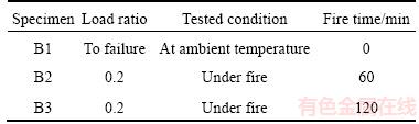
3.1 Test specimens
Three simply supported RC beams were designed and tested in this study. The nominal dimensions of each specimen were 3800 (L) mm�� 200 (b) mm��300 (h) mm, where L is the effective span of a tested beam, b is the width of the cross section, and h is the height of the cross section. The detailed geometry and arrangement of the reinforcements are shown in Figure 3. Among the specimens, B1 was tested at ambient temperature to obtain the ultimate capacity. The cracking load and ultimate capacity of beam B1 were 24 and 70 kN, respectively. Two-point concentrated loads of 14 kN, that was 20% of the ultimate bearing capacity, were applied to beams B2 and B3 before heating to simulate the normal service conditions. The tested specimens are secondary beams (with relatively small dimensions), with small load ratios. Therefore, a load ratio of 0.2 was adopted in this study, it was taken as the minimum recommended load ratio (0.2�C0.8).
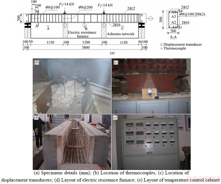
Figure 3 Specimen details and test setup:
Table 1 Test program for RC beams
3.2 Material properties
The concrete was made from ordinary Portland cement. The mix proportions of concrete by relative mass are presented in Table 2. The compressive strengths of the concrete cube coupons of B1, B2 and B3 are 37.7, 36.3 and 33.2 MPa, respectively. The mechanical properties of the reinforcements at ambient temperature are presented in Table 3.
Table 2 Mix mass proportion of concrete

Table 3 Mechanical properties of reinforcement at ambient temperature

3.3 Instrumentation
The fire tests on the RC beams were conducted using the horizontal electric resistance furnace self- designed at Central South University, China. The test furnace comprised three fire chamber segments, with dimensions of 3700 (l) mm��1000 (b) mm��800 (h) mm. Three thermocouples were distributed throughout the test chamber to monitor the furnace temperature during a fire test to maintain a constant temperature along the beam span. During the fire test, the furnace temperature could be automatically adjusted by controlling the electric current and power. The test setup and locations of the thermocouples are shown in Figure 3.
3.4 Temperature measurement
Because of the limitations of the actual power capacity of the fire furnace, there were differences between the actual temperature and that recommended by the ISO-834 (1999) [24] fire curve (see Figure 4). The actual curve can be extracted into the following formula:
 (17)
(17)
where T0 is the initial temperature of the fire furnace; T is the average temperature of the three measured points; and tf is the fire time (min).
As can be seen in Figure 4, the temperature curves at each measured point were similar, that is, in agreement with the former assumption that the temperature along the beam span is uniform. The temperature field of a three-side-fired RC beam, therefore, could be represented by a 2-dimensional temperature distribution within the cross-section and a uniform temperature distribution in the longitudinal direction. The temperatures of the concrete at different positions were measured by standard thermocouples embedded in specimens throughout the fire test.

Figure 4 Temperature (T)�Cfire time (tf) curves for measured fire scenarios
3.5 Test observations
In the process of heating up, water vapor was seen to escape from the exposed surface at approximately 15 min, and then from the top surface. The bulk of the top surface was covered by water vapor after 45 min. After heating for 30 min, the rate of increase in the temperatures and mid-span deflections of the two specimens at the measured points decreased. However, after heating for 70 min, a rapid increase was observed in the temperatures and mid-span deflections, accompanied by evaporation from the top surface. The mid-span deflection of beam B3 approached 100 mm after 120 min.
4 Verification of FE model
In this section, the numerical model is verified by comparing the predictions of the FE model with test data from this study and DWAIKAT et al [7]. The properties of tested beam B1 from DWAIKAT et al [7] are shown in Figure 5.
4.1 Thermal response
Figure 6 shows the comparison of temperatures in reinforcements and two concrete locations (TC10 and TC11 in Figure 5) for beam B1 exposed to an ASTM E119 (2001) [25] standard fire. It can be seen that the calculated curves are in good agreement with the tested data. In addition, the calculated temperatures from the FE model, in which the 30% increase in the concrete specific heat calculated from Eq. (2) is introduced in the heat transfer analysis model in order to consider the influence of water loss on temperature distribution, are significantly closer to the test results than those not increased. Figure 7 shows the comparison of temperatures in three concrete locations (A1, A2 and A3 in Figure 3(a)) for beam B2 exposed to the practical fire of Eq. (17). In general, the experimental and calculated temperatures were in good agreement.
4.2 Mechanical response
Figure 8 shows the comparison of load- deflection curves at one of the loading points between the FE model and the tested results. It can be seen that they are in good agreement, indicating that the damaged plasticity constitutive model of concrete at ambient condition introduced in this study is also reliable.
The FE model was verified by comparing the numerical results from the FE model with the tested and predicted deflections at mid-span for beam B1 from DWAIKAT et al [7] in Figure 9. The FE model became invalid when the fire time reached 180 min because of convergence issues, as can be seen in the fire resistance of analyzed beam B1. Good agreement was found between the calculated and the tested results throughout the fire exposure time.
Figure 10 shows plots of the tested and calculated deflections for beams B2 and B3 in this study. It can be seen that the calculated curves are in good agreement with the tested data, indicating that the constitutive models of reinforcement and concrete at elevated temperatures adopted in this study are reasonable.
5 Parametric analysis
The thermal and mechanical behavior of simply supported RC beams subjected to a standard fire in accordance with ISO-834 (1999) were investigated with respect to three critical parameters: beam type, protective layer thickness (c), and load ratio (m), that is defined as the load applied on the specimen to the ultimate capacity of the specimen at ambient temperature.
5.1 Beam type
In general, there is no clear definition between the girder and secondary beams. Qualitatively, the primary differences between the two beam types are the sectional dimensions and the non-structural reinforcement. Girder beams typically have greater sectional dimensions and are typically laid with non-structural reinforcements. The aim of this parametric study is to better understand the stress redistribution within the cross-section of a girder beam, considering the effect of non-structural reinforcements. A series of FE analyses were conducted for secondary and girder beams with the same protective layer thicknesses (c=25 mm) and load ratios (m=0.4) in order to investigate the differences in stress redistributions between the two beam types.
The properties of secondary RC beams are identical to the tested specimens with depth-to-span ratio of 0.08. The tested ultimate bearing capacity of the secondary beam, with c=25 mm and at ambient temperature, was 70 kN. The characteristic strengths of materials are adopted in the parametric analysis. The strength of the stirrups and reinforcements are taken as 300 and 400 MPa, respectively. The effective span of girder beams with the depth-to-span ratios of 0.1, that is marginally greater than that of the secondary beams, is 7.2 m. Cross sections of the secondary and girder beams with c=25 mm are shown in Figure 11. The expected ultimate bearing capacity of the girder beam, with c=25 mm and at ambient temperature, is 255 kN. All analyzed beams were exposed to fire for 120 min, that is the designed first-grade fire resistance prescribed in GB T9978.1�C2008 [26].
Figure 5 Properties of tested beam B1 from DWAIKAT (Unit: mm)

Figure 6 Comparison between measured and calculated temperature (T)�Cfire time (tf) curves for beam B1 from DWAIKAT

Figure 7 Comparison between measured and calculated temperature (T)�Cfire time (tf) curves for specimen B2
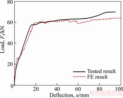
Figure 8 Comparison between measured and calculated load (Ff)�Cmid-span deflection (u) curves for specimen B1
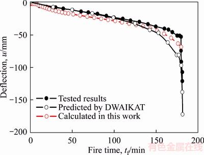
Figure 9 Comparison of deflection (u)�Cfire time (tf) curves between FE-calculated results with tested and predicted results for beam B1 from DWAIKAT
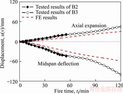
Figure 10 Measured and calculated axial expansions (v) and mid-span deflections (u) as a function of fire time (tf) for beams B2 and B3
A comparison of the calculated temperatures of reinforcements as a function of fire time for the secondary and girder beams is shown in Figure 12. With an increased sectional area 1.73 times that of the girder beam compared to the secondary one, the temperatures of reinforcement S1 and S4 decreased by 9% and 7%, respectively, at an exposure time of 120 min. It can be concluded that the rate of increase in reinforcement temperatures decreased because of the significant heat absorption capacity of concrete.
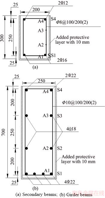
Figure 11 Cross sections of analyzed beams with c=25 mm and variation method of c:(Unit: mm)

Figure 12 Calculated temperatures (T) of reinforcements as a function of fire time (tf) for secondary and girder beams
As can be seen in Figure 13, the bottom tensile reinforcement (S1) yielded (before 10 min) earlier than the top compressive reinforcement (S4)(approximately 18 min) for secondary beams. During the entire heating process, the neutral axis of the cross section shifted upward for the secondary beams because of concrete cracking. The sectional compressive force, that was originally sustained by both the top reinforcements (S4) and the concrete in the compression zone, is borne solely by the compressive concrete when the top reinforcements (S4) yielded (between 18�C55 min). At this stage, the height of the compressive concrete had decreased significantly, that is identical to the typical stress contour of concrete, as can be seen in Figure 14, where the gray area indicates concrete in tension. This explains why the ultimate capacity for a secondary beam decreased significantly and the mid-span deflection increased significantly.
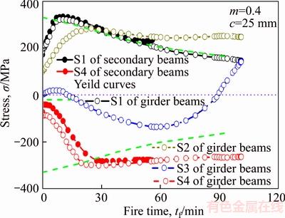
Figure 13 Calculated stress (��) of reinforcements as a function of fire time (tf) for secondary and girder beams
For girder beams, as can be seen in Figure 13, the tensile stresses of the bottom non-structural reinforcements (S2) apparently increase with increasing fire exposure time, specifically after the bottom tensile reinforcements (S1) yielded (at 10 min). Therefore, the tensile force in a girder beam is sustained by both the bottom tensile reinforcements (S1) and the non-structural reinforcements (S2), that efficiently delays the cracking of concrete in the tension zone and the upward shift of the neutral axis of the cross section. Similarly, the compressive stress at the top non-structural reinforcements (S3) apparently increases over the fire exposure time, specifically after the top compressive reinforcements (S4) yielded (at 26 min). At this point, although the material properties of the bottom tensile reinforcements degrade over fire time, this decreased tensile force is effectively compensated for by the non-structural reinforcements, that results in minor changes in the neutral axis depth and little significant reduction in compressive concrete depth. This is identical to the normal stress contour of concrete, as seen in Figure 15. This is the reason that the ultimate capacity of a girder beam did not decrease significantly, and the mid-span deflection increased only marginally.

Figure 14 Distribution of concrete normal stress for secondary beam with c=25 mm and m=0.4:

Figure 15 Distribution of concrete normal stress for girder beam with c=25 mm and m=0.4:
In conclusion, the reasons why the stress redistribution within cross sections of girder beams under fire is more satisfactory than that of secondary beams are attributed to the following two factors:
1) The greater capacity of heat absorption of concrete for girder beams (with greater sectional dimensions) compared to secondary beams (with smaller sectional dimensions) can efficiently decrease the degradation of mechanical properties of materials.
2) For girder beams, the efficient support from the non-structural reinforcements leads to insignificant changes in the position of the neutral axis and the height of compressive concrete within a cross section when compared to secondary beams.
5.2 Protective layer thickness (c)
According to the requirements prescribed in the Chinese National Standard GB 50010�C2010 [27], the protective layer thickness should not be less than the nominal diameter of the reinforcements. The protective layer thickness for the secondary and girder beams adopted in these analyses are 25 and 35 mm, respectively. The variation of protective layer thicknesses is accomplished by making the concrete thicker on the fire sides (as seen in Figure 11) in order to keep the position of the reinforcements, effective height of the cross section, and the ultimate capacity of beams unchanged.
By using the FE model validated above, the temperatures of two reinforcement locations (S1 and S4 shown in Figures 3 and 11) for simply supported secondary and girder beams subjected to ISO-834 (1999) standard fire were analyzed, as shown in Figure 12. Using the girder beam as an example, in comparison with c=25 mm, the temperatures of reinforcements S1 and S4 for the c=35 mm beam decrease by 14%. Therefore, it is concluded that increasing the protective layer thickness can yield a decrease in temperatures in reinforcements.
The fire resistance of the analyzed beam corresponds to the time when the beam fails, if the beam deflection at mid-span is greater than L2/(400d) mm or the rate of deflection reaches L2/(9000d) mm/min and the max deflection exceeds L/30, where L is the effective span (mm), and d is the effective depth of cross section (mm) [25].
Curves of the calculated mid-span deflections as a function of fire time for analyzed secondary beams and girder beams, that are all exposed to the designed first-grade fire resistance of 120 min, are shown in Figures 16 and 17, respectively. Except for one secondary beam (with m=0.2 and c=35 mm) that did not fail until a fire time of 120 min, all the other beams failed because of deflection limits. However, neither the two girder beams with m=0.2, nor the one with m=0.4 and c=35 mm, failed before the fire time reached 120 min. All the girder beams failed because of the deflection failure criterion. The mid-span deflections in all analyzed beams attained the deflection criterion earlier than the deflection rate criterion. Fire resistances and failure modes of all analyzed beams are presented in Table 4. From a comparison of the fire resistance and failure modes between the secondary beams and girder beams with the same load ratio (m), it is concluded that increasing the protective layer thickness (c) can yield an improvement in mechanical behavior, such as fire resistance and deflection behavior, of both simply supported RC secondary and girder beams.

Figure 16 Calculated mid-span deflection (u) as a function of fire time (tf) for secondary beams with different m and c

Figure 17 Calculated mid-span deflection (u) as a function of fire time (tf) for girder beams with different m and c
Table 4 Fire resistances and failure modes of analyzed beams

5.3 Load ratio (m)
The load ratio (m) is defined as the load applied to the beam to the ultimate capacity at ambient temperature [14]:
 (18)
(18)
where Ff is the actual concentrated load applied to the beam; and Fu is the expected ultimate capacity of the beam at ambient temperature and calculated by the FE model.
The load ratios for both the secondary and girder beams adopted in these analyses are 0.2, 0.4, and 0.6. Figures 16 and 17 show the comparisons of the mid-span deflections versus fire time for simply supported secondary and girder RC beams with different load ratios. In comparison with the secondary beam, with c=35 mm and m=0.4, the fire resistance of the secondary beam, with m=0.6, decreases by 60% (from 75 min to 30 min), based on deflection criteria. Similar results have been observed for girder beams. It can be seen that the load ratio has an apparently significant influence on the mid-span deflection and fire resistance of RC beams. The greater the load ratio, the smaller the fire resistance, and the greater the rate of deflection increases.
5.4 Discussions
The curves of the development of the concrete stresses at chosen points in the mid-spans of the secondary and girder beams are shown in Figures 18 and 19, with the locations of A1�CA4 shown in Figure 11. The curves can be typically divided into three phases: expansion phase (AB), stress redistribution phase (BC), and plateau phase (CD). In the initial fire phase, the significant temperature gradients within a cross-section result in nonlinear thermal strains and flexural deformations, that are convex toward the high- temperature zone. Because of the restraint of the plain cross section, the thermal strain causes the upper concrete to be in tension and the bottom concrete to be in compression, that is contrary to in-service loads. With increased fire time, the mechanical properties of the materials at elevated temperatures degraded gradually from bottom to top, that leads to stress redistribution within the cross section. Finally, the normal stress of the concrete is in the short-plateau phase under the constant load, and the invariant temperature gradient is a result of small temperature increments in the later stages of the ISO-834 (1999) standard fire.
It can be seen from Figures 18 and 19 that the plateau phase (CD) of the normal stress curves is significantly longer for the girder beam than that for the secondary beam with the same protective layer thickness and load ratio. Therefore, the fire performance of the simply supported girder beams outperforms that of the secondary beams.
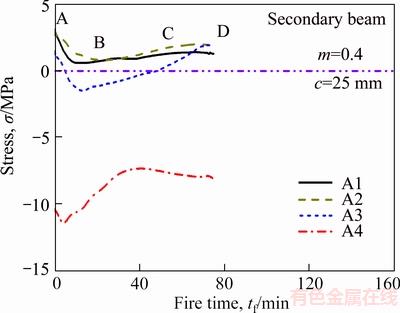
Figure 18 Development of concrete normal stresses (��) at chosen points in mid-span of secondary beam

Figure 19 Development of concrete normal stresses (��) at chosen points in mid-span of girder beam
6 Conclusions
This study presented a combined experimental and numerical study on the mechanical behaviors of simply supported RC beams exposed to fire. Parametric studies were also conducted in order to investigate the influence of three critical parameters on the thermal and mechanical behavior of the simply supported RC beams, i.e., the beam type (including secondary and girder beams), the protective layer thickness, and the load ratio. Based on the results, the following conclusions could be drawn:
1) An amplification factor of 1.3 is proposed for the concrete specific heat from Eurocode 2 in order to consider the effect of water loss under heating.
2) The concrete transient strain should be considered in predicting the fire behavior of RC beams in FE analyses using ABAQUS.
3) The primary reason for the greater fire resistance and better fire performance for girder beams in comparison to secondary beams is the contribution of non-structural reinforcements, that effectively compensates for the reduced tensile force of structural reinforcements resulting from degradation of the material properties.
4) With the increased protective layer thickness and the decreased of load ratio, the mechanical behavior under fire is considerably improved.
5) The history of normal stress distributions of concrete under ISO-834 fire heating can be divided into three phases: expansion, stress redistribution, and plateau phases.
References
[1] FITIANY S, YOUSSEF M. A simplified sectional analysis approach for RC elements during fire events [C]// Structures in Fire: Proceedings of the Sixth International Conference. East Lansing, United States, 2010: 239�C246. DOI: 10.13140/ 2.1.3180.8007.
[2] BRATINA S, SAJE M, PLANINC I. The effects of different strain contributions on the response of RC beams in fire [J]. Engineering Structures, 2007, 29(3): 418�C430. DOI: 10.1016/j.engstruct.2006.05.008.
[3] CHOI E G, SHIN Y S. The structural behavior and simplified thermal analysis of normal-strength and high-strength concrete beams under fire [J]. Engineering Structures, 2011, 33(4): 1123�C1132. DOI: 10.1016/j.engstruct.2010.12.030.
[4] GAO W Y, DAI J G, TENG J G, CHEN G M. Finite element modeling of reinforced concrete beams exposed to fire [J]. Engineering Structures, 2013, 52(9): 488�C501. DOI: 10.1016/j.engstruct.2013.03.017.
[5] GAO W Y, DAI J G, TENG J G. Fire resistance of RC beams under design fire exposure [J]. Magazine of Concrete Research, 2016, 69(8): 1�C22. DOI: 10.1680/jmacr. 15.00329.
[6] LIMIN L, YOMG Y, ROBBY C, LUC T. Influencing factors for fire performance of simply supported RC beams with implicit and explicit transient creep strain material models [J]. Fire Safety Journal, 2015, 73(1): 29�C36. DOI: 10.1016/ j.firesaf.2015.02.009.
[7] DWAIKAT M B, KODUR V K R. Response of restrained concrete beams under design fire exposure [J]. Journal of Structural Engineering, 2009, 135(11): 1408�C1417. DOI: 10.1061/(ASCE) ST.1943-541X.0000058.
[8] RAFI M M, NADJAI A, ALI F. Finite element modeling of carbon fiber-reinforced polymer reinforced concrete beams under elevated temperatures [J]. ACI Structural Journal, 2008, 105(6): 701�C710.
[9] RAFI M M, NADJAI A. Numerical modelling of carbon fibre-reinforced polymer and hybrid reinforced concrete beams in fire [J]. Fire and Materials, 2013, 33(5): 374�C390. DOI: 10.1002/fam.2135.
[10] DWAIKAT M B, KODUR V K R. A numerical approach for modeling the fire induced restraint effect in reinforced concrete beams [J]. Fire Safety Journal, 2008, 43(4): 291�C307. DOI: 10.1016/j.firesaf.2007.08.003.
[11] ALBRIFKANI S, WANG Y C. Explicit modelling of large deflection behaviour of restrained reinforced concrete beams in fire [J]. Engineering Structures, 2016, 121: 97�C119. DOI: 10.1016/j.engstruct.2016.04.032.
[12] RUZIC D, KOLSEK J, PLANINC I, SAJE M, HOZJAN T. Non-linear fire analysis of restrained curved RC beams [J]. Engineering Structures, 2015, 84: 130�C139. DOI: 10.1016/j.engstruct.2014.11.012.
[13] SHI Xu-dong, GUO Zhen-hai. Experimental investigation of behavior of reinforced concrete continuous beams at elevated temperature [J]. Civil Engineering Journal, 1997, 30: 26�C34. (in Chinese)
[14] XU Q F, HAN C Q, WANG Y C, LI X M, CHEN L Z, LIU Q. Experimental and numerical investigations of fire resistance of continuous high strength steel reinforced concrete T-beams [J]. Fire Safety Journal, 2015, 78(9): 142�C154. DOI: 10.1016/j.firesaf.2015.09.001.
[15] HIBBIT T, KARLSON S. ABAQUS version 6.10: ABAQUS user's manuals [M]. Hibbitt, Karlson: Sorenson Inc, 2010.
[16] LIE T T. Fire resistance of circular steel columns filled with bar-reinforced concrete [J]. Journal of Structural Engineering, 1994, 120(5): 1489�C1509. DOI: 10.1061/(ASCE) 0733-9445/ 94/0005-1489.
[17] Eurocode 2. Design of concrete structures, Part 1.1: General rules and rules for buildings [M]. Brussels, Belgium: European Committee for Standardization, 2004.
[18] LI Y Q, MA D Z, XU J. Fire design calculation and construction principle of building structure [M]. Beijing: China Architecture & Building Press, 1991. (in Chinese)
[19] Eurocode 1. Actions on structures, Part 1�C2: General actions- Actions on structures exposed to fire [M]. Brussels, Belgium: European Committee for Standardization, 2002.
[20] ANDERBERG Y, THELANDERSSON S. Stress and deformation characteristics of concrete at high temperatures, Part 2: Experimental investigation and material behavior model [M]. Bulletin: Bulletin of Division of Structural Mechanics & Concrete Construction, 1976.
[21] DING F X, YU Z W. Behavior of concrete and circular concrete-filled steel tube stub columns at high temperatures [J]. Journal of Central South University of Technology, 2006, 13(6): 726�C732. DOI: 10.1007/s11771-006-0022-8.
[22] GUO Z H, SHI X D. Experiment and calculation of reinforced concrete at elevated temperatures [M]. Beijing: Tsinghua University Press, 2011.
[23] SUN Jin-xiang, GAO Wei. Synthetic fire prevention design of building [M]. Tianjin: Tianjin Science & Technology Translation & Publishing Cooperation, 1994: 406�C411. (in Chinese)
[24] ISO 834-1. Fire resistance tests��Elements of building construction [S].
[25] ASTM E119-01. Standard methods of fire test of building construction and materials [S].
[26] GB T9978.1��2008. Fire-resistance tests-Elements of building construction [S]. (in Chinese)
[27] GB 50010��2010. Code for design of concrete structures [S]. (in Chinese)
(Edited by FANG Jing-hua)
���ĵ���
�������¸ֽ��������֧��Ӧ���طֲ��о�
ժҪ�����ĶԸֽ��������֧���Ŀ������ܽ��������о�����ֵ�������ڻ��������У����������¶ȷֲ��������ӶȺ��������ͽ��в��ԡ���������ˮ����ת�ƶԽ����¶ȷֲ��ͻ�����˲̬��Ӧ��Խṹ��������Ӱ��ĸֽ���������������ģ�͡����þ�������֤����������Ԫģ�ͣ����������͡��������Ⱥ������ر�������ҪӰ��������з�������������������������ͻ����ܼ��ͻ������ڴ�������Ҫԭ���������Ĺ���ֽ������Ч�ֲ������������ݽ�����������˻�����Ի���ȫ�����л�����Ӧ���طֲ����ɽ��л��ֲ�������
�ؼ��ʣ��ֽ����������˲̬��Ӧ�䣻���֣�����������Ӧ���طֲ�
Foundation item: Project(51578548) supported by the National Natural Science Foundation of China; Project(2018JJ3202) supported by the Natural Science Foundation of Hunan Province, China; Project(17C0681) supported by the Educational Departmental Science Research of Hunan Province, China
Received date: 2017-06-22; Accepted date: 2017-11-10
Corresponding author: LI Zhe, PhD Candidate; Tel: +86�C15873167874; E-mail: 09lizhe@163.com; ORCID: 0000-0003-0581-8699
Abstract: This study presents experimental and numerical investigations of simply supported steel reinforced concrete (RC) beams under fire. The temperature field of cross sections, the vertical deflection at mid-span, and specifically the axial expansion displacement at beam-ends were measured during the fire tests. A novel finite element (FE) model of a RC beam under fire was developed, in which the water loss in the heat transfer analysis and the concrete transient strain in the mechanical analysis were considered. Based on the validated FE model proposed in this study, parametric studies were conducted to investigate the effects of the beam type, the protective layer thickness, and the load ratio on the thermal and mechanical behavior of simply supported RC beams. It was found that greater fire resistance and fire performance of girder beams in comparison to secondary beams contributed to the non-structural reinforcements, which effectively compensated for the reduced tensile capacities of structural reinforcements because of the degradation of the material properties. In addition, the history of normal stress distributions of concrete under fire can be divided into three phases: expansion, stress redistribution and plateau phases.
[24] ISO 834-1. Fire resistance tests��Elements of building construction [S].
[25] ASTM E119-01. Standard methods of fire test of building construction and materials [S].
[26] GB T9978.1��2008. Fire-resistance tests-Elements of building construction [S]. (in Chinese)
[27] GB 50010��2010. Code for design of concrete structures [S]. (in Chinese)
