
J. Cent. South Univ. (2012) 19: 2541-2547
DOI: 10.1007/s11771-012-1308-7![]()
Novel Retinex algorithm by interpolation and adaptive noise suppression
LI Wu-jing(���侢)1, GU Bo(�Ų�)1, HUANG Jiang-tao(�ƽ���)2,3, WANG Ming-hui(������)1
1. College of Computer Science, Sichuan University, Chengdu 610065, China;
2. College of Computer and Information Engineering, Guangxi Teachers Education University, Nanning 530023, China;
3. Key Laboratory of Scientific Computing and Intelligent Information Processing of Guangxi Province, (Guangxi University), Nanning 530023, China;
? Central South University Press and Springer-Verlag Berlin Heidelberg 2012
Abstract:
In order to improve image quality, a novel Retinex algorithm for image enhancement was presented. Different from conventional algorithms, it was based on certain defined points containing the illumination information in the intensity image to estimate the illumination. After locating the points, the whole illumination image was computed by an interpolation technique. When attempting to recover the reflectance image, an adaptive method which can be considered as an optimization problem was employed to suppress noise in dark environments and keep details in other areas. For color images, it was taken in the band of each channel separately. Experimental results demonstrate that the proposed algorithm is superior to the traditional Retinex algorithms in image entropy.
Key words:
Retinex algorithm; illumination estimation; interpolation; adaptive noise suppression��
1 Introduction
Due to the limited dynamic ranges of common acquisition devices, low contrast images are often produced. Particularly, in high dynamic range environments, these images show over-exposed or under-exposed regions. People cannot easily distinguish details of background scene. Therefore, the enhancement problem should be addressed.
The Retinex theory is a classic model to solve the problem. Since it was conceived by Land and MCCANN [1], several algorithms, such as random walk algorithms [1-3], recursive algorithms [4-5], center/surround algorithms [6-8], and variational algorithms [9-10], were proposed on multiple interpretations.
The first version of Retinex developed by Land and MCCANN [1] is the random walk algorithm. ��Random walk�� means that the next pixel position is chosen randomly from the neighbors, and the lightness of each pixel depends upon the multiplication of radios along random walks. Based on previous work, two-dimensional pixel sprays were used [2]. The main drawbacks of random-walk algorithms are their high computational complexity and free implementation parameters, such as the number of paths and their lengths. Morel et al [3] proved that the Retinex solutions satisfy a discrete Poisson equation if the paths are assumed to be symmetric random walks, and implemented an exact and fast algorithm using only two fast Fourier transform algorithms. However, the local contrast adjustment is not enough.
Recursive algorithms were proposed by Frankle and McCann [4]. These algorithms compute long-distance iterations between pixels first and then progressively move to short-distance interactions. And the spacing between the pixels being compared decreases with each step until the spacing decreases to one pixel. At the same time, the direction between pixels changes at each step in clockwise order. The comparison is implemented using the ratio-product-reset-average operation at each step. To improve the efficiency, a multi-resolution version was proposed by Funt et al [5]. The main drawback is that the number of iterations is not defined and has a critical effect on the results.
Center/surround Retinex algorithms share the following basic motivation: The reflectance image corresponds to the sharp details in the image, whereas the illumination image is expected to be spatially smooth and reasonably supposed to be a low-pass version of the intensity image. To reduce halo artifacts, multi-scale Retinex with color restoration (MSRCR) was proposed by averaging multi single-scale Retinex using multi different spatial scales [6]. Recently, the Kernel-based Retinex (KBR) was proposed by Bertalmio et al [7], and the authors proved that Retinex and KBR share the same intrinsic properties. It was obtained by the computation of the expectation of a suitable random variable weighted with a kernel function. The KBR as Wilson-Cowan equation was implemented in Ref. [8]. Compared with random walk and recursive algorithms, center/surround Retinex algorithms are faster and the number of parameters is notably reduced. However, it is difficult to distinguish between edges and details (especially having large intensity differences) when estimating the illumination. Thus, halo artifacts usually arise in the presence of high-contrast edge.
The last interesting algorithms are based on the variational model for Retinex provided by Kimmel et al [9]. They found the similarities in the apparently different approaches, and summarized the possible assumptions about the illumination image. Adding these constraints allows their algorithm to converge to a unique solution, the optimal illumination, and a variational framework for Retinex that unifies the previous Retinex algorithms was developed. Based on the proposed variational model, the illumination estimation problem was formulated as a quadratic programming optimization problem. However, the computational complexity is high since the optimization requires a number of iterations. In Ref. [10], Elad implemented the Retinex by two bilateral filters: The first evaluates the illumination and the other is used for the computation of the reflectance. The algorithm can handle better edges, and suppress noise in dark areas. However, the details are blurred since the smoothness is not adaptive.
There are two common drawbacks of Retinex algorithms mentioned above: One is the possible apparition of halo artifacts because it is difficult to distinguish edges and details while estimating the illumination; the other is related to noise suppression. When attempting to amplify signals, noise is also amplified, especially in dark environments. At the same time, standard image denoising methods might over-blur objects which have high illumination, or insufficiently suppress noise in dark environments.
In this work, a novel Retinex algorithm was proposed to solve these problems. Contrasting with the previous algorithms, the illumination was estimated by an interpolation technique, and a weight related to the illumination was added in the regularization term to adaptively suppress noise in dark environments and keep details in other areas.
2 Retinex
The Retinex theory is an important image processing technique, which can effectively enhance contrast and compress high dynamic range. The basic principles of Retinex are: 1) The radios of intensities from neighboring locations are assumed to be illumination invariant; 2) Lightness in a given channel is computed over large regions based on combining evidence from local radio; 3) The location with the highest lightness in each channel is assumed to have 100% reflectance within the band of that channel [11].
The basic concept in the Retinex theory is to decompose a given intensity image I into two different images: The reflectance image R (intrinsic properties of the objects in the scene, and the range is 0��R��1), and the illumination image L (the rays projected from the light sources), such that, in the image domain, there is
I(p)= R(p)�� L(p) (1)
where p denotes the two-dimensional position.
After removing the effect of different illuminations, the reflectance image is obtained.
3 Retinex by interpolation and adaptive noise suppression
In this work, a new Retinex algorithm is achieved mainly by two steps. The first step is to estimate the illumination image, and the other is to compute the reflectance image with adaptive noise suppression. In the first step, the illumination estimation is based on the basic principle of the Retinex theory: The location with the highest lightness in each channel is assumed to have 100% reflectance within the band of that channel [11]. After locating these pixels, the illumination is obtained by an interpolation technique. In the second step, recovery is posed as an optimization problem, in which the reflectance image is regularized. The regularization operator is weighted in order to achieve dependency on object illumination and edges.
The flowchart is shown in Fig. 1. For color images, it is taken in the band of each channel separately.
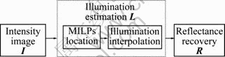
Fig. 1 Algorithm flowchart
3.1 Estimation of illumination
The proposed method for estimating the illumination is based on the basic principle of Retinex theory: The location with the highest lightness in each channel is assumed to have 100% reflectance within the band of that channel [11]. The illumination point (ILP) is defined as the pixel in the intensity image where the reflectance value is 100% (in the other words, an ILP is a pixel where the intensity value is equal to the illumination). However, there may not be any ILP in some regions. In this work, the ILP is replaced by the maxima illumination point (MILP), which is defined as the pixel in the intensity image where the reflectance value is the maximum in a region with the uniform illumination. After locating the MILPs, the whole illumination image is calculated by an interpolation technique.
1) MILPs location
Based on the definition of MILP, in a region with the uniform illumination, a MILP should be a maximum in the region of the intensity image. A simple location method is employed in this work, which is similar to the work in Ref. [12]. Pixel p is reported as a MILP if it has the greatest value in k��k neighborhood around p.
2) Interpolation of illumination image
After locating the MILPs, an interpolation technique proposed for image colorization [12-13] is employed to estimate the whole illumination image L from an intensity image I and a set of MILPs M.
Based on the assumption of spatial smoothness, the difference between the illumination L(r) at pixel r and the weighted average of the illuminations at neighboring pixel is minimized:
![]() (2)
(2)
Subjected to the constant:
![]() (3)
(3)
where N(r) denotes the neighbors of r, and wr,s is a normalized weighting coefficient. For the sake of simplicity, the coefficient is based on the squared difference between the two intensities. It becomes large when I(r) is similar to I(s), but small when the two intensities are different, as the Gaussian form given by Eq. (4):
![]() (4)
(4)
where ![]() is the local variance and Z is the normalized factor:
is the local variance and Z is the normalized factor:
![]()
The quadratic functional is minimized by using weighted least square formulation and solving a sparse linear system with N(r) defined as a 3��3 local neighborhood.
To make sure that illumination is greater than the intensity, the post-processing for every position p is taken:
![]() (5)
(5)
3.2 Noise suppression
After the illumination estimation, the algorithm turns to evaluate the reflectance. Add noise n(x, y) to a sensed image expressed by Eq. (1), and suppose for the moment that the illumination is perfectly estimated. In this case, a direct inversion of Eq. (1) yields
![]() (6)
(6)
Noise amplification varies with different illuminations. Especially in dark environments with low signal-noise radio, the result is greatly degraded.
Based on a variational framework, noise can be suppressed by regularization [14-16]. By choosing proper regularization, the method can filter out the noise and still be edge preserving. In this work, a weight related to the illumination is added in the regularization term to suppress noise in dark environments and keep details in other areas.
Suppose that I is a given intensity image and the estimated illumination is L. Now turn to recover the reflectance image R. Simply, let
![]() (7)
(7)
Considering the following cost functional J:
![]() (8)
(8)
where p denotes the spatial location of a pixel. F(R) is a fidelity term, which measures how the observed data fit the model given in Eq. (1). The term C(R) expresses regularization of the sought fields. The parameter �� weights the regularization term relative to the fidelity term. The fidelity term is derived from the model given in Eq. (1). If the mean-squared error criterion is taken, then there is
![]() (9)
(9)
As is shown before, the regularization term should be adapted to the illumination-varying nature of the noise. Here, the following term is taken:
![]() (10)
(10)
where wp is a weight related to the illumination for adaptive suppressing noise. The smoothness weights ax and ay depend on R��. Simply, define that
![]() (11)
(11)
Using matrix notation similar to Ref. [17], Eq. (8) is rewritten as
![]()
![]() (12)
(12)
Here, Bx and By are diagonal matrices containing the smoothness weights of bx and by, respectively. The matrices Dx and Dy are discrete differentiation operators.
The vector that minimizes Eq. (12) is uniquely defined as the solution of the linear system:
![]() (13)
(13)
where![]() . Thus, the reflectance can be obtained by
. Thus, the reflectance can be obtained by
![]() (14)
(14)
In the implementation, Dx and Dy are forward difference operators, and hence![]() and
and![]() are backward difference operators. wp is defined as
are backward difference operators. wp is defined as
![]() (15)
(15)
where l is the normalized illumination, and �� is a small constant. To enhance the edge preservation, smoothness weights ax and ay are defined as [17-18]
 (16)
(16)
Here r is the log-reflectance channel of the image R��, and the exponent �� determines the sensitivity to the gradients of the intensity image.
4 Color images
So far, the algorithm with a single channel has been dealt. The algorithm is applied to color images. There are two traditional methods widely employed in computer vision to process color images. One is to map the colors into a different color space, such as HSV, apply the algorithm to the intensity channel, and then back to the RGB space [19-20]. The other is to apply the algorithm with each color channel separately [3, 21]. The advantage of the first method is that it can reduce the computational burden, and color shifts are less-likely in noiseless images. However, the algorithm may product incorrect color in the regions with low signal-noise radio, particularly in dark regions of the input image. Therefore, the second method is used to deal with color images in this work.
5 Experiments and results
In the implementation, a Gamma correction operation of illumination was returned to reflectance image to make the result O look natural O=R(p)L(p)1/��. The following setup parameters were used in the experiments: ��=0.000 1, ��=5, k=15 (for a 768��512 image), and �� was [0.000 1, 0.001] based on different noise levels. The proposed approach with the algorithms in related work was compared on both synthetic and real images.
A synthetic gray image is shown in Fig. 2(a). It is roughly piecewise ��illumination�� with several step edges, which contains details (the word ��retinex��) and noise. For clarity, the intensities are visualized using a color map (Fig. 2(b)). The estimated illuminations of different Retinex algorithms are shown in Figs. 2(c, e, g): MSRCR [6], Elad��s algorithm [10], and the proposed algorithm. Their corresponding results are shown in Figs. 2(d, f, h). Fig. 2(c) is expressed by a scale. Since Gaussian filter only considers spatial distance of neighboring pixels, it smoothes details while blurring the step edges. Although the multi-scale method is used, the ��halo�� effect in the corresponding result (Fig. 2(d)) exhibits and the result is noisy without noise suppression. With edge-preserving smoothing, bilateral filter keeps the edges mostly sharp (Fig. 2(e)). In addition, another bilateral filter is employed to suppress noise. So, the output (Fig. 2(f)) looks better. However, there are two problems: 1) Bilateral filter preserves details in the illumination image when keeping edges sharp, which causes details loss; 2) A little ��halo�� effect still exists. In contrast, the illumination estimation by the proposed algorithm (Fig. 2(g)) is able to preserve the edges while smoothing details. And the noise is successfully suppressed in Fig. 2(h) because of adaptive noise suppression.
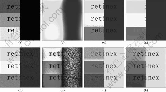
Fig. 2 A synthetic test image: (a) Gray input image; (b) Visualized image; (c), (e), (g) Illumination estimations of MSRCR [6], Elad��s [10], and proposed algorithm; (d), (f), (h) Corresponding Retinex results
A real color image is shown in Fig. 3. Because of the ��gray world�� assumption, the results of MSRCR [6] and Elad��s algorithms [10] over color images with gray-world violations look unnatural. The ��halo�� effect is raised in MSRCR results without edge preserving. Although edge-preserving filtering is taken, the problem still exists in the result of Elad��s algorithm [10], such as the shadow edge of the road in the right-bottom corner in Fig. 3(c). In the proposed algorithm, the interpolation technique is employed instead of spatial filter, and the halo artifact is avoided.
The comparison in details enhancement is shown in Fig. 4. It can be observed that all the results are able to compress the high dynamic range. However, many windows in the second floor are under enhanced in Figs. 4 (b, c, d), and the ground is over enhanced by Funt��s algorithm [5]. The proposed algorithm successfully enhances the visual information that is not visible in the under-exposed regions of the image, since these regions are significantly brightened. Another example is shown in Fig. 5. Compared ith results of other algorithms (Figs. 5(b-d)), the result of the proposed algorithm (Fig. 5(d)) can reveal more details.
Figures 6-8 depict the results of the algorithms for noisy images. Without noise suppression, MSRCR [6] and Funt��s algorithm [5] amplify the noise in under- exposed regions when they enhance details. The second bilateral filter in Elad��s algorithms [10] suppresses noise. However, the correctly exposed regions are blurred, since the whole image is processed by the filter. The proposed algorithm exhibits good contrast, suppresses noise, and successfully preserves the correctly exposed regions. It results from adaptive noise suppression.
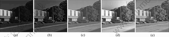
Fig. 3 Test image I: (a) Input image; (b) Result of MSRCR [6]; (c) Result of Elad��s algorithm [10]; (d) Result of Funt��s algorithm [5]; (e) Result of proposed algorithm

Fig. 4 Test image II: (a) Input image; (b) Result of MSRCR [6]; (c) Result of Elad��s algorithm [10]; (d) Result of Funt��s algorithm [5]; (e) Result of proposed algorithm

Fig. 5 Test image III: (a) Input image; (b) Result of MSRCR [6]; (c) Result of Elad��s algorithm [10]; (d) Result of Funt��s algorithm [5]; (e) Result of proposed algorithm
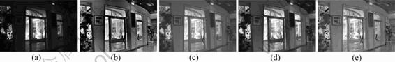
Fig. 6 Test image IV: (a) Input image; (b) Result of MSRCR [6]; (c) Result of Elad��s algorithm [10]; (d) Result of Funt��s algorithm [5]; (e) Result of proposed algorithm
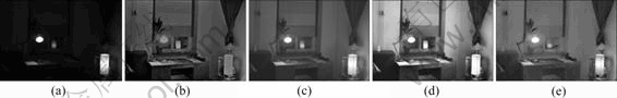
Fig. 7 Test image V: (a) Input image; (b) Result of MSRCR [6]; (c) Result of Elad��s algorithm [10]; (d) Result of Funt��s algorithm [5]; (e) Result of proposed algorithm

Fig. 8 Test image VI: (a) Input image; (b) Result of MSRCR [6]; (c) Result of Elad��s algorithm [10]; (d) Result of Funt��s algorithm [5]; (e) Result of proposed algorithm
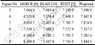
In order to evaluate the different Retinex techniques, image entropy is used in this work, which is a statistical measure of randomness that can be used to characterize the texture of the image, as given in Table 1. The texture contains details and noise. In Figs. 3-5, images are of high quality, and the texture is mainly represented by details. The entropies of the proposed algorithm are greater than others in Figs. 3-5, which proves that more details are revealed in the algorithm. In Figs. 6-8, noise in dark environments is smoothed by noise suppression in the proposed and ELAD��s algorithms. However, MSRCR and FUNT��s algorithms amplify noise, which increases their entropies. The evidence is that the entropy difference between FUNT��s and the proposed results changes with noise levels. Besides, the proposed algorithm has greater entropies than ELAD��s algorithm, both with noise suppression. This is because the correctly exposed regions are blurred when noise suppression is not adaptive in ELAD��s algorithm.
Table 1 Image entropies of test images
6 Conclusions
1) A novel Retinex algorithm is presented, which is achieved mainly by two steps. In the first step, the illumination image is estimated by an interpolation technique after locating the MILPs (pixels containing the illumination information). In the second step, the reflectance image is recovered with adaptive noise suppression, which is posed as an optimization problem.
2) Experimental results demonstrate that the algorithm can efficiently enhance details in the under-exposed regions, avoid the ��halo�� effect, and afford adaptive noise suppression.
3) Speeding up the algorithm is the future work.
References
[1] LAND E, MCCANN J. Lightness and Retinex theory [J]. J Opt Soc Amer, 1971, 61(1): 1-11.
[2] PROVENZI E, Fierro M, Rizzi A, Carli L D, Gadia D, Marini D. Random spray Retinex: A new Retinex implementation to investigate the local properties of the model [J]. IEEE Trans Image Process, 2007, 16(1): 162-171.
[3] Morel J M, Petro A, Sbert C. A PDE formalization of Retinex theory [J]. IEEE Trans Image Process, 2010, 19(11): 2825-2837.
[4] Frankle J, McCann J. Method and apparatus for lightness imaging: US, 4384336 [P]. 1983-05-17.
[5] Funt B, Ciurea F, McCann J. Retinex in Matlab [J]. Journal of the Electronic Imaging, 2004, 13(1): 48-57.
[6] Jobson D J,Rahman Z,Woodell G A. A multiscale Retinex for bridging the gap between color images and the human observation of scenes [J]. IEEE Trans on Image Processing, 1997, 6(7): 965-976.
[7] BertalmIo M, Caselles V, Provenzi E. Issues about Retinex theory and contrast enhancement [J]. Int J Comput Vis, 2009, 83(1): 101-119.
[8] Bertalmio M, Cowan J. Implementing the Retinex algorithm with Wilson-Cowan equations [J]. J Physiol, 2009, 103(1): 69-72.
[9] Kimmel R, Elad M, Shaked A, Keshet R, Sobel I. A variational framework for Retinex [J]. International Journal of Computer Vision, 2003, 52(1): 7-23.
[10] ElaD M. Retinex by two bilateral filters [C]// 5th International Conference on Scale-Space and PDE Methods in Computer Vision.Hofgeismar: Springer, 2005: 217-229.
[11] Xiong Wei-hua, Funt B. Stereo Retinex [J]. Image Vis Comput, 2009, 27(1): 178-188.
[12] Subr K, Soler C, Durand F. Edge-preserving multiscale image decomposition based on local extrema [J]. ACM Trans Graph, 2009, 28(5): 1-9.
[13] levin a, lischinski d, weiss y. Colorization using optimization [J]. ACM Trans Graph, 2004, 23(3): 689-694.
[14] Schechner Y Y, Karpel N. Recovery of underwater visibility and structure by polarization analysis [J]. IEEE J Oceanic Eng, 2005, 30(3): 570-587.
[15] Schechner Y Y, Averbuch Y. Regularized image recovery in scattering media [J]. Pattern Analysis and Machine Intelligence, IEEE Transactions on, 2007, 29(9): 1655-1660.
[16] Kaftory R, Schechner Y Y, Zeevi Y Y. Variational distance-dependent image restoration [C]// Proc IEEE Conf Computer Vision and Pattern Recognition. Minneapolis: IEEE, 2007: 1-8.
[17] Farbman Z, Fattal R, Lischinski D, Szeliski R. Edge-preserving decompositions for multi-scale tone and detail manipulation [J]. ACM Trans Graph, 2008, 27(3): 1-10.
[18] Lischinski D, Farbman Z, Uyttendele M, Szeliski R. Interactive local adjustment of tonal values [J]. ACM Trans Graph, 2006, 25(3): 646-653.
[19] Ghimire D,Lee J. Nonlinear transfer function-based local approach for color image enhancement [J]. Consumer Electronics, IEEE Transactions on, 2011, 57(2): 858-865.
[20] LI Ming. A fast algorithm for color image enhancement with total variation regularization [J]. Science China-Information Science, 2010, 53(9): 1913-1916.
[21] Ferradans S, Bertalmio M, Provenzi E,Caselles V. An analysis of visual adaptation and contrast perception for tone mapping [J]. Pattern Analysis and Machine Intelligence, IEEE Transactions on, 2011, 33(10): 2002-2012.
(Edited by YANG Bing)
Foundation item: Project(61071162) supported by the National Natural Science Foundation of China
Received date: 2011-07-28; Accepted date: 2011-12-12
Corresponding author: LI Wu-jing, PhD Candidate; Tel: +86-13679043723; E-mail: liwujing12345@gmail.com
Abstract: In order to improve image quality, a novel Retinex algorithm for image enhancement was presented. Different from conventional algorithms, it was based on certain defined points containing the illumination information in the intensity image to estimate the illumination. After locating the points, the whole illumination image was computed by an interpolation technique. When attempting to recover the reflectance image, an adaptive method which can be considered as an optimization problem was employed to suppress noise in dark environments and keep details in other areas. For color images, it was taken in the band of each channel separately. Experimental results demonstrate that the proposed algorithm is superior to the traditional Retinex algorithms in image entropy.
