

J. Cent. South Univ. (2018) 25: 392-405
DOI: https://doi.org/10.1007/s11771-018-3745-4

FEM-DEM coupled modeling of cone penetration tests in lunar soil
LIN Cheng-xiang(�ֳ���), TU Fu-bin(Ϳ����), LING Dao-sheng(���ʢ), HU Cheng-bao(���ɱ�)
Institute of Geotechnical Engineering, Zhejiang University, Hangzhou 310058, China
 Central South University Press and Springer-Verlag GmbH Germany, part of Springer Nature 2018
Abstract:
Cone penetration test (CPT) is an appropriate technique for quickly determining the geotechnical properties of lunar soil, which is valuable for in situ lunar exploration. Utilizing a typical coupling method recently developed by the authors, a finite element method (FEM)-discrete element method (DEM) coupled model of CPTs is obtained. A series of CPTs in lunar soil are simulated to qualitatively reveal the flow of particles and the development of resistance throughout the penetration process. In addition, the effects of major factors, such as penetration velocity, penetration depth, cone tip angle, and the low gravity on the Moon surface are investigated.
Key words:
FEM-DEM coupled model; cone penetration test; lunar soil; lunar exploration��
Cite this article as:
LIN Cheng-xiang, TU Fu-bin, LING Dao-sheng, HU Cheng-bao. FEM-DEM coupled modeling of cone penetration tests in lunar soil [J]. Journal of Central South University, 2018, 25(2): 392�C405.
DOI:https://dx.doi.org/https://doi.org/10.1007/s11771-018-3745-41 Introduction
With the ultimate aim of constructing a permanent base on the Moon for human habitation and resource exploitation, a new round of lunar exploration was launched at the beginning of the 21st century. The integration of in situ resource utilization (ISRU) with lunar exploration is a cutting-edge topic that has received increasing attention [1, 2]. The major steps in ISRU include excavation and mining, which are affected by the geotechnical properties of lunar soil, such as bearing capacity and slope stability. Due to the significant environmental differences between the Earth and the Moon, the most importance is that the gravitational field on the Moon is approximately 1/6 of that on the Earth, the initial stress field and the mechanical and geotechnical properties of lunar soil are very different from those of soil on the Earth [3]. In the past two decades, considerable work has been conducted to study Moon-related problems, such as lunar excavation forces [4, 5], lunar soil collapse [6], the specific cutting resistance of lunar regolith simulant [7], the angle of repose for a lunar particle system [8], and the mobility performance of lunar rovers [9�C11]. Further studies are needed to fully understand the geotechnical and mechanical properties of in situ lunar soil for future lunar exploration.
To obtain better insights into the mechanical properties of in situ lunar soil, suitable instruments and techniques that can be performed directly on the lunar surface should be developed [12]. As a major tool for geotechnical characterization in soil mechanics, cone penetration tests (CPTs) were conducted on Earth to study the mechanical properties of lunar soil obtained during the early Apollo Missions [13]. As a sensitive indicator of the packing characteristics of in situ soil, the cone penetration resistance in CPTs can be used as a convenient measurement of lunar soil strength, which is of great importance for excavation and mining during in situ base construction on the Moon surface [14]. The use of CPTs is expected to be extensive during the development of ISRU in future lunar exploration, and the mechanism of CPTs under the low gravity of the lunar surface must be thoroughly investigated [15].
Because laboratory experiments in the field of lunar exploration have many shortcomings, such as high technology demands and very large economic costs, numerical methods have attracted increasing attention in recent years [16]. Unlike in conventional laboratory experiments, the particulate information in a DEM study can be transparent, and the details of microstructure evolution during the loading process can be fully captured and analyzed [17]. Moreover, implementing low gravity conditions is much easier in a DEM simulation. The DEM simulation is widely applied in various aspects of lunar exploration research, e.g., analyzing the wheel performance of a lunar rover [10, 18�C21]. On the other hand, the direct application of DEM remains limited due to the prohibitive computational costs, especially for large-scale or dynamic engineering problems [22]. Therefore, the multi-scale numerical method, which was developed to concurrently simulate different regions using dissimilar models on both the macro and micro scale, appears to be an optimal solution as it inherits the advantages of both the FEM and DEM [23�C26].
The objective of this work is to establish an FEM-DEM coupled model of CPTs in lunar soil using a recently developed coupling method. The qualitative results of numerical modeling can provide a predictive reference for realistic in situ tests on the Moon surface. This paper is organized as follows. First, the theories of FEM and DEM are briefly reviewed. Second, the concept of coupling finite elements and discrete elements is presented. Additionally, an explicit time integration algorithm with multiple time steps is exploited to dramatically reduce computational costs. Next, the properties of lunar soil are summarized for numerical modeling. Using the separate edge coupling method, an FEM-DEM coupled model of CPTs in lunar soil is established. Then, the modeling results and the influence of major factors are qualitatively analyzed in detail, and conclusions are presented.
2 Method for FEM-DEM coupled modeling of CPTs
The most important procedure for creating a coupled model is to formulate an efficient scheme that can transfer key information across the coupled region. In previous literature, there are two main types of coupling schemes: 1) energy-based methods in which a common energy functional with explicit consideration of compatibility is shared by dissimilar models and from which the equilibrium of each model can be derived; and 2) force-based methods in which the compatibility conditions of different models are directly enforced as boundary conditions to obtain the equilibrium of each model. The separate edge coupling method, a state-of-the- art force-based method, is used in this work to create an FEM-DEM coupled model of CPTs in lunar soil.
2.1 Theories of FEM and DEM
For a problem in continuum mechanics, whose region is denoted as �� and whose displacement boundary and surface force boundary are denoted as  1�� and 2��, respectively, the conservation of linear momentum equation can be written as follows:
 in �� (1)
where �� is the mass density;  is the acceleration vector, which is the second derivative of the displacement u with respect to time t;
  is the Hamilton operator; �� and �� are the stress and strain tensors, respectively; D is the fourth-order stiffness tensor; g is the vector of the body force per unit volume.
Assume that the initial conditions are:
 in �� (2)
and the boundary conditions are:
 (3)
(3)
where u0 is the initial displacement vector; v0 is the initial velocity vector;  and
and  are the prescribed displacement on 1�� and the pre-applied traction on 2��, respectively; n is the out-normal of 2��.
The governing equation of the continuum can be obtained in a weak form as follows:

 (4)
(4)
where ��u is the virtual displacement.
Discretizing the continuum region using FEM, the displacement field can be approximated as follows:

 (5)
(5)
where n is the total number of nodes; N is the matrix of the shape function and U is the nodal displacement vector. The following equation can be obtained by substituting Eq. (5) into Eq. (4):
 (6)
(6)
where ��U is the virtual displacement vector of the nodes and M, K and F are the mass matrix, stiffness matrix and force vector, respectively. Denoting the strain matrix as B, then M, K and F can be given as follows:
 (7)
(7)
 (8)
(8)
 (9)
(9)
In DEM, which was first introduced by CUNDALL et al in 1979 [27], the calculation cycle is a time-stepping algorithm that alternatively applies Newton��s second law to each particle and a force-displacement law to each contact. The translational and rotational motions of particle i (1��i��p) can be described by Eqs. (10) and (11), respectively.
 (10)
(10)
 (11)
(11)
where p is the total number of particles; bi is the mass of particle i; ci is the total number of contacts around particle i; xi is the position vector;  is the external force vector; Ii is the inertial moment; ��i is the rotational angle vector;
  is the external moment vector of particle i;
  is the contact force vector between particles i and j; and rij is a vector pointing from the mass center of particle i to the contact between particles i and j.
For a linear contact model, the normal contact force can be computed by:
 (12)
(12)
and the tangential contact force can be computed by:
 (13)
(13)
where  is the relative displacement between particles i and j in the normal direction;
  is the incremental relative displacement between particles i and j in the tangential direction; kn and ks are the normal and tangential contact stiffness, respectively; �� is the contact frictional coefficient.
Rewriting Eqs. (10) and (11) in a weak form, we obtain the following:

 (14)
(14)
in which ��xi and �Ħ�i are the virtual displacements of particle i. Define that:
 (15)
(15)
 (16)
(16)
 (17)
(17)
 (18)
(18)
 (19)
(19)
 (20)
(20)
where E is the unit matrix, and Eq. (14) can then be rewritten in a much simpler form as follows:
 (21)
(21)
2.2 FEM-DEM coupled modeling of CPTs
As shown in Figure 1, the local region of interest in a CPT can be modeled using discrete elements, while the remaining region can be described by a continuum. Denote the regions of the discrete elements as ��m, the regions of the continuum as ��M, and their coupling region as  . Two artificial boundaries are then introduced: ��m for the discrete elements and ��M for the continuum.
To progressively eliminate the freedoms of the continuum in ��m and to generate the artificial boundary ��M, a new model is constructed with an assigned function ��(x) to weight the material properties of the continuum. The mass density �ѡ�, stiffness tensor D�� and body force g�� of the new model satisfy:
 (22)
(22)
The conservation of linear momentum for the new model becomes:
 (23)
(23)
where gC is an undetermined compensation body force that is needed to achieve equilibrium. The force boundary condition of the new model is  on 2��, and the other initial and boundary conditions remain unchanged.

Figure 1 Conventional diagram of an FEM-DEM coupled model of CPTs
The compensation force gC can be obtained from Eq. (1) and Eq. (23) as follows:
 (24)
(24)
Thus, the new model is guaranteed to have the same solution u(x, t) as the original model.
In general, we assume that 0�ܦ�(x)��1. Assign  in
in  and
and  in
in  then
then  in these regions even if
  . In ��C,
  because of the variation of ��(x). In this case, gC or the stress �� has to be determined by the compatibility requirement of the continuum with respect to the discrete elements.
The corresponding weak-form governing equation of the continuum becomes:

 (25)
(25)
Substituting Eq. (5) into Eq. (25), we obtain:
 (26)
(26)
 (27)
(27)
 (28)
(28)
 (29)
(29)
 (30)
(30)
Similarly, another assigned function ��(x) is introduced to weight the material properties of the discrete elements to reduce the number of discrete elements and to generate the artificial boundary ��m. The mass, external force, external moment of particle i and the contact stiffness between particle i and particle j of the new model satisfy:
 (31)
(31)
 (32)
(32)
 (33)
(33)
 (34)
(34)
 (35)
(35)
where  is the position vector of the contact between particle i and particle j. A compensation force
  and a compensation moment
  must be introduced to achieve equilibrium. Then, the translational and rotational motions of particle i are respectively governed by the following equations:

 (36)
(36)

 (37)
(37)
To ensure that the new model has the same solution as the original one, we have:
 (38)
(38)
 (39)
(39)
Implementing the Taylor expansion, Eq. (38) and Eq. (39) become:
 (40)
(40)
 (41)
(41)
For brevity, the governing equations of all particles can be rewritten in matrix form as follows:
 (42)
(42)
in which
 (43)
(43)
 (44)
(44)
 (45)
(45)

 (46)
(46)
 (47)
(47)
In the same way, we assume that 0�ܦ�(x)��1. Assign  in
in  and
and  in
in  then
then  and
and  in these regions. Due to the variation of ��(x) in ��C, and are not zero and will be required to satisfy the compatibility requirement of the discrete elements with respect to the continuum. Note that the weighting functions ��(x) and ��(x) are independent of each other.
��C can be divided into four groups, each with a different coupling scheme, based on the values of ��(x) and ��(x): (1)  : and ; (2)
  : ��(x)<1 and ; (3)
  : and ��(x)<1; and (4)
  : ��(x)<1 and ��(x)<1. As shown in Figure 2, with different choices of the weighting functions ��(x) and ��(x), four typical coupling methods can be derived. Particularly, when
  , a useful coupling method named separate region coupling is obtained, as shown in Figure 2(c). Separate region coupling can be considered a force- based coupling method, with only the displacement compatibility or the force compatibility condition guaranteed. The most important advantage of this method is that the compatibility conditions of dissimilar models can be obtained and imposed on their own. When the widths of both material variation regions approach zero, separate region coupling tends to separate edge coupling, as shown in Figure 2(d); separate edge coupling is used in this work for multi-scale modeling of CPTs in lunar soil.
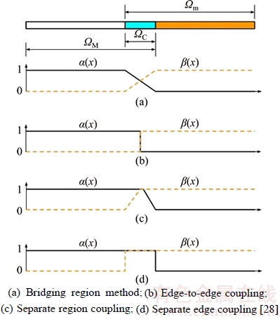
Figure 2 Weighting functions for typical generalized bridging region methods:
The most important assignment of coupling method is to determine gC, and using the compatibility conditions so that the equilibrium of each new model is guaranteed. For separate edge coupling, the material variation regions of the continuum and discrete elements are misaligned, and the corresponding displacement compatibility requirements are individually enforced by the Lagrange multiplier method; its coupling region belongs to group  : and . From Eqs. (21) and (32), we can easily obtain gC=0,
  and
and  Therefore, nothing has to be done with either the continuum or the discrete element model, but a coupling scheme must be formulated to transfer key information between the two models.
2.3 Multiple-time-step algorithm
To reduce computational costs, an explicit integration algorithm with multiple time steps is introduced to integrate the ordinary differential governing equations of FEM and DEM. The displacement, velocity, and acceleration of finite elements and the Lagrange forces are updated at each coarse time step, and the quantities of discrete elements are updated at each fine time step. The coarse time step ��T equals m times the fine time step ��t. For separate edge coupling, the coupling terms will not be introduced until the sum of the fine time steps reaches a coarse time step. Given the quantities of finite elements at macroscale step k and the quantities of discrete elements at microscale substep k, i, the multi-time-step algorithm for separate edge coupling is specified as follows:
1) Compute the displacement of finite elements at each coarse time step and the displacement of discrete elements at each fine time step:
 (48)
(48)
 (49)
(49)
2) Compute the trial acceleration at each microscale substep without coupling terms:
 (50)
(50)
 (51)
(51)
3) Calculate the predictive velocities using the Newmark scheme:
 (52)
(52)
 (53)
(53)
4) Adjust the velocities of different models by introducing the coupling terms:
 (54)
(54)
 (55)
(55)
5) Update the accelerations:
 (56)
(56)
 (57)
(57)
3 FEM-DEM coupled modeling of CPTs in lunar soil
3.1 Material properties of lunar soil
The Moon is covered by a complex layer of unconsolidated debris, known as the lunar regolith or lunar soil [29]. In total, 382 kg of lunar samples have been brought back to Earth since the first successful Moon landing in 1969, and the debris with a diameter of less than 1 cm are defined as ��lunar soil�� in a narrow sense by the Lunar Receiving Laboratory [3]. Our understanding of the characteristics of lunar soil depends mainly on the studies of soil samples returned by the Apollo and Luna missions [30]. The main physical and mechanical properties of lunar soil, used for determining the parameters in FEM-DEM coupled modeling of CPTs in lunar soil, are briefly summarized here.
The main physical and mechanical properties of lunar soil are needed to develop the reliable engineering models, and the determination of these properties is one of the main scientific goals at the initial stage of lunar exploration [31]. The data sources of the Apollo missions indicate that the bulk density and void ratio of lunar soil vary locally and are closely related to soil conditions, as shown in Table 1. In stark contrast with Earth soil, which has a general grain density of about 2.6 to 2.8, the grain density of the returned lunar soil samples is between 2.9 and 3.3, and the recommended value is 3.1 [32].
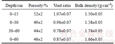
Porosity is a crucial variable that affects the mechanical characteristics of lunar soil, such as compressibility, bearing capacity and shear strength. With increasing depth, the porosity of lunar soil decreases, and the bulk density increases. The best estimates for the average porosity, void ratio and bulk density of in situ lunar soil at different depths in the intercrater areas are shown in Table 2.
Measurements of lunar soil samples conducted by STESKY et al [33] suggested that the Poisson ratio depends strongly on the density of lunar soil. The Poisson ratio of lunar soil samples is about 0.46 at the near-surface area and decreases rapidly with increasing depth. In processing the experimental data obtained by the Surveyor spacecraft, a range of 0�C0.5 was used for the Poisson ratio of lunar soil [34]. As for lunar seismic modeling, a constant Poisson ratio of 0.35 is assumed [35]. Moreover, the mean value of Poisson ratio of lunar soil is estimated to be 0.3 [36]. No direct data are available for the elastic modulus of lunar soil. However, it should be noted that a variety of physical experiments conducted on JSC-1 lunar soil simulant show a elastic modulus interval of 65�C110 MPa for a bulk density of 1.64 g/cm3 [37]. In numerical simulation studies of lunar excavations, values of 100 MPa and 0.3 are used for the elastic modulus and Poisson ratio of the FJS-1 lunar soil simulant, respectively [5].
Table 1 Bulk density and void ratio of lunar soil under different conditions [32]

Table 2 Best estimates of porosity, void ratio, and bulk density of lunar soil at different depths [32]
3.2 Modeling of CPTs in lunar soil
Conventionally, numerical modeling of CPTs can monitor the internal parameters that are difficult to be measured in situ. The additional insights provided by the numerical model can improve the interpretation of the penetrometer-soil interaction. Based on a classical plane strain case, together with the separate edge coupling method discussed above, a series of CPTs in lunar soil are modeled by coupling FEM and DEM to qualitatively reveal the flow of particles and the development of resistance in the penetration process.
As shown in Figure 3, the modeled region has dimensions of 0.62 m in height and 0.66 m in width. The FEM zone is discretized by rectangular mesh elements with a size of  , yielding a total of 76 nodes and 54 elements. Meanwhile, the DEM zone is filled with particles. For simplicity, the inter-particle cohesion and the shape characteristics of real lunar soil particles are neglected. Rounded particles with a radius of 0.003 m are used here to represent lunar soil particles, and their original arrangement is shown in Figure 4. In total, there are 5101 particles in the DEM zone, whose area accounts for approximately one-third of the entire region. The cone penetrometer is assumed to be rigid and to produce no deformation during the penetration process. The penetrometer��s width is 35.7 mm, and its length is 519.6 mm, which is long enough to penetrate through the whole DEM zone. The angle of the cone tip, denoted by ��, varies in different simulated conditions.
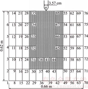
Figure 3 Schematic diagram of FEM-DEM coupled model of CPTs in lunar soil
On the basis of the material properties of lunar soil summarized above, the parameters for the FEM-DEM coupled model of CPTs are determined. The main model parameters are listed in Table 3, as well as the dimensions of the modeled region and cone penetrometer.
In principle, the CPT results can be affected by several factors, such as penetration velocity, penetration depth and cone tip angle. For in situ CPTs in lunar soil, the low gravity is another important factor. Using the FEM-DEM coupled model of CPTs, all these main factors are investigated in the following section. In total, seven conditions are simulated, and their detailed conditions are listed in Table 4.
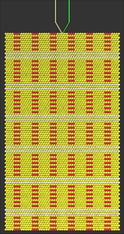
Figure 4 Particles in DEM zone and their original arrangement
3.3 Results and analyses
3.3.1 Effect of penetration velocity
The first three simulated conditions are selected in the model to consider the effects of different penetration velocities. The curves of the specific penetration resistance (Ps), cone tip resistance (Qc) and side frictional resistance (Fs) versus penetration depth for these three penetration velocities are depicted in Figure 5. As shown in the figure, the values of these three resistances generally increase when the penetration velocity increases. Compared to the other two curves, the oscillation of the curve is the smallest when the penetration velocity is 0.3 m/s. In addition, the results of 0.5 m/s are close to those of 0.3 m/s. When the penetration velocity is 0.7 m/s, the cone penetrometer bears the greatest resistances during the penetration process due to the inertia effect of the soil. As a result, the penetration velocity should be limited to a low value when modeling CPTs in a quasi-static process.
3.3.2 Effect of penetration depth
To observe the disturbance on lunar soil particles when the cone penetrometer reaches different depths, we consider the simulated condition (2) as an example. Figure 6 depicts the penetration process as the cone penetrometer going through the particles of the DEM zone to three different depths: s=0.10 m, s=0.25 m, and s=0.40 m.
As shown in Figure 6(a), immediately after the penetration of the cone penetrometer, the lunar soil particles flow sideways and up. The void increases and shear dilatancy appears in the particles around the cone penetrometer. Meanwhile, the particles below the cone tip are slightly disturbed when the penetration depth is rather small. With increasing penetration depth, the effect of the cone penetrometer on the particles becomes stronger. For particles in the lateral direction, the main range of influence is approximately 2 times d (the diameter of the cone penetrometer); and for particles below the cone tip, this range is 4 times d. When s/d>10 (the ratio of penetration depth to the diameter of the cone penetrometer), particles near the cone tip experience a punching shear failure, as shown in Figure 6(c).
A square area with a size of 0.1 m��0.1 m and a center located at (0.432 m, 0.225 m) is selected to examine the change of the void ratio of the particles adjacent to the cone tip during the penetration process. The curve of the void ratio versus penetration depth is drawn in Figure 7. With increasing penetration depth, the disturbance of the particles by the cone penetrometer becomes stronger. The void ratio begins to increase when the penetration depth is approximately 0.1 m and reaches a maximum value when the penetration depth approaches 0.17 m, resulting in shear dilatancy of the particles. Then, the void ratio increases due to the extrusion from the cone penetrometer, leading to shear shrinkage of the particles. Affected by the compressive deformation of the particles, the void ratio finally becomes less than its initial value.
Table 3 Parameters for FEM-DEM coupled model of CPTs in lunar soil

Table 4 Simulated conditions and their corresponding numbers
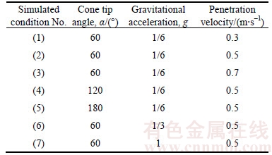
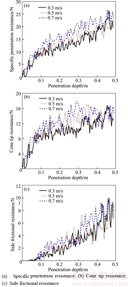
Figure 5 Curves of resistances versus penetration depth at different penetration velocities:
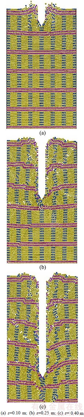
Figure 6 Diagram of penetration process at different penetration depths:
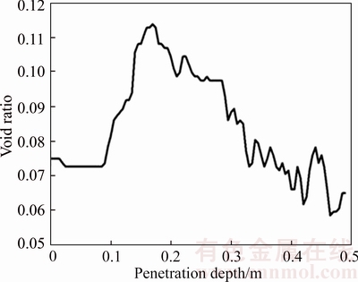
Figure 7 Curve of void ratio of a particular area versus penetration depth
Figure 8 depicts the curves of Ps, Qc and Fs versus penetration depth. As shown in Figure 8, Ps, Qc and Fs gradually increase as the penetration depth increases, and all the curves present zigzag patterns with sharp variations. When the penetration depth s<0.1 m, the side frictional resistance is almost negligible, and the specific penetration resistance is all borne by the cone tip resistance. The side frictional resistance gradually increases with increasing penetration depth when s>0.1 m, and the specific penetration resistance is borne by both the cone tip resistance and the side frictional resistance. The maximum values of Ps, Qc and Fs are 23.0 N, 17.1 N and 9.2 N, respectively. The specific penetration resistance is quite large, while the ratio of side frictional resistance to specific penetration resistance is small, which conforms to the law obtained from CPTs in sandy soil.
3.3.3 Effect of cone tip angle
In an attempt to study the effect of cone tip angle, three simulated conditions with cone tip angles of 60��, 120�� and 180�� are compared and analyzed, and the corresponding distribution contours of the normal contact forces of the particles in the DEM zone are shown in Figures 9�C11, respectively. In all three conditions, the particles below the cone tip have greater normal contact forces than those at other locations. As the cone tip angle increases, the penetration process has less effect on the particles lateral to the cone penetrometer, but the effect on the particles below the cone tip increases. In addition, the normal contact forces of the particles affect a larger range when the cone tip angle increases, which is reflected by greater specific penetration resistance and cone tip resistance. Moreover, smaller penetration depth corresponds with greater cone tip angle when punching shear failure occurs in the particles.

Figure 8 Curves of resistances versus penetration depth in simulated condition (2)
For more detail, the effect of penetration depth can also be shown by the distribution contours of the normal contact forces of particles. When the penetration depth is small, the cone penetrometer acts on particles that are both lateral to the cone penetrometer and below the cone tip. As the penetration depth increases, the area influenced by the cone penetrometer is concentrated in the vertical direction, and the range of particles affected by the penetration action gradually expands. When s/d>10, the particles below the cone tip bear the maximum normal contact forces, undertaking the main penetration action from the cone penetrometer.
3.3.4 Effect of gravity
The environment of the Moon is quite different from that of the Earth; in particular, the gravity on the Moon��s surface is approximately 1/6 of that on the Earth��s surface. The effect of low gravity on CPT mechanism is also analyzed using the FEM-DEM coupled model of CPTs in lunar soil. Gravities of 1g and 1/6g are selected to simulate the environments of the Earth and Moon, respectively. Additionally, 1/3g is simulated to more clearly explain the effect of low gravity. The curves of resistances versus penetration depth under different gravities are shown in Figure 12.
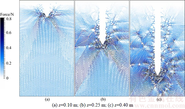
Figure 9 Distribution contour of normal contact forces of particles in DEM zone at different penetration depths when cone tip angle is 60��:
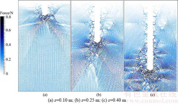
Figure 10 Distribution contour of normal contact forces of particles in DEM zone at different penetration depths when cone tip angle is 120��:
In general, the resistances under low gravity (1/6g or 1/3g) are smaller than the resistance under 1g. Therefore, the cone penetrometer is expected to experience less resistance during the penetration process as the gravity decreases. Thus, the impact of low gravity must be considered when designing equipment and techniques for CPTs conducted on the lunar surface.
4 Conclusions
This paper presents the notion of coupling FEM and DEM and introduces two independent functions to weight the material properties of different models. Based on compatibility conditions, artificial boundaries and compensation forces are derived to ensure the equilibrium of each new model. Using the separate edge coupling method,together with a multi-time-step algorithm, an FEM-DEM coupled model of CPTs was obtained. Compared to the conventional approaches of experiments or simulations, the proposed FEM- DEM coupled model is substantially superior because it can simulate the flow of particles and the development of penetrometer resistances during the penetration progress.
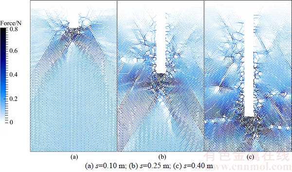
Figure 11 Distribution contours of normal contact forces of particles in DEM zone at different penetration depths when cone tip angle is 180��:

Figure 12 Curves of resistances versus penetration depth under different gravities:
To prepare for future tests conducted on the lunar surface, the results of the proposed FEM- DEM coupled modeling of CPTs offers an alternative way to qualitatively evaluate the geotechnical properties of lunar soil, which is important for in situ excavation and mining during the construction of a base on the Moon. The FEM-DEM coupled modeling results of CPTs in lunar soil show the following:
1) The penetration velocity has clear effect on the penetration mechanism. The specific penetration resistance, cone tip resistance and side frictional resistance generally increase as the penetration velocity increases. To obtain a quasi-static CPT process, the penetration velocity should be limited to a low value in an actual test, as well as in a numerical model.
2) With increasing penetration depth, the specific penetration resistance, cone tip resistance and side frictional resistance of the penetrometer cone increase. The curves of these three resistances versus the penetration depth all present a sharp zigzag pattern. Moreover, the side frictional resistance plays a role only after the penetrometer cone reaches a certain depth.
3) The cone tip angle greatly influences the failure mode and the transfer of the normal contact forces of particles. As the cone tip angle increases, the specific penetration resistance and cone tip resistance increase simultaneously. Whereas, the side frictional resistance is unrelated to the cone tip angle.
4) As the gravity decreases, the specific penetration resistance, the cone tip resistance and the side frictional resistance all decrease. Thus, the effect of low gravity must be particularly taken into consideration when designing equipment and techniques for CPTs conducted on the lunar surface.
Following the progress of science and technology, in situ lunar exploration is entering a flourishing era.FEM-DEM coupled modeling is a promising method for the numerical study of the geotechnical problems of lunar soil, whose results could serve as a predictive reference and reduce the risk of trials for in situ lunar engineering tests. Other coupling methods with different weighting functions ��(x) and ��(x) will be applied and compared in our future work. Additionally, the simulation will be extended to 3D, and the particle shape characteristics will be considered.
References
[1] SANDERS G B, LARSON W E. Intergration of in-situ resource utilization into Lunar/Mars exploration through field analogs [J]. Advances in Space Research, 2011, 47(1): 20�C29.
[2] ANAND M, CRAWFORD I A, BALAT P M, ABANADES S, VANWESTRENEN W, PERAUDEAU G, JAUMANN R, SEBOLDT W. A brief review of chemical and mineralogical resources on the Moon and likely initial in situ resource utilization (ISRU) application [J]. Planetary and Space Science, 2012, 74(1): 42�C48.
[3] OUYANG Zi-yuan. Introduction to lunar science [M]. Beijing: Astronautic Publishing House, 2005: 196. (in Chinese)
[4] BOLES W,SCOTT W, CONNOLLY J. Excavation forces in reduced gravity environment [J]. Aerospace Engineering, 1997, 10(2): 99�C103.
[5] BUI H H, KOBAYASHI T, FUKAGAWA R, WELLS J C. Numerical and experimental studies of gravity effect on the mechanism of lunar excavations [J]. Journal of Terramechanics, 2009, 46(3): 115�C124.
[6] KOBAYASHI T, OCHIAI H, YASUFUKU N, OMINE K. Prediction of soil collapse by lunar surface operations in reduced gravity environment [C]// Proceedings of the 15th International Conference of the ISTVS. Hayama, Japan, 2005: 1�C9.
[7] NAKASHIMA H, SHIOJI Y, TATEYAMA K, AOKI S, KANAMORI H, YOKOYAMA T. Specific cutting resistance of lunar regolith stimulant under low gravity conditions [J]. Journal of Space Engineering, 2008, 1(1): 58�C68.
[8] JI S Y, SHEN H H. Two-dimensional simulation of the angle of repose for a particle system with electrostatic charge under lunar and earth gravity [J]. Journal of Aerospace Engineering, 2009, 22(1): 10�C14.
[9] KOBAYASHI T, FUJIWARA Y, YAMAKAWA J, YASUFUKU N, OMINE K. Mobility performance of a rigid wheel in low gravity environments [J]. Journal of Terra-mechanics, 2010, 47(4): 261�C274.
[10] JIANG M J, LIU F, SHEN Z F, ZHENG M. Distinct element simulation of lugged wheel performance under extraterrestrial environmental effects [J]. Acta Astronautica, 2014a, 99(11): 37�C51.
[11] NAKASHIMA H, KOBAYASHI T. Effects of gravity on rigid rover wheel sinkage and motion resistance assessed using two-dimensional discrete element method [J]. Journal of Terramechanics, 2014, 53(1): 37�C45.
[12] COSTES N C, COHRON G T, MOSS D C. Cone penetration resistance test-an approach to evaluating in-place strength and packing characteristics of lunar soils [C]// Proceedings of the Second Lunar Science Conference. Houston, USA: The M.I.T. Press, 1971: 1973�C1987.
[13] MITCHELL J K, SCOTT R F, HOUSTON W N, COSTES N C, CARRIER W D, BROMWELL L. Mechanical properties of lunar soil: Density, porosity, cohesion, and angle of internal friction [C]// Proceedings of the Third Lunar Science Conference. Houston, USA: ASCE, 1972: 3235�C3253.
[14] HOUSTON W N, NAMIQ L I. Penetration resistance of lunar soils [J]. Journal of Terramechanics, 1971, 8(1): 59�C69.
[15] JIANG Ming-jing, DAI Yong-sheng, WANG Xin-xin. DEM analysis of cone penetration tests under low gravity conditions [J]. Chinese Journal of Geotechnical Engineering, 2014b, 36(11): 2045�C2053. (in Chinese)
[16] LIN Cheng-xiang, LING Dao-sheng, ZHONG Shi-ying. Application of particle flow code numerical simulation in research of geotechnical behavior of lunar soil [J]. Journal of Zhejiang University: Engineering Science, 2015, 49(9): 1679�C1691. (in Chinese)
[17] HUANG Z Y, YANG Z X, WANG Z Y. Discrete element modeling of sand behavior in a biaxial shear test [J]. Journal of Zhejiang University: Science A, 2008, 9(9): 1176�C1183.
[18] NAKASHIMA H, FUJII H, OIDA A, MOMOZU M, KAWASE Y, KANAMORI H, AOKI S, YOKOYAMA T. Parametric analysis of lugged wheel performance for a lunar micro-rover by means of DEM [J]. Journal of Terra- mechanics, 2007, 44(2): 153�C162.
[19] NAKASHIMA H, FUJII H, OIDA A, MOMOZU M, KANAMORI H, AOKI S, YOKOYAMA T, SHIMIZU H, MIYASAKA J, OHDOI K. Discrete element method analysis of single wheel performance for a small lunar rover on sloped terrain [J]. Journal of Terra-mechanics, 2010, 47(5): 307�C321.
[20] LI W, GAO F, JIA Y. Tractive performance analysis on radially deployable wheel configuration of lunar rover vehicle by discrete element method [J]. Chinese Journal of Mechanical Engineering, 2008, 21(5): 13�C18.
[21] LI W, HUANG Y, CUI Y, DONG S J, WANG J. Trafficability analysis of lunar mare terrain by means of the discrete element method for wheeled rover locomotion [J]. Journal of Terra-mechanics, 2010, 47(3): 161�C172.
[22] CUNDALL P A. A discontinuous future for numerical modeling in geomechanics [J]. Geotechnical Engineering, 2001, 149 (1): 41�C47.
[23] ELMEKATI A, SHAMY U E. A practical co-simlation approach for multiscale analysis of geotechnical systems [J]. Computers and Geotechnics, 2010, 37(4): 494�C503.
[24] LI X, WAN K. A bridging scale method for granular materials with discrete particle assembly-Cosserat continuum modeling [J]. Computer and Geotechnics, 2011, 38(8): 1052�C1068.
[25] WELLMANN C, WRIGGERS P. A two-scale model of granular materials [J]. Computer Methods in Applied Mechanics and Engineering, 2012, 205�C208(1): 46�C58.
[26] ROUSSEAU J, FRANGIN E, MARIN P, DAUDEVILLE L. Multidomain finite and discrete elements method for impact analysis of a concrete structure [J]. Engineering Structures, 2009, 31(11): 2735�C2743.
[27] CUNDALL P A, STRACK O D L. A discrete numerical model for granular assemblies [J]. Geot��chnique, 1979, 29(1): 47�C65.
[28] TU F B, LING D S, BU L F,YANG Q D. Generalized bridging region method for coupling finite elements with discrete elements [J]. Computer Methods in Applied Mechanics and Engineering, 2014, 276(7): 509�C533.
[29] CARRIER W D, MITCHELL J K, MAHMOOD A. The nature of lunar soil [J]. Journal of the Soil Mechanic Sand Foundation Division, 1973, 99(10): 813�C832.
[30] MORRIS R V, SCORE R, DARDANO C, HEIKEN G. Handbook of Lunar Soils [C]// Planetary Materials Branch Publication 67. NASA Johnson Space Center, Houston: JSC Publication No. 19069, 1983: 914.
[31] SLYUTA E N. Physical and mechanical properties of the lunar soil (a review) [J]. Solar System Research, 2014, 48(5): 330�C353.
[32] CARRIER W D, OLHOEFT G R, MENDELL W. Physical properties of the lunar surface [C]// HEIKEN G, VANIMAN D, FRENCH B M. Lunar Sourcebook. New York: Cambridge University Press, 1991: 475�C594.
[33] STESKY R M, RENTON B. Compressional and shear wave velocities in powdered rock under low loads [C]// The 8th Proceeding of Lunar Science Conference. Mississauga, Ontario, Canada: Erindale College, 1977: 1225�C1233.
[34] CHOATE R, BATTERSON S A, CHRISTENSEN E M, HUTTON R E, JAFFE L D, JONES R H, KO H Y, SCOTT R F, SPENCER R L, SPERLING F B, SUTTON G H. Lunar surface mechanical properties [J]. Journal of Geophysical Research, 1969, 74(25): 6149�C6174.
[35] TSUJI T, KOBAYASHI T, AOKI S, KANAMORI H, AIZAWA T, MATSUOKA T. Elastic properties of lunar regolith from vertical seismic profiling [C]// Earth and Space 2012: Engineering, Science, Construction, and Operations in Challenging Environments. Pasadena: ASCE, 2012: 84�C93.
[36] CHERKASOV I I, SHVAREV V V. Soviet investigations of the mechanics of lunar soils [J]. Soil Mechanics and Foundation Engineering, 1973, 10(4): 252�C256.
[37] KLOSKY J, STURE S, KO H, BAMES F. Geotechnical behavior of JSC-1 lunar soil simulant [J]. Journal of Aerospace Engineering, 2000, 13(4): 133�C138.
(Edited by YANG Hua)
���ĵ���
������������̽ʵ��FEM-DEM��߶���ϵ�ģ���о�
ժҪ��������ԭλ̽�¹����о���ֱ�Ӷ�����������ѧ���ʼ����о���ֵ��������̽ʵ�飨CPT����һ���ܹ�����ȷ������������ѧ���ʵļ������������ý����з���һ�ֵ���������ۣ��ɹ����һ���������Ԫ��FEM������ɢԪ��DEM���ľ�����̽��߶�ģ�͡����þ�����̽��߶�ģ�ͶԲ�ͬ�����µ�����������̽ʵ�������ģ���о������Խ�ʾ�˾�����̽������������������������������ķ�չ�����ͬʱ��ģ���о��˴�̽�ٶȡ�����Լ���ǶȺ��±�������������������̽��Ӱ�졣
�ؼ��ʣ�FEM-DEM ���ģ�ͣ�������̽ʵ�飻������̽�¹���
Foundation item: Project(51278451) supported by the National Natural Science Foundation of China; Project(LZ12E09001) supported by the Zhejiang Natural Science Foundation, China
Received date: 2016-05-30; Accepted date: 2017-12-20
Corresponding author: LING Dao-sheng, Professor, PhD; Tel: +86�C571�C88208756; E-mail: dsling@zju.edu.cn; ORCID: 0000-0002- 0604-1175
Abstract: Cone penetration test (CPT) is an appropriate technique for quickly determining the geotechnical properties of lunar soil, which is valuable for in situ lunar exploration. Utilizing a typical coupling method recently developed by the authors, a finite element method (FEM)-discrete element method (DEM) coupled model of CPTs is obtained. A series of CPTs in lunar soil are simulated to qualitatively reveal the flow of particles and the development of resistance throughout the penetration process. In addition, the effects of major factors, such as penetration velocity, penetration depth, cone tip angle, and the low gravity on the Moon surface are investigated.
