
J. Cent. South Univ. Technol. (2011) 18: 642-649
DOI: 10.1007/s11771-011-0742-2![]()
Design and implementation of model test installation of heave compensation system of deepsea mining
HU Qiong(����)1, 2, LIU Shao-jun(���پ�) 1, 2, ZHENG Hao(֣�)1, 2
1. School of Mechanical and Electrical Engineering, Central South University, Changsha 410083, China;
2. State Key Laboratory of Deep Sea Mineral Resources Development and Utilization Technology,
Changsha Research Institute of Mining and Metallurgy, Changsha 410012, China
? Central South University Press and Springer-Verlag Berlin Heidelberg 2011
Abstract:
In order to validate the simulation model and develop heave compensation control strategy, heave compensation model tests were performed. The model test installation includes the mining ship motion simulator, the heave compensation system, the lifting pipe simulator, the buffer simulator and the water pool. The tests of mining ship motion simulator show that it is able to perform under the predetermined attitude path smoothly and can meet the requirements of the mining ship motions. The heave compensation effect is more than 60% under random wave and the goal is set to be 50%. The model test results indicate that this heave compensation system is effective and feasible.
Key words:
deepsea mining; heave compensation; model test installation; mining ship; motion simulator; gimbal��
1 Introduction
At present, the pipeline lifting mining system is the most popular deepsea mining system [1-2]. Under the sea wave, the 6 000 m-long lifting pipeline moves with the motion of mining ship, which causes large axial stress on lifting pipeline [3-4]. To ensure the security of mining operation, a heave compensation system is absolutely necessary. Since 1960s, various studies and analyses have been carried out about the heave compensation systems. In 1968, a heave compensation system between travelling block and hook used in oil drilling platform was proposed by VETCD in USA [5]. The hydraulic cylinder displacement was larger than the heave amplitude of wave height and the load of hydraulic cylinders was nearly 600 t. In 1976, a heave compensation device for marine use was proposed by STEVENSON [6]. It included a passive load supporting system and an active force adjusting system. In 1970s, mining ship ��Glomar Explorer�� was built in USA [7]. Minerals of 5 400 m in seabed depth were lifted to the mining ship by the pipeline lifting system and the maximum lifting load was 6 800 t. The outer gimbal ring was capable of accommodating the pitch motion of ship and roll motion was eliminated by the inner gimbal ring. The heave compensation hydraulic cylinders were used to compensate the heave motion. In 1983, an ocean floor dredge system having pneumohydraulic means suitable for providing tripping and heave compensation modes, was proposed by BLANCHET [8]. The system realized two functions: launching and retrieval, and heave compensation. In 1985, a heave compensation system suitable for a drilling pipe suspension system was proposed in the Netherlands [9]. This was a passive system and the stiffness was nonadjustable. In 1998, an active heave compensation device of drilling ship in irregular wave was proposed by KORDE and DRIVE [10]. The active compensation was realized by electro- hydraulic system. In 2003, a heave compensation system of semi-submersible drilling platform was proposed in Norway [11]. The load was carried by buoyancy tank and the pipeline was vertical because of the balance beam.
In fact, the heave compensation system is too large to do the tests in field. In order to speed up the exploitation of the heave compensation system, reduce cost, save manpower and material resources, model tests are used for validating the simulation model and developing the control strategy. Model tests have been carried out about deepsea mining system. A lifting pipe model test installation with 30 m in height and 100 mm in pipe diameter was built by KIGAM (Korean Institute of Geoscience and Mineral Resources) [12]. Study of hydraulic transport of large solids in hoses was carried out by NIOT (National Institute of Ocean Technology) and IIT (Indian Institute of Technology). A flexible hose model test installation was built to determine the pressure loss in the flow of large solids through hoses [13]. A 30 m-high lifting system model test installation was set up by CRIMM (Changsha Research Institute of Mining and Metallurgy) in China. Pump performance and transport properties were tested [14]. Light-load, media-load and heavy-load active heave compensation systems were proposed by XIAO et al [15-16]. It was based on electro-hydraulic proportional control and intelligent control.
Model test system of Guangdong University of Technology, China, was focused on heave compensation without roll and pitch compensation. And mining ship simulator has single degree of freedom (DOF) without water pool. The heave compensation systems mentioned above are mostly used in oil and gas drilling platforms. Based on heave compensation system of ��Glomar Explorer�� which is the only one designed for the pipeline lifting deepsea mining system [17], a heave compensation system with gimbal platform for pitch and roll compensation and electro-hydraulic system for active heave compensation was proposed. And the heave compensation model test installation with 6-DOF mining ship simulator was built.
2 General structure design of model test installation
Two possible schemes can realize the model tests of heave compensation. The first one is the ship model scheme, as shown in Fig.1. This scheme includes a ship model, a heave compensation system, a wave machine and a water pool. The ship model and wave machine are expensive and the water pool is very large because of the wall effect.

Fig.1 Ship model scheme
The second one is shown in Fig.2 and is composed of a mining ship motion simulator, a heave compensation system, a lifting pipe simulator, a buffer simulator and a water pool. The Steward 6-DOF platform is selected as the mining ship motion simulator and the platform provides six freedom weaving movements in parallel and revolving directions of X, Y and Z axes. The active heave compensation system includes a heave-compensated platform to compensate the heave motion and a gimbal platform to accommodate pitch and roll [7]. The lifting pipe simulator is connected with the heave-compensated platform and moves with the pistons of heave- compensated cylinders. The buffer simulator and part of the lifting pipe simulator are in water.
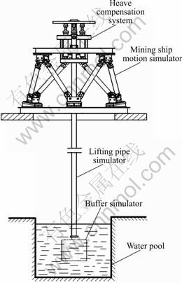
Fig.2 Mining ship motion simulator scheme
Compared with ship model scheme, the mining ship motion simulator shows the strong feasibility and economy. So, it is chosen as the model test installation scheme.
3 Design of model test installation
3.1 Overall view
The model test installation of heave compensation system shown in Fig.3 was built up in the lab. The mining ship motion simulator, heave compensation system and control cabinet are on the second floor and the water pool is on the first floor.
3.2 Mining ship motion simulator
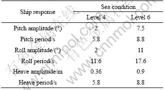
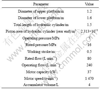
There are six motions of mining ship: pitch, roll, yaw, surge, sway and heave. Yaw, surge and sway can be eliminated by ship dynamic positioning. Therefore, pitch, roll and heave compensation are considered here. Table 1 gives the ship response of level 4 and level 6 sea condition at sea trial site [18]. Based on similar principles, the simulator motion range is determined: the pitch and roll angle is less than 20�� and heave amplitude is less than 200 mm. The parameters of mining ship motion simulator are listed in Table 2.

Fig.3 Photos of model test installation of heave compensation: (a) Mining ship motion simulator and heave compensation system; (b) Lifting pipe simulator, buffer simulator and water pool
Table 1 Ship response at sea trial site
The mining ship motion simulator can be divided into hydraulic system and control system. The hydraulic system is composed of six hydraulic cylinders, six electro-hydraulic proportional valves, three hydraulic accumulators and a hydraulic station. The motions of hydraulic cylinders are controlled by electro-hydraulic proportional valves. The valves are DLHZO-TE-040-L71 with DLHZO-TE-040-L71-SP-ZH-7P electronic amplifiers from Atos. Two hydraulic cylinders share one accumulator. To ensure the constant oil working pressure, a variable displacement pump is chosen. Therefore, the oil pressure is nearly constant to make sure that the same control voltage means reproducibly the same velocity of hydraulic cylinder.
3.3 Compensation system
Research on heave compensation of deepsea mining began at 1970s and the pneumatic hydraulic passive compensation system was popular. In order to improve the efficiency of heave compensation and reduce the energy consumption, active heave compensation was proposed. Here, active heave compensation was selected.
Table 2 Parameters of mining ship motion simulator
The active heave compensation system shown in Fig.4 includes a heave-compensated platform to compensate heave motion and a gimbaled platform to accommodate pitch and roll [19]. The former is supported by four hydraulic cylinders controlled by the same control system as the mining ship motion simulator. The gimbal platform shown in Fig.5 consists of an inner gimbal ring and an outer gimbal ring. The outer gimbal ring is supported on the upper platform of the ship motion simulator. The inner gimbal ring is connected with the heave compensation cylinders. The gimbal system is capable of accommodating the relative motion between the ship and pipe string of roll and pitch. The heave motion is eliminated by active control of the heave compensation cylinders. Here, two of the cylinders are controlled and the other two are used as the guiding rods. The active control is implemented by the same control system of mining ship motion simulator.
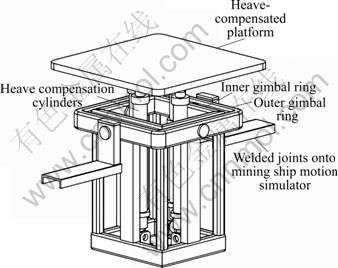
Fig.4 Schematic diagram of heave compensation system

Fig.5 Schematic diagram of gimbal platform
3.4 Lifting pipe simulator and buffer simulator
The lifting pipe simulator is made up of several steel pipes with 2 m in length and 47 mm in outer diameter. The upper end of the pipe is connected with the heave-compensated platform by a universal joint. The bottom end connected with the buffer simulator is immersed in the water pool. The buffer simulator is made up of 12 square steel plates. Each plate weighs 10 kg and measures 264 mm �� 264 mm �� 20 mm, as shown in Fig.3(b).
3.5 Control system
The mining ship motion simulator and the heave compensation system share the same control system. The core of the control system is an opto22 SNAP-PAC-S1 programmable automation controller. SNAP-PAC-S1 is in charge of the intelligent control algorithms, data acquisition, proportional valve control signal output, switch input and output. It provides powerful real-time control and communications to meet industrial control, monitoring, and data acquisition needs. The input and output modules are all Opto products. The displacement of hydraulic cylinders, oil pressure and temperature signals are sampled by analog input modules. Analog output modules give out control voltages to control the flow and direction of electro-hydraulic proportional valves. And the hydraulic station is controlled remotely by opto22 SNAP-PAC-S1. The system can make a real time display of the operating parameters and all the data is saved.
The control system includes the following components:
1) One Ethernet intelligent processor SNAP-PAC- EB1;
2) Two four-channel DC input modules IDC5D (2.5-28 V): start/stop buttons of hydraulic station motor, proportional valve power and automatic load of hydraulic station, two filter blocking alarm;
3) One four-channel AC 220 V switch output module OAC5: indicator lamps of hydraulic station motor, proportional valve power and automatic load of hydraulic station, two sound-light alarms of filters;
4) Four two-channel analog voltage output modules AOV-27: six electronic amplifiers of proportional valves of mining ship motion simulator and one electronic amplifier of proportional valve of heave compensation system;
5) Three four-channel analog current input modules AIMA-4: six displacement sensors of hydraulic cylinders of mining ship motion simulator and three displacement sensors of heave compensation system;
6) Two eight-channel analog current input modules AIMA-8: oil pressure of the cylinders;
7) One two-channel temperature input module AIRTD: temperature of hydraulic station oil and the lab.
4 Experiments of mining ship motion simulator
In order to make sure that the mining ship motion simulator can follow the predetermined attitude, PID control was selected to control the hydraulic cylinders of the simulator. Figure 6 shows the closed loop flow diagram of mining ship motion simulator. ��, ��, ��, x, y and z are platform attitudes. L1, L2, L3, L4, L5 and L6 are displacements of hydraulic cylinders. v1, v2, v3, v4, v5 and v6 are the calculated velocities of hydraulic cylinders. The aim is to control the displacement of the six hydraulic cylinders according to the direct and inverse kinematics solutions. First, the displacements L1-L6 of every cylinder at every step were calculated according to the predetermined platform attitude. Second, the velocities v1-v6 of every cylinder were obtained. The six cylinders moved at the uniform speed in every step. Then, the actual displacements ![]() were measured and the actual velocities
were measured and the actual velocities ![]() were calculated. At last, the control voltages were given according to the velocity PID control. The PID parameters were determined during the tests.
were calculated. At last, the control voltages were given according to the velocity PID control. The PID parameters were determined during the tests.

Fig.6 Closed loop flow diagram of mining ship motion simulator
In order to realize closed loop control of the platform, direct and inverse solution must be conducted. Direct solution is to solve platform attitude according to the six lengths of hydraulic cylinders, and inverse solution is just the contrary calculation.
As shown in Fig.7, six upper hinge joints Ai (i=1, 2, 3, 4, 5, 6) are located at the radius of ra. The six underside hinge joints Bi (i=1, 2, 3, 4, 5, 6) are located at the radius of rb. The circle center of upper circumference is selected as coordinate origin. The coordinate OXYZ is fixed on the upper platform and static coordinate O��X��Y��Z�� is on the underside platform. The initial height (the vertical height between upper and underside hinge joints) of moving platform is h.
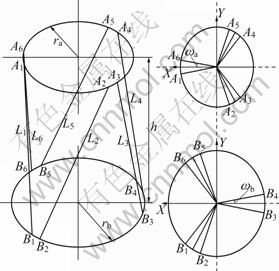
Fig.7 Structural diagram of six-DOF platform
From the geometric relation of Fig.7, the coordinates of upper and underside hinge joints are given:
 (1)
(1)
where ![]()
![]() A3=rasin(30-��a), A4=racos(30-��a),
A3=rasin(30-��a), A4=racos(30-��a), ![]() A6=rasin(60-��a).
A6=rasin(60-��a).
 (2)
(2)
where ![]()
![]() B3=rbsin(30-��b), B4=rbcos(30-��b),
B3=rbsin(30-��b), B4=rbcos(30-��b),![]() B6=rbsin(60-��b).
B6=rbsin(60-��b).
When the attitude of the moving platform is Q=(��, ��, ��, xp, yp, zp), the transformation matrix is given by
 (3)
(3)
where �� is the roll amplitude, �� is the pitch amplitude, �� is the yaw amplitude, xp is the displacement along O��X��, yp is the displacement along O��Y��, and zp is the displacement along O��Z��. ��c�� means ��cos��, and ��s�� means ��sin��. For example, ��s��c�¡� means ��sin��cos�¡�.
Thus, the coordinate of upper hinge joints in static coordinate are given by
P=R?A (4)
Then, the inverse solution is obtained and the lengths of hydraulic cylinders can be given by
![]() (5)
(5)
To realize the direct solution, nonlinear equations are built:
![]() (6)
(6)
The nonlinear equations are solved by iterative algorithm in the Matlab.
In the test, the predetermined motions were harmonic and sea condition was level 6. According to Table 1 and the similarity principles, the pitch and roll amplitude were set to be 15�� and heave amplitude was 90 mm. The pitch and heave period were set to be 8.8 s and roll period was 17.6 s. The displacement of every hydraulic cylinder was saved and the actual platform attitude could be solved through direct solution. The results are shown in Figs.8-10. The platform is able to perform the following predetermined attitude path. The results also show control errors. There are three main reasons: first, to simplify the math model of 6-DOF platform, the cross hinge was simplified as one point; Second, the mechanical error including machining error and installation error was inevitable; Third, velocity PID control was implemented, but attitude closed loop control was not realized.
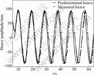
Fig.8 Heave motion of mining ship motion simulator

Fig.9 Pitch motion of mining ship motion simulator

Fig.10 Roll motion of mining ship motion simulator
5 Model tests of heave compensation
The test results indicate that the pitch and roll compensation of the test installation could be completed by the gimbal platform without control. The heave compensation control is realized by PID. Figure 11 shows the closed loop flow diagram of heave compensation. The displacement of the heave- compensated platform S1 and the displacement of the ship motion simulator S2 are obtained by displacement sensors. The aim of heave compensation is that the heave-compensated platform moves the same displacement as the mining ship motion simulator but the directions are opposite. That is to say, the sum of S1 and S2 is constant. Two heave compensation hydraulic cylinders are controlled by one electro-hydraulic proportional valve. The displacements of the two cylinders are measured. The two displacements are almost the same, which indicates that the cylinder synchronization is good.

Fig.11 Closed loop flow diagram of heave compensation
Figures 12 and 13 show the test results of harmonic motion of ship motion simulator under level 6 and level 4 sea condition, respectively. The mining ship motion parameters were determined according to Table 1 and the similarity principles. The heave amplitude of harmonic motion was 90 mm and the period was 8.8 s under level 6 sea condition. The heave amplitude of harmonic motion was 36 mm and the period was 5.8 s under level 4 sea condition. The compensation effect under level 6 sea condition is 80% compared with 72% under level 4 sea condition. The results indicate that the heave compensation effect decreases with increasing the frequency of mining ship motion. Figure 14 shows the test results of random motion of ship motion simulator. The significant wave height of random wave was 4.9 m. The response of mining ship was calculated and the motion of mining ship simulator was determined according to the similarity principles. The compensation effect under random wave is about 60% and is worse than that under harmonic wave. The main reason is that the existence of high-frequency components of the random wave. In general, the active heave compensation is successful and it is feasible.
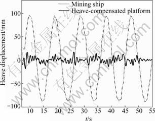
Fig.12 Heave compensation of harmonic motion under level 6 sea condition

Fig.13 Heave compensation of harmonic motion under level 4 sea condition

Fig.14 Heave compensation of random motion
6 Conclusions
1) The motion error of mining ship motion simulator exists. The actual motion of mining ship is random. That is to say, if the mining ship motion simulator can follow the predetermined amplitude and period, the requirements of the mining ship motion simulator are reached. The simulator can also be used as 6-DOF platform in other areas.
2) The heave compensation is successful with the pitch and roll motion of mining ship motion simulator. Heave compensation effect decreases with increasing the frequency of mining ship motion. Because of the high-frequency components of random wave, the heave compensation effect is 60% and is worse than that of harmonic wave.
3) The requirement of heave compensation effect is more than 50% under random wave. It is more than 60% in the test. This heave compensation system is effective and feasible and can be an option of practical project.
References
[1] LIU Shao-jun, WANG Gang, LI Li. Virtual reality research of ocean poly-metallic nodule mining based on COMRA mining system [C]// Proceedings of 5th ISOPE Ocean Mining Symposium. Tsukuba: International Society of Offshore and Polar Engineers, 2003: 104-111.
[2] CHUNG J S. Deep-ocean mining technology: Development II [C]// Proceedings of 6th ISOPE Ocean Mining Symposium (OMS-2005). Changsha: International Society of Offshore and Polar Engineers, 2005: 1-6.
[3] CHUNG J S. The Hughes Glomar Explorer and a 5,000-m-long heavy-hift pipe: Coupled ship and pipe motions measured in North Pacific ocean [C]// Proceedings of 19th International Society of Offshore and Polar Engineers Conference. Osaka: International Society of Offshore and Polar Engineers, 2009: 330-335.
[4] FENG Ya-li, LI Hao-ran, ZHANG Yun-xian. Axial oscillation of a 5 000 m lifting pipe [J]. Metal Mine, 1999, 51(4): 11-18. (in Chinese)
[5] FANG Hua-can. Theoretical basis of offshore oil drilling equipment [M]. Beijing: Petroleum Industry Press, 1984: 285. (in Chinese)
[6] STEVESON W D. Heave compensation device for marine use: US 3946559 [P]. 1976-03-30.
[7] McNARY J F, PERSON A, OZUDOGRU Y H. A 7 500-ton-capacity, shipboard, completely gimbaled and heave-compensated platform [J]. Journal of Petroleum Technology, 1977, 29(4): 439-448.
[8] BLANCHET J. Ocean floor dredge system having a pneumohydraulic means suitable for providing tripping and heave compensation modes: US 4382361 [P]. 1983-05-10.
[9] LANG D, ERIC P. Heave compensation for a pipeline hoisting system: US, WO 85/01775 [P]. 1985-04-25.
[10] KORDE U A, DRIVE A. Active heave compensation on drill-ships in irregular waves [J]. Ocean Engineering, 1998, 25(7): 541-561.
[11] KNUTESN H, ANDRESEN J. Heave compensation system: US, WO071862 A1 [P]. 2004-02-17.
[12] YOON C H, PARK Y C, PARK J M, KIM Y J, KANG J S, KWON S K. Solid-liquid flow experiment with real and artificial manganese nodules in flexible hoses [J]. International Journal of Offshore and Polar Engineering, 2009, 19(1): 77-79.
[13] DEEPAK C R, RAMJI S, RAMESH N R. Development and testing of underwater mining systems for long term operations using flexible riser [C]// Proceedings of 8th ISOPE Ocean Mining Symposium (OMS-2007). Prague: International Society of Offshore and Polar Engineers, 2007: 166-170
[14] YANG Ning, TANG Da-sheng, YANG Ling. The lifting installation of manganese nodules and pump test [C]// Proceedings of 8th ISOPE Pacific/Asia Offshore Mechanics Symposium. Bangkok: International Society of Offshore and Polar Engineers, 2008: 30-35.
[15] XIAO Ti-bing, WU Bai-hai. Design and experimental study of heave compensation simulating test system [J]. Machine Tool & Hydraulics, 2003(4): 36-39. (in Chinese)
[16] XIAO Ti-bing, WU Bai-hai, LUO Zhong-hui. Research on design and simulation of active heave compensation system of heavy lifting mine pipeline [J]. Machine Tool & Hydraulics, 2002(6): 47-51. (in Chinese)
[17] CHUNG J S. Motion and positioning control of deep-ocean ship�Criser�Cequipment system: Deep-ocean test experiences for doing deeper [C]// Proceedings of 3rd International Deep-Ocean Technology Symposium. Beijing: International Society of Offshore and Polar Engineers, 2009: 90-97.
[18] HU Qiong, LIU Shao-jun. Research on physical simulation test installation of heave compensation system of deepsea mining [C]// Proceedings of 8th ISOPE Ocean Mining Symposium (OMS-2009). Chennai: International Society of Offshore and Polar Engineers, 2009: 204-207.
[19] HU Qiong, ZHENG Hao, LIU Shao-jun, YANG Ning. A hardware-in-the-loop simulation system of heave compensation of deepsea mining [C]// Proceedings of 8th ISOPE Ocean Mining Symposium (OMS-2009). Chennai: International Society of Offshore and Polar Engineers, 2009: 197-203.
(Edited by YANG Bing)
Foundation item: Project(50675226) supported by the National Natural Science Foundation of China; Project(DYXM-115-04-02-01) supported by the Eleventh Five-Year Plan of China
Received date: 2010-09-29; Accepted date: 2010-12-30
Corresponding author: LIU Shao-jun, Professor, PhD; Tel: +86-731-88877853; E-mail: liushaojun@mail.csu.edu.cn
