
DOI: 10.11817/j.issn.1672-7207.2015.07.004
ϸ�۳߶��Ͽ��ǻ�ѧ��ӦӰ��Ļ�����̼���ٶ�
������1��Ǯ����2��������1��������1
(1. ������ѧ ���������뻷��ѧԺ������ ������315211��
2. ���ϴ�ѧ ���Ͽ�ѧ�빤��ѧԺ, ���� �Ͼ���211189)
ժ Ҫ��
���ڻ��������Ĵ�����ƺ���Ч�������ۣ�������ǵ�Ч��϶�ʺ�̼����Ӧ��������(1+K��CO2)Ӱ��ķ����Զ�����̼����ģ�ͣ���������ֵĸ�ʽ����������ж�����̼Ũ�ȷֲ���ʱ�շֲ���������������Ļ�������϶��ҺpH�ļ��㹫ʽ��ȷ���������ڲ�̼ͬ�����ڵ�̼���̶ȡ�ͨ���Ի���������̼������������ֵ�������ĶԱȷ������о��������������̼����ȼ���������������ʱ��ı仯���ƻ�����ͬ��������̼ͬ������ʱ���ߵ���ֵ�����Ϊ0.95 mm����֪��������ϸ�۳߶��Ͽ���̼����ӦӰ��Ļ�����̼��ģ�Ϳ��ԺܺöԵ�ˮ���Ȼ�������̼������������з�����Ԥ�⡣
�ؼ��ʣ�
ϸ�۳߶���̼����Ӧ������Һ�����������̼��ģ����
��ͼ����ţ�TU53 ���ױ�־�룺A ���±�ţ�1672-7207(2015)07-2412-07
Concrete carbonation progress on meso-microscopic scale considering effects of chemical reaction
BA Mingfang1, QIAN Chunxiang2, LIU Junzhe1, HE Zhimin1
(1. Faculty of Architectural Civil Engineering and Environment, Ningbo University, Ningbo 315211, China;
2. School of Materials Science and Engineering, Southeast University, Nanjing 211189, China)
Abstract: Based on the CO2 transmission mechanism in concrete and the effective media theory, CO2 transport model considering the effects of equivalent porosity and carbonation reaction retarding factor was provided. Then the finite difference scheme was adopted to calculate the time-space concentration distribution of CO2 in concrete. Furthermore, combining the established pH calculating forum of concrete pore solution, the concrete carbonation degree at different ages was determined. Finally by comparing the calculating carbonation depth with the experimental ones, it is found that the results of accelerated carbonation depth has nearly the same changing trend as those of the experimental results, and the maximum difference of above both is only 0.95 mm at the same time. And thus the proposed carbonation model can be used to analyze and predict the carbonation characteristics of concrete with low binder to water ratio.
Key words: meso-microscopic scale; carbonation reaction; porous solution basicity; concrete carbonation model
������̼��������һ��ӵ�������ѧ����[1-4]������������Ҫ�������µ���ɢ�ͷ�Ӧ���̣�һ����CO2��������̬���ŷDZ��ͻ������ڲ������϶�������ڲ���ɢ���ܽ��ڿ�϶��Һ��CO2��һ������Һ̬��ʽ���ŷDZ��ͻ������ڲ���Һ��ͨ�����ڲ���ɢ�ƽ���һ���ַ�����������һ��Ũ�ȵ�H+��CO32-������������Һ�е�OH-�����кͷ�Ӧ��������̼����������2�����̴����������ƽ���һ������£�CO2�����������е���ɢ�ٶ�ҪԶ��������Һ���е���ɢ�ٶȣ���ˣ�ͨ����CO2�ڿ�϶��Һ����ɢ���ԣ�ʵ�������̼���;���Ԥ����ԣ������ĺ��Իᵼ��һ������һ���棬��Ȼ������̼��������һ������ɢ���ƵĻ�ѧ��Ӧ���̣�����ʵ�ʵ�̼����Ӧ���ٶȲ�һ���㹻�죬��ˣ��dz��б�Ҫ����̼����Ӧ�ٶȶԻ�����CO2��ɢ�ٶȵ�Ӱ�졣��ǰ�����������̼��ģ�;�������̬����ɢϵ������ķ���̬��ɢΪ����[5-8]��ʵ���ϻ������۽ṹ��������Ӧ��̼����Ӧ�ٶȣ����ᵼ�»�����CO2��ɢϵ����ʱ�䷢��һ���ı仯[9-12]����ˣ�����������Ҫ���Ե�ǰ���е�̼��Ԥ��ģ��Ϊ��������Ӷ�����̼��Ч��ɢϵ���Ͷ�����̼��Ӧ��������2���������֣�����ϸ�۳߶��Ͽ���̼����Ӧ�ٶ�Ӱ��Ļ�����̼��ģ�ͣ�����ģ�ͽ�����ֵ�������֤��
1 CO2Ũ��ʱ�ձ仯���̵����
1.1 �����ٶ�
1) ������������������CO2Ũ��Ϊ[CO2]0������̼����ȵ��ƽ�CO2Ũ�ȳ��ַ����Խ��͡�
2) ���������ϱ�������30%ʱ�����ѻ����������ɽ���ͼ�����ɵĶ�Ԫ�ṹ�����н������л�����������ɡ����ʵ����CO2�������϶���ṹ�����еĴ��䣬���Ҵ��������ѭFick�ڶ����ɡ�
3) CO2�ܽ��ڿ�϶��Һ�������ɵ�CO32-������Һ�и����ӷ���һ������̼����Ӧ������̼����Ӧ�ٶ�Ҫ����CO2����ɢ�ٶȣ���̼����Ӧ��ƽ�ⳣ��KCO2��
1.2 ������̼Ũ��ʱ�շֲ�ģ��
������Ϊ�DZ��Ͷ���ʣ���������Ч��϶�ʦ�eq[13]�������������غ㶨�ɺ�Fick�ڶ����ɣ�ȷ����������CO2Ũ����̼������tc�;���̼����ʼ���λ��x�ı仯��ϵΪ

 (1)
(1)
ʽ�У� Ϊ�ܽ�ƽ��ʱҺ��CO2��Ũ�ȣ�mol/m3��
 Ϊ�ܽ�ƽ��ʱ����CO2��Ũ�ȣ�mol/m3��
 Ϊ��Ч��϶�ʣ�m3/m3��
 ΪҺ��CO2����Ч��ɢϵ����m2/h��
 Ϊ����CO2����Ч��ɢϵ����m2/h��
 Ϊ̼����Ӧ����CO2�ı仯�ʣ�mol/(L3��d)��tcΪ̼�����ڣ�d��xΪ����CO2��ɢ��ʼ��ľ��룬m��SΪ��϶ˮ���Ͷȣ�S=w/��cap��
���ڷ��ۻ�����������ˮ�ķDZ���״̬����˻����������϶��Һ����������״̬�����ǵ�CO2�ڿ�϶�����Һ�����ɢ�ٶ����ϴ���ˣ������������ڷDZ�����������ɢ���й��о��ɹ�[14-15]��ȷ��CO2�ڷDZ��ͻ���������ĵ�Ч��϶�ʶ���Ϊ
 (2)
(2)
ʽ�У� Ϊ������ëϸ��϶�ʣ�m3/m3��wΪ���������ʪ������m3/m3��HΪ�����ٺ���������AΪ������������ռ������%��
CO2�����ڷDZ��Ϳ�϶�д����ܽ�ƽ���[16]������ﵽ�ܽ�ƽ��ʱҺ��Ũ��������Ũ�ȵı�ֵ��Ϊ�����ٺ�������H���� ����ˣ�ʽ(1)����ת��Ϊ���µ���ʽ��
 (3)
(3)
ʽ�У� =
= ��Ϊ������̼�ڻ������е���Ч��ɢϵ������ʽ��
1.3 ��������϶��Һ���
�ܽ��ڻ�������϶��Һ�е�CO2�����˷����������ܽ�(��������)�⣬������ϵ�е�����̣������Կ�϶��Һ��Na+��K+��CaCO3�������ɵ�Ca2+��Ӱ�죬���϶��Һ�и��ɷֵ�ƽ�ⳣ�����ܶȻ��������£�
 (4)
(4)
 (5)
(5)
 (6)
(6)
 (7)
(7)
CSH [H��Si��O��Ca��]++[OH]- (8)
ʽ�У� ΪCO2����ĺ���������22 ��ʱΪ3.66��10-4 mol/(m3��Pa)��
 Ϊ��϶��CO2�����ѹ��Pa��[ ]��ʾ��϶��Һ��ij�ֳɷֵ�Ũ�ȣ�mol/L3��
 Ϊ��������(CH)�ܶȻ�������CSHΪˮ���������д��
 ��
�� �ֱ�ΪCO2��H2Oһ���Ͷ��������ƽ�ⳣ�������¶��йأ�������������о��鹫ʽ����һ���¶������ĵ���ƽ�ⳣ����
 (9)
(9)
ʽ�У�TΪ����ѧ�¶ȣ�K��
�ָ���ʽ(4)~(6)��ʾ�ĵ���ƽ��ʽ�����Եõ���������϶��Һ��CO2������̬��ƽ��Ũ�ȷֱ�Ϊ��


 (10)
(10)
��ˣ�������Һ�ĵ����Ի�ԭ���ɵ�
 (11)
(11)
ʽ�У�[C]TΪ��϶��Һ�и�����ʽC��Ũ�ȣ�mol/L�� ��
�� �ֱ�Ϊ
�ֱ�Ϊ ��
�� ռ��Һ�и�����̬CO2������Ħ��������KWΪˮ�ĵ��볣�������¶��йأ�
 ��SCHΪ��϶��Һ���������Ƶı���Ũ��mol/L�����¶��йأ�SCSHΪ��϶��Һ��ˮ�������(CSH)�ı���Ũ�ȣ�mol/L�����¶��йء�
����CO2��ˮ�д���CO2��H2O����ʽ�����⣬�м��ٲ��ַ������룬��ˣ���϶��Һ���ܽ��CO2��Ũ�ȿ��Խ��Ƶ��ڲ��ú������ɼ��������
 (12)
(12)
ʵ���ϻ������ڲ��������ƺ�ˮ������Ƶ�̼����Ӧ������ͬ�����еģ����Ǵ���һ���IJ����[17-19]��CSH�ڿ�϶��Һ���ܽ�ȼ��ͣ���϶��ҺpHΪ11ʱCSH�Կ�϶��Һ��ȵĹ���ʮ�����ޣ����Բ��迼�ǡ�����ֽ����ۻ�Ĥʧ��ʱ�Ŀ�϶��Һ���(pH=11)��Ϊ�ж���Ƭ����������̼�������ݡ���ˣ����Եõ�һ���¶��»�������϶��Һ�й���������Ũ��[H+]��һԪ���η��̣�

 (13)
(13)
��ʽ(13)���Եõ�pH =11����Ӧ��һ���¶�������CO2Һ���Ũ�ȣ���˿��Ը���CO2��Ũ�ȷֲ�ȷ����Ӧ��̼����ȡ�
1.4 ������̼�������ʵ�ȷ��
����1.1�ڼٶ�������������̼��������CO2����������Ϊ
 (14)
(14)
ʽ�У� Ϊ̼����Ӧ�ٶȳ�����L/(mol��s)��[Ca2+]Ϊһ���¶���������Һ�и����ӵ�Ũ�ȣ�mol/L��
��ʽ(7)��(10)����ʽ(14)�е�
 (15)
(15)
ʽ�У�KQΪCO2��������ϵ����mol/(L��s)��
ʽ(15)��̼����Ӧ���ٶȳ���kCO2�뷴Ӧ���������Ũ���أ���ֻ�뷴Ӧ�¶��йأ���(20��2) ��ʱ����Ϊ2.041 L/(mol��s )[15]��
2 ̼��ģ�Ͳ�����ȷ��
2.1 CO2��Ч��ɢϵ����ȷ��
���ݼٶ�������̼����Ӧ�����ɵ�CaCO3��Ũ����Ҫȡ����̼������ӵ�Ũ�ȣ���
 (16)
(16)
ʽ�У�KCO2ΪҺ��̼�������CO32-�������Ca2+����̼����Ӧ��ƽ�ⳣ����[CaCO3]ΪCO2̼����Ӧ���ɵ�̼���Ũ�ȣ�mol/L��
���������غ㶨�ɺ�Fick�ڶ����ɣ���϶Һ����CO2������ƽ��ʽΪ
 (17)
(17)
��϶��Һ���Ѿ���Ӧ���ĵ�CO2�����ٽ�����ɢ������û����ɢ���˸��ݻ�ѧƽ��ʽ����ֱ��д�ɣ�
 (18)
(18)
����Һ�����κ���CO2��ʧ����ɢ�����CaCO3����ʽ���֣����ʽ(18)�з�Ӧ���ֵ��ʽ(17)�з�Ӧ���ֵ��ͬ�������෴����ˣ���ʽ(17)��(18)��Ӻ�õ�
 (19)
(19)
�ٶ���϶Һ���л�ѧ��Ӧ����ƽ��״̬����ˣ���ʽ(16)����ʽ(19)�У��õ�
 (20)
(20)
ʽ�У� ��
��
��ʽ(20)���Կ�����CO2����Һ�е����̼����Ӧ�������Խ��������ڿ�϶Һ���е���ɢ�ٶȣ������ ����ΪCO2�ڿ�϶Һ������ɢ�ķ�Ӧ�������ӡ����Կ�������϶��Һ���Խ�ͣ���Ӧ��������Խ����̼����Ӧ��Һ��CO2��ɢ�ٶȵĽ��ͳ̶�Խ�ߡ����ԣ�����̼����ӦӰ���Һ��CO2����Ч��ɢϵ��Ϊ
 (21)
(21)
����ȷ��������̼�ڻ������е���Ч��ɢϵ��Ϊ
 (22)
(22)
2.2 Knudsen��ɢ����ȷ��
������CO2�����Ƭ��������϶�����е���ɢ���뿼��Knudsen��ɢ��Ӱ�졣����Knudsen��ɢ��NK��ʽ[20]���£�
 (23)
(23)
ʽ�У� Ϊ����CO2���ӵ�ƽ�����ɳ̣�nm��
 Ϊ�������ڲ��DZ��Ϳ�϶��ƽ��ֱ����nm��rΪ�������ڲ��DZ��Ϳ�϶����ˮ��ĺ�ȣ�nm������ٶ��¶�Ϊ(20��2) �桢����������Ϊ28 dʱ��CO2������������ɢ��NK=3.4��
2.3 �����ٺ���������ȷ��
���ݺ������ɿ��Լ����������϶Һ����CO2��Ħ��Ũ��Ϊ
 (24)
(24)
ʽ�У� ΪCO2�����ڿ�϶ˮ�еĺ�����������(20��2) ��ʱΪ(3.10~3.36)��10-7 mol/(L��Pa)��
������������״̬���̣���������϶������CO2��Ũ��Ϊ
 (25)
(25)
ʽ�У�RΪĦ�����峣����8.314 Pa��m3/(mol��K)��
��ʽ(24)��(25)�������������ʽ
 �У����Եõ�(20��2) ��ʱ��������϶��CO2�ܽ�ƽ��ʱ�ĺ�������HΪ0.76~0.80��
3 ����̼������ֵģ�⼰������֤
3.1 ����̼���������ֵģ��
3.1.1 �߽����������������ȷ��
����GB 50082��2009����ͨ�������������ܺ��;��������鷽���������м���̼������Ļ�����ˮ�ұ�Ϊ0.32�������ú�ҺͿ�۵��Լ����ΪFS��δ�����κβ����ϵ��Լ����ΪOC�����Լ�����������Ϊ70 mm��70 mm��300 mm�����ϲ���������[21]������̼����ȵIJ�������ȡ��ĩ�ķ�ʽȷ����pH=11�����Ϊ̼����ȡ�����̼����������Ӧ�ı߽������ɱ�ʾ���¡�
��t��t0ʱ���Լ���̼�����ڶ�����ֱ̼�ӽӴ����Լ����棬��x=0����
 0.008 9 mol/L (26)
��t��t0ʱ������CO2�ڵ�ˮ���Ȼ������е�̼���ٶȽ��������Լ���һ��x=70 mm�����ƿ�������Զ������ˣ�

 (27)
(27)
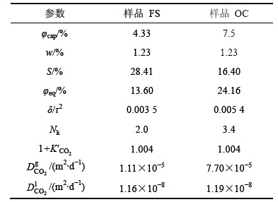
����̼������Ļ������Լ�������90 d��������ڲ�ëϸ��϶�ʺ�ʪ�����Ѿ���������ȶ�״̬��������Ӧ�IJ��Խ����ȷ������̼��������̼�������ֵ������������õļ���������������1��
3.1.2 ������̼���䷽�̵�����ָ�ʽ
�����eq(1-S+H��S)=a1, ����ʽ(3)����ͬʱ����a1���õ����µ���������ƫ�ַ�����ʽ��
 (28)
(28)
����Crank-Nicolson��ʽ���ȶ��Ժ������ԣ�������Ȼ����������̼�ڻ������д��䷽�̵�Crank- Nicolson��ʽ���ڵ�(xi, tn+��/2)������ʽ(28)��������ռ��ʱ��ȷ����ֱ�ΪM��N���ռ䷽��h=0.6/M��ʱ�䷽����=t/N�����ォ�������������ϵ���ֱ�ٶ�Ϊp��q���õ�
 (29)
(29)
��ʽ(29)����Ϊ

 ��
��
 ��
��
 (30)
(30)
��1 ����̼����ֵ�����еIJ���
Table 1 Calculating parameters of concrete carbonation
3.1.3 ��ֵ������
����Matlab���Ա�̶Լ�������������CO2���䷽�̵IJ�ָ�ʽ(30)������ֵ���㣬ͼ 1��ʾΪ����̼����������ƷFS������CO2Ũ�ȵ�ʱ�շֲ�ͼ��ͼ1(a)��ʾΪȫ��Ũ������ķֲ�ͼ��ͼ1(b)��ʾΪ������Ũ�ȵ�ʱ�շֲ������
��ͼ1(a)���Կ���������CO2�ڻ�������ƷFS�еķֲ����ַdz����Եķ����Էֲ���������ɢ��ʼ��ľ���ԽԶ������CO2��Ũ��Խ�ͣ�����̼��ʱ����ӳ����������ڲ�CO2Ũ�ȵ�Ҳ���ֳ������Ե����ӡ���������CO2Ũ�ȵķֲ���ȷ������̼����Ʒ�ڲ�̼ͬ������ʱ��̼�����(pH=11��)����ͼ1(b)��ʾ������������CO2Ũ�ȵķֲ����ߡ��ɼ�������̼���������̼�����ڵ��ӳ����ֳ����Ե��������ƣ�����Ҳ��̼��ǰ�������Ͽ죬̼��������Խ�����
�����������㷽�����Ի�������ƷOC����ͬ�����µļ���̼����Ƚ����˼��㣬ͼ2��ʾΪ��Ӧ������CO2Ũ��ʱ�շֲ��������ȷ����̼����ȵ���Ũ�ȼ�������
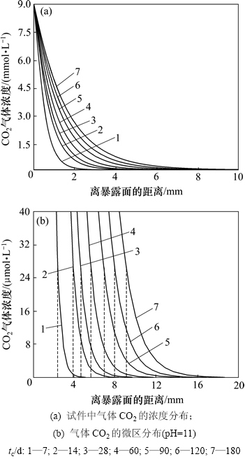
ͼ1 ��ƷFS����̼����ȵ���ֵ������
Fig. 1 Calculating results of accelerated carbonation depth of FS
��ͼ2(a)���Կ���������CO2�ڻ�������ƷOC�е�ʱ�շֲ�������������ƷFS����һ�µģ��������Եķ����Էֲ���������ͼ2(b)��ʾ����Ũ�ȷֲ������������ƷOC�ļ���̼����ȱ仯����Ҳ��ǰ�������Ͽ죬��������������
3.2 ��ֵ���������������ıȽ�
Ϊ����֤�����۽ṹ������̼��ģ����ֵ���㷽�����������ȷ�ԣ��ֽ����ϻ�������ƷFS��OC����̼����Ȳ����������ֵ���������бȽϣ������ͼ 3��
��ͼ3���Կ�������ƷFS��OC����̼�������ֵ����������������ʱ��ı仯���ƻ�����ͬ����̼ͬ�����ڶ��ߵ���ֵ����ֵ��Ϊ0.95 mm���Ƚ�ȷ�ط�ӳ�˻������ڼ���̼�������µ�̼����չ�����������ƷOC�Ŀ�϶�ʽϴ�������Ч��϶��Ҳ���Ը�����ƷFS�����������ʪ����ͬ����������ƷOC��ˮ�̶ȵͣ������ƷOC��CO2��Ч��ɢϵ��Ҫ���Ը�����ƷFS��Ч��ɢϵ���ϸߡ���Ҳ����ͬ��̼��������ƷOC�ļ���̼����Ⱦ�������ƬFS�ļ���̼����ȵ�ԭ��
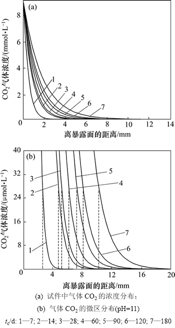
ͼ2 ��ƷOC����̼����ȵ���ֵ������
Fig. 2 Calculating results of carbonation depth of OC
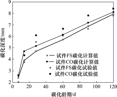
ͼ3 ����̼�������ֵ���������������ıȽ�
Fig. 3 Comparison of simulated data with experimental one
4 ����
1) ������Ч������������˻��ڵ�Ч��϶�ʺ�̼����Ӧ��������Ӱ���CO2Ũ�ȷֲ�ģ�͡��ɻ�����̼�������п�϶��Һ�еĵ绯ѧ��Ӧ���ܽ����ƽ������������˻�������϶��ҺpH�ļ��㷽�̡�
2) ������CO2���䷽�̵�Crank-Nicolson����ָ�ʽ������matlab��̼����˲��Ӻ�δ���ӿ�������ϵĵ�ˮ���Ȼ������ڼ���̼�������µ�CO2Ũ��ʱ�շֲ��������˲�̼ͬ������ʱ��̼����ȡ�
3) ͨ���Լ��������������ıȽϷ���������ȷ�������������Ի�����̼��ģ�Ϳ��ԺܺõضԻ�����̼����������Ԥ�⡣
�ο����ף�
[1] Page C L, Treadaway K W J. Aspects of the electrochemistry of steel in concrete[J]. Nature, 1982, 297(13): 109-115.
[2] Saetta A V, Votaliani R V. Experimental investigation and numerical modeling of carbonation process in reinforced concrete structures Part ��: Theoretical formulation[J]. Cement and Concrete Research, 2004, 34(2): 571-579.
[3] Bary B, Sellier A. Coupled moisture-carbon dioxide calcium transfer model for carbonation of concrete[J]. Cement and Concrete Research, 2004, 34(10): 1859-1872.
[4] Wu R, Liao Q, Zhu X, et al. A fractal model for determining oxygen effective diffusivity of gas diffusion layer under the dry and wet conditions[J]. International Journal of Heat and Mass Transfer, 2011, 54(2): 4341-4348.
[5] Papadakis V G, Vayenas C G. Experimental investigation and mathematical modeling of the concrete carbonation problem[J]. Chemical Engineering Science, 1991, 46(5/6): 1333-1338.
[6] Saetta A V, Votaliani R V. Experimental investigation and numerical modeling of carbonation process in reinforced concrete structures. Part ��: Practical application[J]. Cement and Concrete Research, 2005, 35(5): 958-967.
[7] Meier S A, Peter M A, Muntean M B. Dynamics of the internal reaction layer arising during carbonation of concrete[J]. Chemical Engineering Science, 2007, 62(4): 1125-1137.
[8] Isgor O B, Razaqpur A G. Finite element modeling of coupled heat transfer, moisture transport and carbonation process in concrete structures[J]. Cement and Concrete Composites, 2004, 26(1): 57-73.
[9] Muntean A, Bohm M. A moving-boundary problem for concrete carbonation: Global existence and uniqueness of weak solutions[J]. Journal of Mathematical Analysis and Applications, 2009, 360(1): 234-251.
[10] Tian L, Chen J G, Zhao T J. Durability of lining concrete of subsea tunnel under combined action of freeze-thaw cycle and carbonation[J]. Journal of Wuhan University of Technology (Mater Sci Ed), 2012, 27(4): 779-782.
[11] Younsi A, Turcry P, Roziere E, et al. Performance-based design and carbonation of concrete with high fly ash content[J]. Cement and Concrete composites, 2011, 33(2): 993-1000.
[12] Torgal F P, Miraldo S, Labrincha J A, et al. An overview on concrete carbonation in the context of eco-efficient construction: Evaluation, use of SCMs and/or RAC[J]. Construction and Building Materials, 2012, 36(4): 141-150.
[13] Collin M, Rasmuson A. A comparison of gas diffusivity models for unsaturated porous media[J]. Soil Science Society of America Journal, 1988, 52(3): 1559-1565.
[14] Jellick G J, Schnabel R R. Evaluation of a field method for determining the gas diffusion coefficient in soils[J]. Soil Science Society of America Journal, 1986, 50(2): 18-23.
[15] Jin Y, Jury W A. Characterising the dependence of gas diffusion coefficient on soil properties[J]. Soil Science Society of America Journal, 1996, 60(5): 66-71.
[16] Currie J A. Gaseous diffusion in porous media Part 3: Wet granular materials[J]. British Journal of Applicable Physics, 1961, 12(11): 275-281.
[17] ��־��, ��ΰ. ��ֽ��Ѷۻ��ٽ����ҺpHֵ������Ļ�����̼������ģ��[J]. ������ѧ��, 2007, 35(7): 899-903.
LIU Zhiyong, SUN Wei. Concrete carbonation model related to pH value of pore solution for Steel bar deprassiviation[J]. Journal of the Chinese Ceramic Society, 2007, 35(7): 899-903.
[18] Song H W, Kwon S J, Byuan K J, et al. Predicting carbonation in early-aged cracked concrete[J]. Cement and Concrete Research, 2006, 36(5): 979-989.
[19] Ishida T, Maekawa K, Soltani M. Theoretically identified strong coupling of carbonation rate and thermodynamic moisture states in micropores of concrete[J]. Journal of Advanced Concrete Technology, 2004, 2(2): 213-222.
[20] Houst Y F, Wittmann F H. Influence of porosity and water content on the diffusivity of CO2 and O2 through hydrated cement paste[J]. Cement and Concrete Research, 1994, 24(6): 1165-1176.
[21] BA Mingfang, QIAN Chunxiang. Effects of tensile stress on carbonation of multilevel concrete with low water-binder ratio[J]. Advanced Science Letters, 2011, 4(4/5): 1787-1789.
(�༭ ����ƽ)
�ո����ڣ�2014-07-10�������ڣ�2014-10-16
������Ŀ(Foundation item)��������Ȼ��ѧ����������Ŀ(51308308)��ˮ����ˮ��ѧ��ˮ�����ص�ʵ���ҿ����о�����������Ŀ(YK914015) (Project(51308308) supported by the National Natural Science Foundation of China; Project(YK914015) supported by the Key Laboratory of Water Science and Engineering of Ministry of Water Resources)
ͨ�����ߣ�Ǯ���㣬��ʿ�����ڣ����¸�����ˮ��������о���E-mail: cxqian1966@126.com
ժҪ�����ڶ�����̼�����ڻ��������Ĵ�����ƺ���Ч�������ۣ�������ǵ�Ч��϶�ʺ�̼����Ӧ��������(1+K��CO2)Ӱ��ķ����Զ�����̼����ģ�ͣ���������ֵĸ�ʽ����������ж�����̼Ũ�ȷֲ���ʱ�շֲ���������������Ļ�������϶��ҺpH�ļ��㹫ʽ��ȷ���������ڲ�̼ͬ�����ڵ�̼���̶ȡ�ͨ���Ի���������̼������������ֵ�������ĶԱȷ������о��������������̼����ȼ���������������ʱ��ı仯���ƻ�����ͬ��������̼ͬ������ʱ���ߵ���ֵ�����Ϊ0.95 mm����֪��������ϸ�۳߶��Ͽ���̼����ӦӰ��Ļ�����̼��ģ�Ϳ��ԺܺöԵ�ˮ���Ȼ�������̼������������з�����Ԥ�⡣
