
J. Cent. South Univ. Technol. (2010) 17: 868-872
DOI: 10.1007/s11771-010-0569-2![]()
Simulation of quasi-dimensional model for diesel engine working process
QI Kun-peng(������), FENG Li-yan(������), LENG Xian-yin(������),
TIAN Jiang-ping(�ュƽ), LONG Wu-qiang (¡��ǿ)
School of Energy and Power Engineering, Dalian University of Technology, Dalian 116024, China
? Central South University Press and Springer-Verlag Berlin Heidelberg 2010
Abstract:
In order to satisfy the demand of validity and real time operating performance of diesel engine model used in hardware-in- the-loop simulation system, a simplified quasi-dimensional model for diesel engine working process was proposed, which was based on the phase-divided spray mixing model. The software MATLAB/Simulink was utilized to simulate diesel engine performance parameters. The comparisons between calculated results and experimental data show that the relative error of power and brake specific fuel consumption is less than 2.8%, and the relative error of nitric oxide and
Key words:
1 Introduction
The hardware-in-the-loop simulation system of diesel engine [1-2] is composed of the hardware of diesel engine control system and the simulation model for diesel engine working process running in the computer. With the aid of hardware-in-the-loop simulation system, many expensive and time-consuming tests are replaced by utilization of the simulation model for diesel engine working process, and the development period of diesel engine control system is largely reduced.
Currently, the quasi-dimensional model for diesel engine working process is one of the most popular models applied to simulating the diesel engine working process and its central part is the spray mixing model. Varieties of quasi-dimensional models for diesel engine working process have been proposed during past decades [3-9]. Although these models have different organizations and computational methods, all of their central spray mixing models were developed on the basis of one of the three classic spray mixing models, which were called as fuel droplets evaporation model [3-6], transient gaseous flow model [7-8] and two-phase flow evaporation model [9]. In the fuel droplets evaporation model, combustion was assumed to be controlled by evaporation rate. Therefore, atomization process as well as evaporation process of fuel droplets was taken into account. Since the spray was divided into a large number of zones and evaporation rate of fuel droplets had to be calculated in each time step, the calculation with the fuel droplets evaporation model was very time-consuming. In the transient gaseous flow model, only the gaseous phase fuel existed in the combustion chamber due to the high pressure in it which caused the fuel droplets evaporated instantaneously, thus the combustion was determined by the mixing of fuel vapor and fresh air. Because the spray was simplified as a gaseous spray in this model, the computation of model was simpler, but the instantaneous evaporation of the fuel injected into the combustion chamber was not quite accurate. In the two-phase flow evaporation model, the evaporation of the fuel droplets was considered and the movement between the fuel droplets and entrained fresh air was neglected. It was assumed that the fuel in one combustion zone became approximated isoconcentration after some time and the two-dimensional flow was simplified as a one- dimensional flow. But the model was still complex for fuel droplets evaporation computation although the spray mixing process was simplified.
In this work, to meet the requirements of the validity and real time operating performance of diesel engine model used in hardware-in-the-loop simulation system, a phase-divided spray mixing model was developed to calculate the fuel-air mixing process in order to simplify the quasi-dimensional model for diesel engine working process. Additionally, the influence of parameters in calculation of fresh air entrainment on the prediction precision of performance parameters in diesel engine simulation model was analyzed.
2 Modeling of quasi-dimensional model for diesel engine working process
2.1 Phase-divided spray mixing model
Experimental results in Ref.[10] showed that the fuel injected into combustion chamber experienced two phases: the fuel droplets and the gaseous fuel-air mixture. The fuel droplets only existed around the nozzle. With the evaporation of the fuel droplets and the diffusion of spray, the fuel droplets became gaseous in short time and the fuel-air mixture formed. Based on this experimental phenomenon, a phase-divided spray mixing model was developed in this work. In this phase-divided spray mixing model, the fuel in combustion zones was liquid during break-up period and became gaseous after break-up time. The fresh air began to entrain into the combustion zones after break-up time and the two- dimensional flow was simplified as a one-dimensional flow.
The basic assumptions in the phase-divided spray mixing model as follows: (1) The combustion chamber is divided into an air zone A and many combustion zones Bi that are made up of the fuel injected into combustion chamber, the fresh air entrained into the zone, and the combustion products at each calculation time step. (2) During break-up period, the injected fuel atomizes and evaporates. No fresh air is entrained into combustion zones in this period, and fresh air entrainment is assumed to start after break-up time. The fuel-air mixture becomes isoconcentration after break-up time, and the two-dimensional flow is simplified as a one-dimensional flow. (3) The amount of fresh air entrained into the combustion zone is calculated based on the fuel momentum when it is injected and the momentum remains the same during mixing process. (4) Fuel is mixed by the fresh air entrainment according to the equivalent fuel air ratio in combustion zones, and partial burning is neglected here. (5) There is no fresh air entrained into combustion zone after the fuel in this zone is burnt out. Fig.1 shows the schematic diagram of zone

Fig.1 Schematic diagram of zone division of phase-divided spray mixing model
division of the phase-divided spray mixing model. The boundaries of B1, B2, B3, and B4 are clearly shown as isochrones in the figure, since the fuel in these zones has experienced break-up process and mixed with fresh air. On the contrary, the fuel in other zones is still undergoing break-up process and their boundaries cannot be shown.
2.2 Quasi-dimensional model for diesel engine working process
The quasi-dimensional model for diesel engine working process is divided into six sub-models, namely compression sub-model, combustion sub-model, expansion sub-model, exhaust sub-model, inlet and outlet valve overlap sub-model and intake sub-model. The simulation results, which include instantaneous data such as pressure, temperature, mass and performance parameters such as power, brake specific fuel consumption (BSFC), nitric oxide and soot emissions, are obtained by solving the energy conservation equations, the mass conservation equations and the ideal gas state equations [11-14]. In the quasi-dimensional model, the combustion sub-model is divided into break-up time calculation, fresh air entrainment calculation, ignition delay period calculation, heat transferring calculation, thermo- dynamics calculation, combustion products calculation and emissions calculation. The break-up time calculation and fresh air entrainment calculation are formulated in detail in the following sections.
2.2.1 Break-up time calculation
The break-up time (tb) is calculated according to HIROYASU equation [15], but with different definition on the fuel phase after break-up time. In the phase- divided spray mixing model, it is assumed that the fuel droplets experience atomization, gasification, and become gaseous after break-up time.
![]() (1)
(1)
where ��l is the density of liquid fuel at the exit of the nozzle hole; d0 is the diameter of the nozzle hole; ��a is the density of fresh air in the cylinder; pinj is the fuel injection pressure; and pa is the in-cylinder pressure.
2.2.2 Fresh air entrainment calculation
The quantity of fresh air entrained into combustion zone is calculated in accordance with the momentum conservation principle [9]:
![]() (2)
(2)
![]() (3)
(3)
where mfi is the ith zonal fuel quantity; uoi is the ith zonal initial velocity at the exit of the nozzle hole; maij is the quantity of fresh air entrained into the ith zone from start time when the fuel is injected into the combustion chamber to the jth calculation time step; uj is the ith zonal average velocity during the jth calculation time step; and ��maij is the theoretical quantity of fresh air entrained into the ith zone during the jth calculation time step.
When the flame occurs in a combustion zone, there is a reduction of the fresh air entrainment rate in the model. The quantity of fresh air entrained into a burning combustion zone is given by
![]() (4)
(4)
where ![]() is the factual fresh air quantity in the ith zone during the jth calculation time step; and ca is the correct coefficient representing the effect of flame on fresh air entrainment.
is the factual fresh air quantity in the ith zone during the jth calculation time step; and ca is the correct coefficient representing the effect of flame on fresh air entrainment.
3 Simulation of quasi-dimensional model for diesel engine working process
MATLAB/Simulink was utilized to simulate the quasi-dimensional model for diesel engine working process. With the aid of MATLAB/Simulink, it is easy for users to understand the antitype of system quickly, adjust the parameters of simulation system conveniently and improve the development efficiency of simulation system obviously.
Experimental data were obtained from the 1135 naturally aspirated diesel engine for comparison with the calculated results. The specifications of the diesel engine are listed as follows: the cylinder bore is 135 mm, the stroke is 150 mm, the connecting rod length is 265 mm, the compression ratio is 17:1, the displacement volume is 2.147 L, the rated power is 14.7 kW, and the rated rotation speed is 1 500 r/min.
3.1 Real time operating performance of model
Because the computational cost of spray mixing process in the phase-divided spray mixing model is largely decreased comparing with that of other spray mixing models, the real time operating performance of simulation system is greatly improved. The average computational time for one working process of the simulation model developed in this work is 36 s in the computer equipped with a CPU of AMD 2500+1.83 GHz and 512 M memory.
3.2 Validation of model
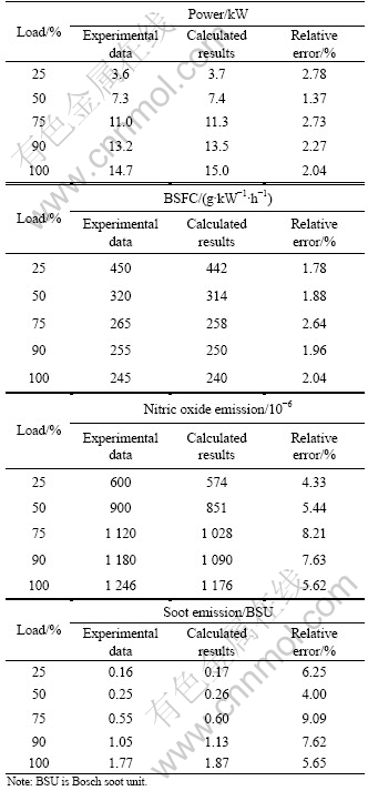
Fig.2 shows the comparisons of calculated results and experimental data of in-cylinder pressure and heat release rate in rated condition. The comparisons of calculated results and experimental data of diesel engine performance parameters at rated speed in different load conditions are shown in Table 1.

Fig.2 Comparisons of calculated results and experimental data of in-cylinder pressure (a) and heat release rate (b) in rated condition
Fig.2(a) shows that the calculated maximum pressure is 7.048 MPa at 11? ATDC (after top dead center), corresponding to the experimental maximum pressure of 6.962 MPa at 12? ATDC and the two in-cylinder pressure curves are consistent with each other in rated condition. Fig.2(b) indicates that the calculated and experimental heat release rates show good agreement in rated condition. The saw tooth in the curve of calculated heat release rate is due to the variation of zones involved in combustion and different quantities of the fuel in each zone participated in combustion during each calculation step. Also, it can be observed from Table 1 that the calculated results and experimental data agree well. The relative error of power and BSFC between calculated results and experimental data is less than 2.8%, and the relative error of nitric oxide and soot emissions between calculated results and experimental data is less than 9.1% at rated speed in different load conditions. These results indicate that the assumptions in phase-divided spray mixing model are reasonable and the prediction of diesel engine performance parameters is accurate enough, which means that the quasi- dimensional model for diesel engine working process is validated to be applied to the hardware-in-the-loop simulation system.
Table 1 Comparisons of calculated results and experimental data of diesel engine performance parameters at rated speed in different load conditions
3.3 Influence of nozzle flow coefficient on model��s prediction precision
Because the fuel in zone Bi is fully gasified and the spray mixture for combustion is formed after break-up time in phase-divided spray mixing model, the combustion process is controlled by the calculation of fresh air entrainment in quasi-dimensional model for diesel engine working process, which has significant effect on the prediction precision of the model��s performance parameters.
Eq.(2) shows that the quantity of fresh air entrained into combustion zone is controlled by the zonal initial velocity at the exit of the nozzle hole in the condition of other parameters unchanged. The initial velocity can be calculated by [9]
![]() (5)
(5)
where cd is the nozzle flow coefficient.
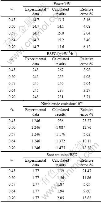
It can be seen from Eq.(5) that the nozzle flow coefficient has great influence on the simulation of fuel-air mixture formation, combustion process, and further on the calculated results of the whole diesel engine working process. Therefore, the selection of this coefficient largely affects the prediction precision of the model��s performance parameters. When the nozzle flow coefficient becomes bigger, the initial momentum at the exit of the nozzle hole is larger and more quantity of fresh air is entrained into combustion zone. As a result, the quantity of fuel-air mixture increases and the combustion rate is faster. Table 2 shows the influence of different nozzle flow coefficients on the prediction precision of the model��s performance parameters in rated condition.
From Table 2, it is obtained that both the fuel-air mixing rate and the combustion rate become lower when the nozzle flow coefficient is smaller. This leads to the decrease of cylinder pressure and temperature during combustion process. Accordingly, the error of performance parameters between calculated results and experimental data is larger. When the nozzle flow coefficient is increased, the initial momentum at the exit of the nozzle hole becomes larger. As a result, higher cylinder pressure and temperature are caused by faster fuel-air mixing rate as well as combustion rate, and the error of performance parameters between calculated results and experimental data diminishes. There is an optimum value of nozzle flow coefficient according to different conditions as shown in Table 2, and if the coefficient is larger than the optimum value, the initial momentum at the exit of the nozzle hole becomes too large. Consequently, the combustion becomes very fierce and the calculation error enlarges. In one word, the model��s prediction precision of performance parameters is improved by proper selection of nozzle flow coefficient according to the factual combustion process during the simulation of different conditions.
Table 2 Influence of nozzle flow coefficient on prediction precision of model��s performance parameters in rated condition
4 Conclusions
(1) Since the fuel-air mixing process is simplified in the phase-divided spray mixing model, the calculation cost of mixing process is reduced in contrast with that of other spray mixing model, and real time operating performance is greatly improved.
(2) Based on the phase-divided spray mixing model, the quasi-dimensional model for diesel engine working process is developed and validated by the comparison between calculated results and experimental data.
(3) It is important to select the appropriate value of nozzle flow coefficient to ensure the model��s prediction precision.
References
[1] SHAYLER P J, ALLEN A J, ROBERTS A L. Running real-time engine model simulation with hardware-in-the-loop for diesel engine development [C]// SAE Technical Paper Series. Warrendale: Society of Automotive Engineers, Inc, 2005: 2005-01-0056.
[2] ALLMENDINGER K, GUZZELLA L, SEILER A, LOFFELD O. A method to reduce the calculation time for an internal combustion engine model [C]//SAE Technical Paper Series. Warrendale: Society of Automotive Engineers, Inc, 2001: 2001-01-0574.
[3] HOUNTALAS D T, KOUREMENOS D A, MAVROPOULOS G C, BINDER K B, SCHWARZ V. Multi-zone combustion modeling as a tool for DI diesel engine development-application for the effect of injection pressure [C]// SAE Technical Paper Series. Warrendale: Society of Automotive Engineers, Inc, 2004: 2004-01-0115.
[4] PARIOTIS E G, HOUNTALAS D T. Validation of a newly developed quasi-dimensional combustion mode-application on a heavy-duty DI diesel engine [C]// SAE Technical Paper Series. Warrendale: Society of Automotive Engineers, Inc, 2004: 2004-01-0923.
[5] UDAYAKUMAR R, ANAND M S. Multi-zone combustion model for a four-stroke direct injection diesel engine [C]// SAE Technical Paper Series. Warrendale: Society of Automotive Engineers, Inc, 2004: 2004-01-0921.
[6] DOHOY J, DENNIS N A. Multi-zone DI diesel spray combustion model for cycle simulation studies of engine performance and emissions [C]// SAE Technical Paper Series. Warrendale: Society of Automotive Engineers, Inc, 2001: 2001-01-1246.
[7] KULESHOY A S. Multi-zone DI diesel spray combustion model for thermodynamic simulation of engine with PCCI and high EGR level [C]// SAE Technical Paper Series. Warrendale: Society of Automotive Engineers, Inc, 2009: 2009-01-1956.
[8] KULESHOY A S. Use of multi-zone DI diesel spray combustion model for simulation and optimization of performance and emissions of engines with multiple injection [C]// SAE Technical Paper Series. Warrendale: Society of Automotive Engineers, Inc, 2006: 2006-01- 1385.
[9] JIN Guo-dong. A simplified vaporizing and mixing model for diesel spray two-phase flow [J]. Transactions of CSICE, 1986(2): 143-149. (in Chinese)
[10] CHIU W S, SHAHED S M, LYN W T. A transient spray mixing model for diesel combustion [C]// SAE Technical Paper Series. Warrendals: Society of Automotive Engineers, Inc, 1976: 760128.
[11] JIANG De-ming. Combustion and emission of internal combustion engine [M]. Xi��an: Xi��an Jiaotong University Press, 2001: 27-60, 423-575. (in Chinese)
[12] XIE Mao-zhao. Combustion calculation of internal combustion engine [M]. Dalian: Dalian University of Technology Press, 2005: 65-84, 137-168. (in Chinese)
[13] ZHOU Nai-jun, PEI Hai-ling, ZHANG Jia-qi, CHEN Hong-de. Mathematic models for thermodynamic process of rotary combustion engine [J]. Journal of Central South University: Science and Technology, 2008, 39(2): 284-289. (in Chinese)
[14] GONG Jin-ke, LIU Meng-xiang, LIU Xiang-ling, TAN Kai, ZHOU Li-ying. Diesel engine modeling and simulation using software simulink [J]. Journal of Hunan University: Natural Sciences Edition, 2002, 29(4): 38-41. (in Chinese)
[15] HIROYASU H, KADOTA T, ARAI M. Development and use of a spray combustion modeling to predict diesel engine efficiency and pollutant emission [J]. Japan Society of Mechanical Engineers, 1983, 26: 569-583.
Foundation item: Project(2006A10GX059) supported by the Science and Technology Plan of Dalian, China
Received date: 2009-08-28; Accepted date: 2009-12-17
Corresponding author: LONG Wu-qiang, Professor; Tel: +86-13889538768; E-mail: longwq@dlut.edu.cn
(Edited by YANG You-ping)
