
Trans. Nonferrous Met. Soc. China 29(2019) 569-578
Characterization of residual stresses and microstructural features in an Inconel 718 forged compressor disc
Xiao-yan XU1, Xiang-dong MA2, Hong WANG3, Zhang YE4, Jian-wei CHANG1, Yao XU1, Guang-ai SUN3, Wei-jie LU5, Yu-kui GAO4
1. Commercial Aircraft Engine Co., Aero Engine Corporation of China, Shanghai 201108, China;
2. Shenzhen Wedge Central South Research Institute Co., Ltd., Shenzhen 518045, China;
3. Key Laboratory of Neutron Physics and Institute of Nuclear Physics and Chemistry, China Academy of Engineering Physics, Mianyang 621999, China;
4. School of Aerospace Engineering and Applied Mechanics, Tongji University, Shanghai 200092, China;
5. State Key Laboratory of Metal Matrix Composites, Shanghai Jiao Tong University, Shanghai 200240, China
Received 10 January 2018; accepted 19 June 2018
Abstract:
Residual stress plays an important part in fabricating commercial aero engine Inconel 718 components for their fatigue properties, reliability and durability. Due to the limitation of Chinese neutron diffraction instrument and lack of test practice and specifications, there is little systematic research on the residual stress of forged compressor disc. X-ray diffraction and neutron diffraction methods were used to measure the residual stress of Inconel 718 forged discs at the surface and in the interior, respectively. Scanning electron microscope and transmission electron microscope were used to characterize the microstructural features. The residual stress state at the disc is in near-surface compression, balanced by tension within the disc core. However, the surface residual stress of disc depends more on the rough machining than on the forging process. Also, the dislocation densities increase with decreasing distance to the surfaces of disc, and the residual stress accelerates dislocation generation and dynamic recrystallization.
Key words:
neutron diffraction; X-ray diffraction; residual stress; Inconel 718; compressor disc;
1 Introduction
Inconel 718 high temperature superalloy is the main material used in aero engine which has high strength, resistance to oxidation, good high temperature fatigue and creep properties at 700 ��C. Aero engine components such as turbine disc, blade, case, shaft, seal and fastener are all fabricated by Inconel 718. Residual stress introduced during the fabrication of Inconel 718 components would decrease the fatigue properties, and have a negative impact on the safety, reliability and durability of the commercial aero engine. Residual stress nowadays becomes the key technology and critical parameter on manufacturing aero engine blade, disc and rotors. For the past few years, new materials and processes have been developed to fabricate engine components in NASA, Siemens, and Rolls Royce, and the residual stress measurement becomes a request for critical components.
Residual stresses are self-equilibrating stresses within a stationary solid body when no external forces are applied [1]. This kind of stresses is difficult to measure, hard to predict but gives rise to unexpected failure. Residual stresses can be caused either by fabrication, joining, assembly, heat or surface treatment, service use, or by a complex combination of all of them. In many testing methods, X-ray diffraction and neutron diffraction are nondestructive and noncontact measurements to map the stress field of the actual components. The penetration depth of X-ray is only several micrometers, which makes this technology suitable to detect the surface stress of the samples. Neutron provides deeper penetrations, which can probe into large components, and it can also reveal the strain heterogeneities within the material [2].
X-ray diffraction is already widely used in residual stress measurement and with removing the surface material, the test depth can also extend to a few millimeters. Neutron diffraction has been used for residual stress measurement on single crystal Ni base superalloy turbine blade [3]. SKOURAS et al [4] measured the residual stress of a ferrite steel/Inconel 625 superalloy dissimilar metal weldment by neutron diffraction. WOO et al [5] used neutron diffraction to detect that the significant tensile stresses (90% yield strength) occur along the weld centerline near the top surface on ferrite steel weld. By observing and analyzing the variation of the peak shifting, broadening and asymmetry of the diffraction peak, stacking fault energy and dislocation energy can be determined. These parameters are quantitatively correlated to the yield strength, serrated flow and strain hardening during tensile deformation [6].
The through-thickness residual stresses of full scale nickel base superalloy aero engine compressor disc were measured and the residual stress evolution during the forging process of Inconel 718 was studied. TIN et al [7] used simulation and neutron diffraction measurements to study the residual stress of nickel base superalloy discs throughout the entire manufacturing route, including vacuum induction melting, vacuum arc melting, homogenization heat treatment, cogging, forging, final heat treatment and machining. RIST et al [8] did a series of neutron diffraction measurements to determine the residual stress within a forged then water-quenched Inconel 718 aero engine compressor disc, and compared with thermal mechanical finite element model. They found that the general residual stress in the disc is near-surface compression, balanced by tensile within the disc interior. CIHAK et al [9] also studied the residual stress distribution on hot-forged and water-quenched compressor disc made of Inconel 718 by neutron diffraction and simulation, and they obtained the similar results with Ref. [8]. DYE et al [10] used the finite element method to analyze 2 cm-in-diameter small cylindrical bars of Inconel 718 quenched in oil, water, and air, and validated against neutron diffraction measurements of the three-dimensional stress field made at the cylinder midsection.
A lot of research was done on Inconel 718 superalloy, especially the critical process on fabricating Inconel 718 parts, which made the performance of Inconel 718 forged disc increased and meet the research requirement of Chinese aero engine. Due to the limitation of neutron diffraction equipment and lack of measurement practice, there is not much systematic research conducted on residual stress generated in the Inconel 718 forged disc. In this work, residual stresses of Inconel 718 forged compressor discs generated by two forging processes (speed control die forging and normal die forging) were compared by X-ray diffraction and neutron diffraction measurements. The influence of forge speed on disc core residual stress was discussed, and the distribution of residual stress over the disc was illustrated. Meanwhile, the microstructural features of Inconel 718 forged compressor disc were characterized with scanning electron microscope (SEM) and transmission electron microscope (TEM).
2 Experimental
2.1 Materials and forging process
The studied material of compressor disc was nickel base Inconel 718 superalloy. The major chemical compositions of Inconel 718 superalloy were determined by fluorescence spectrophotometer as 19.28% Cr, 52.59% Ni, 5.20% Nb, 3.10% Mo, 1.00% Ti, 0.73% Al, and balanced Fe (mass fraction). The Inconel 718 superalloy was vacuum arc remelted (VAR) for three times to d220 mm. Two forging processes were used for forging the compressor discs to optimize the process with less residual stress generated. Inconel 718 material billet was heated in the furnace to 1010 ��C for 100 min, and the fixture tools were heated to 250 ��C. The billet was transferred from furnace to die within 30 s, and pre-forged from 1010 to above 930 ��C. The deformation of the billet forging was more than 50%, and then near isothermal forging was used for the two kinds of processes. The blank was heated to 1010 ��C, and the close die was heated to 300 ��C and kept for more than 12 h. The closed die forging started at 1010 ��C and ended above 930 ��C with more than 40% deformation. The press speed of normal forging process is 4-6 mm/s, and the press speed of speed control forging process is 2-3 mm/s. Then, the discs were heat-treated and roughly machined for the following test. The heat treatment process is 950-980 ��C for 1 h, 720 ��C for 1 h, furnace cooled to 620 ��C for 8 h, and then air cooled.
2.2 X-ray diffraction
X ray diffraction was used to test the residual stress of the compressor disc less than 2 mm from the surface. Mn target was chosen for the X-ray diffraction test for Inconel 718 because of less error and higher accuracy than Cr and Cu target. The surface layer of the disc was removed by electropolishing, with voltage of 40 V and polishing time of 10 s. The electropolishing parameters can be adjusted by the depth of the removed material. The first electropolishing depth interval was 20 ��m, and with the depth increasing, the interval was increased from 20 to 200 ��m. The error of the electropolishing material removal is ��1 ��m. The X-ray diffraction parameters are given in Table 1.
Table 1 X-ray diffraction characteristics and measurement parameters conducted on Inconel 718

2.3 Neutron diffraction
The neutron diffraction experiments were conducted with residual stress neutron diffraction instrument (RSND) at China Academy of Engineering Physics. The RSND can provide 0.12-0.28 nm neutron wavelength for residual stress test which matches the diffraction plane spacing of the tested material. Neutron wavelength ��=0.1578 nm was used for this measurement based on the primary experiments, which can ensure the penetration depth and resolution ratio. Nickel base superalloy has a face center cubic (FCC) crystal structure, and its lattice constants are a=b=c=3.5238  with ��=��=��=90��. Diffraction plane (311) was chosen because its weak intergranular strain sensitivity and diffraction angle of 94.5�� which is close to diffraction angle of 90�� (geometric requirement) during the neutron diffraction residual stress measurement. Gauge volume is defined as the intersection of the incident beam and the diffraction beam. The test sample should be placed within the gauge volume, because only properties averaged over the whole gauge volume can be detected. The sample volume must be adjusted based on the received diffraction peak signal intensity to obtain distinct peak signal, accurate measurement and minor error. The detected count is also an important parameter during the residual stress measurement. Count is the number of neutrons that the detector received in a fixed time. Higher count and minor fluctuated diffraction peak should be chosen based on the comprehensive consideration of sample volume, neutron penetration path, diffraction time and measuring efficiency. The convincing diffraction peak intensity should be higher than 200 counts and the signal-to-noise ratio should be no less than 1:1. Based on the above parameter choosing principle, the neutron diffraction residual stress measurement parameters adopted in this measurement are given in Table 2.
The discs were placed on the sample stage, and two directions were chosen to measure the residual stress, which are radial and axial directions. The test positions are shown in Fig. 1(a) (axial direction) and Fig. 1(b) (radial direction). Figure 1(b) also indicates incident slit, scattered slit, jig and workbench.
Table 2 Neutron diffraction measurement parameters conducted on Inconel 718


Fig. 1 Axial direction (a) and radial direction (b) of neutron diffraction test
Different from X-ray diffraction, the residual stress calculation by neutron diffraction measurement needs lattice spacing d0 when the sample is under stress-free condition. The d0 value was determined by the following method: After all the positions were tested by RSND, the disc was sectioned to be 4 mm �� 4 mm �� 20 mm by wire electrode cutting to make sure that the composition and microstructure are the same with the sample before stress release treatment. Then, the specimen was annealed at 700 ��C for 90 min and furnace-cooled to room temperature. The lattice spacing measured by RSND with the same parameters on this specimen was defined as the stress-free d0.
The positions of X-ray diffraction and neutron diffraction on the Inconel 718 compressor discs are shown in Fig. 2. Gaussian fitting was used to analyze the peak profiles as suggested by international standard method [11].
2.4 Characterization
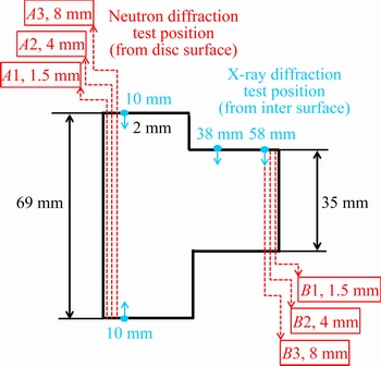
Fig. 2 X-ray diffraction and neutron diffraction measurement positions of Inconel 718 compressor disc
The microstructure of Inconel 718 compressor disc was observed using a NOVA NanoSEM 230 field emission SEM, and the samples were extracted from A cross-sectional line of compressor disc in Fig. 2. The SEM samples were cold mounted, ground, polished and then etched with a solution of 4 g CuSO4 + 20 mL HCl + 20 mL C2H5OH at room temperature. A JEM-2100 TEM was used to observe the strengthening phase ��" and determine the dislocation of superalloy along the thickness direction of A cross-sectional line of compressor disc. The TEM samples were sectioned to thin plates, mechanically polished to 100 ��m in thickness, and then twin-jet electro-polished using a solution of 33% HNO3 + 67% CH3OH at -25 ��C.
3 Results
3.1 Microstructure
The low magnification image of Inconel 718 forged compressor disc is shown in Fig. 3(a) which indicates a uniform microstructure. The high magnification image of Inconel 718 forged compressor disc is shown in Fig. 3(b) which contains �� grains as matrix, equilibrium �� phases, and a small amount of NbC inclusions. In addition, the Inconel 718 superalloy derives its in-service strength mainly from precipitation (below 900 ��C) of coherent intermetallic nanoscale phases: the niobium-rich body- centered tetragonal (BCT) ��" phase and, to a less extent, the aluminum-rich and/or titanium-rich face- centered cubic (FCC) ��' phase. The size and amount of ��' phase and carbide are influenced by quenching method and hot compression parameters [12,13].

Fig. 3 Low magnification (a) and high magnification (b) microstructures of forged Inconel 718 disc
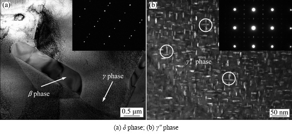
Fig. 4 TEM microstructures of forged Inconel 718 disc
Figure 4 shows the TEM microstructural features of �� phase and ��" phase in Inconel 718 forged compressor disc. It can be seen from Fig. 4(a) that �� phase is incoherent with �� matrix, which leads to relatively small alloy strengthening and adverse effect on ductility. However, precipitation of the orthorhombic �� phase is also important at hot-working temperatures above 900 ��C, where its presence can be used to control grain size through grain boundary pinning [14,15]. It can be seen clearly from Fig. 4(b) that the main strengthening ��" phase distributes perpendicularly and is coherent with �� matrix.
3.2 Stress-free lattice spacing
The d0 value has effect on residual stress measurement by neutron diffraction on nickel base superalloy [16]. The stress-free lattice spacings d0,hkl were measured using neutron diffraction after a complete annealing, and the results are given in Table 3. It can be seen that the average values of d0,hkl in two principal directions (radial and axial) with a small differences have a good agreement with the crystal structure parameters of Inconel 718 superalloy [17,18].
Table 3 Measurement results of stress-free lattice spacing d0,hkl

3.3 Neutron diffraction test results
The neutron diffraction measurement positions on the forged disc are shown in Fig. 2. Due to the large thickness of the disc (69 mm of A lines and 35 mm of B lines), residual stress on hoop direction is difficult to test (depth penetration). Therefore, only residual stress on radial and axial directions were tested. Figure 5(a) shows the residual stress distributions of line A1, A2 and A3 in radial direction and line A2 in axial direction. Figure 5(b) shows the residual stress distributions of line B1, B2 and B3 in radial direction and line B2 in axial direction. It is obvious that radial residual stress near the surface of disc (1.5 mm) demonstrates negative values (compressive stress), with A1 line showing around -200 MPa residual stress and B1 line showing around -50 MPa residual stress. When the test position moves into the core of the disc (4 and 8 mm), the radial and axial residual stresses all become positive (tensile stress). Especially, when the test position moves from surface (2.5 or 3.5 mm from surface) into interior, A2, A3 and B2, B3 lines all present a large stress increase. B2 line in axial direction even increases from compressive residual stress to 150 MPa tensile residual stress. These results may indicate that the surface of the disc has compressive residual stress and the core of the disc has tensile stress. A3 line in radial direction and B2 line in radial direction both show good symmetry, and all of the measured values show reasonable error.

Fig. 5 Radial and axial residual stresses versus distance to reference surfaces by neutron diffraction measurement
The experimental error of residual stresses was evaluated by the following equation [19,20]:

 (1)
(1)
where E is the elastic modulus, v is Poisson ratio, u(��) is the strain uncertainty, and
u(��)=cot(��)u(��) (2)
From Fig. 5, the experimental errors are from 7 to 27 MPa, much smaller than the tested values of residual stresses in compressor disc, which indicates the high accuracy of experimental results. Generally, large experimental errors are associated with less accessible parts of the compressor disc and longer effective diffraction path, although these are partially compensated by using longer data-acquisition time.
3.4 X-ray diffraction test results
The X-ray diffraction test positions on the forged disc are shown in Fig. 2, with a measuring depth of 2 mm. Three positions, 10, 38 and 58 mm, and two directions, radial and axial directions of neutron diffraction, were chosen from the overall surface. Figure 6(a) shows the residual stress versus distance from the surface of normal forging process by X-ray diffraction, and Fig. 6(b) shows that of the speed control forging process. The disc surface presents a large value of compressive stress (more than -800 MPa), because of the high residual stress generated by rough machining on the disc surface. After 50 ��m layer removal, the residual stress increases at first and then becomes almost constant down to 2 mm in depth. The residual stress values have large difference between radial and axial directions. So, the trend of residual stress depended on the distance to surface is not obvious. Generally speaking, the residual stresses of disc surface (up to 2 mm) are compressive stress, and vary from 0 to -400 MPa based on different positions.

Fig. 6 Radial and axial residual stresses versus distance to reference surfaces by X-ray diffraction measurement
4 Discussion
4.1 Residual stress distribution
Due to different penetration depths of X-ray diffraction and neutron diffraction, the Inconel 718 forged disc was tested both by X-ray diffraction (from the surface to 2 mm in depth) and neutron diffraction (more than 2 mm in depth). Because of the large gauge volume of neutron diffraction (2 mm��2 mm��4 mm), when the test position is 2.5 mm, the detector gathers the diffraction neutrons from 1.5 to 3.5 mm along the depth direction. Therefore, combining X-ray diffraction and neutron diffraction can provide a whole scale of residual stress variation from the surface to core of the Inconel 718 disc.
Figure 7 shows the residual stress distribution with X-ray diffraction and neutron diffraction measurement. Figure 7(a) shows the residual stress of line B3 for neutron diffraction and 58 mm for X-ray diffraction, where both measurements start at the same surface position (see Fig. 2). Except the surface residual stress induced from rough machining (-800 MPa), the near- surface residual stress increases from around -100 to 0 MPa down to 2 mm. The residual stress measured from 2.5 mm by neutron diffraction starts from 0 to around 100 MPa. It is really obvious that the residual stress near the disc surface displays a compressive stress and the inside of disc displays a tensile stress, which is consistent with Fig. 5. Figure 7(b) shows the residual stress of line A3 for neutron diffraction and 10 mm (from both top and bottom) for X-ray diffraction, the two positions are away from each other for 2 mm. The residual stress distribution trend of Fig. 7(b) is similar with Fig. 7(a), and both show compressive stresses near the surface and tensile stresses inside the disc.

Fig. 7 Residual stress of line B3 for neutron diffraction and 58 mm for X-ray diffraction (a), and residual stress of line A3 for neutron diffraction and 10 mm (from both top and bottom) for X-ray diffraction (b) (Both measurements are from normal process disc)
In other works, neutron diffraction measurement on forged and water-quenched Inconel 718 disc shows up to 600 MPa compressive residual stress on the surface, up to 400 MPa tensile residual stress in the core [7], and a magnitude of 400-500 MPa near the disc surface (compression) and at its core (tension) after forging and water quenching [8]. However, in this work, the surface residual compressive stress can be up to 250 MPa, the tensile stress in the core is up to 250 MPa, and the stress value is much lower. This could be due to the heat treatment which diminishes the residual stress of the Inconel 718 forged disc. The solution and aging during heat treatment can also decrease the residual stress inside the disc. The transition region from compression to tension is about 10 mm below the surface of the forged and quenched disc [8], while the transition region in Fig. 7 shows 2-3 mm below the surface in heat-treated disc.
4.2 Influence of forging process on residual stress
Two close die forging processes were used to press the Inconel 718 disc, and the difference of the two processes is press speed. Normal forging process has a press speed of 4-6 mm/s, and the press speed of speed control forging process is 2-3 mm/s. Figure 8(a) shows both the radial and axial residual stresses of line A2 of normal and speed control forging processes, and Fig. 8(b) shows residual stresses of the line B2. The residual stresses of speed control disc in Fig. 8(a) are around 50 MPa less than those of the normal process disc from 5 to 15 mm away from surface both in radial and axial directions. With the distance increasing, the residual stress difference of the two kinds of processes is decreased, especially in the core of the disc. The residual stress difference at line B2 is not obvious, probably because line B2 (35 mm) is thinner than line A (69 mm), which deforms more uniformly during the forging process, and therefore, the influence of press speed is not so distinct.
Figure 9 shows the surface residual stresses measured by X-ray diffraction by speed control and normal forging processed disc at different test positions. The residual stress of speed control forging processed disc and normal forging processed disc does not show similar trend on the three positions. Figure 9(a) shows higher compressive residual stress on the speed control disc surface than on the normal disc surface. However, the 38 mm test position (Fig. 9(b)) shows opposite results, and the 58 mm test position (Fig. 9(c)) shows almost the same results of residual stress values. From comparison, X-ray diffraction measurement on disc surface could not play an important role in differentiating speed control and normal forging process. This is probably because X-ray diffraction measurement on surface residual stress depends more on surface machining than neutron diffraction.

Fig. 8 Radial and axial residual stresses of normal and speed control forging processed disc
4.3 Influence of residual stress on microstructural features
Figure 10 shows the dislocation densities of line A of Inconel 718 compressor disc (by normal forging process) at different distances to the surface. It can be seen that dislocation densities decrease with increasing distance to the surface, which is consistent with the phenomenon in Fig. 7(b): higher residual stress results in higher amount of dislocations. Also, the dislocation density around �� phase or grain boundary is obviously much higher than that at intragranular, which indicates that dislocations tend to generate in high stress concentration region. LIN and PANG [21] used discrete dislocation simulation to predict the development of thermal residual stresses and thermal induced dislocations in metal matrix nanocomposites, and found that the dislocation density is higher in the interfacial region than in the rest of the matrix. With regard to Inconel 718 forged compressor disc, the dislocation is generated by dislocation climbing and pile-up during the forging process, and then subgrain boundary is formed subsequently through regular arrangement. Additionally, �� phases distributing along crystal boundary and dispersed ��" phase together affect the dislocation formation. High density dislocation is beneficial to the precipitation of the ��" phase from �� matrix. Meanwhile, stacking faults produced by ��" phase precipitation promote �� phase nucleation.

Fig. 9 Surface residual stresses by X-ray diffraction measurement of speed control and normal forging processed disc
Figure 11 shows the phases and orientation maps of Inconel 718 compressor disc (by normal forging process) at different distances to the surface. It can be found that the average grain size of Inconel 718 forged compressor disc at the surface (Fig. 11(a), approximately 2.26 ��m) is less than that in the core (shown in Fig. 11(c), approximately 4.58 ��m), probably because the following rough machining or a significant temperature gradient induces a large residual stress, which accelerates the dynamic recrystallization at the surface of compressor disc. Dynamic recrystallization leads to nucleation and generates new grains [22]. If the new grains formed by nucleation cannot grow up enough and are kept at ambient temperature, fine-grained structure forms. Moreover, higher residual stresses which result in higher density dislocations around �� phases or grain boundaries are also beneficial to the dynamic recrystallization. They tend to constitute dislocation tangling and cell structures, which can form subgrain boundaries by annihilation and recombination under further shear stress.
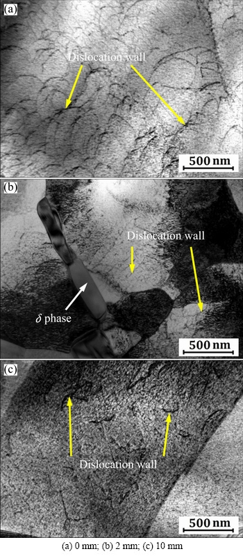
Fig. 10 Dislocation densities of line A at different distances to surface
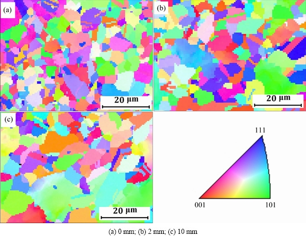
Fig. 11 Phases and orientation map of line A at different distances to surface
5 Conclusions
(1) X-ray diffraction measurement on Inconel 718 disc indicates that the surface residual stress is around -800 MPa, then increases and is stable at 0 to -400 MPa down to 2 mm. Neutron diffraction measurement indicates the compressive residual stress of near surface and tensile residual stress of center.
(2) The residual stresses of speed control forging processed disc are 50 MPa less than those of the normal processed disc from both radial and axial directions measured by neutron diffraction. However, the X-ray diffraction measurement does not show this phenomenon obviously.
(3) The dislocation densities increase with decreasing distance to the disc surface, which is consistent with the variation trend of residual stresses. Meanwhile, the large residual stress induced by rough machining or a significant temperature gradient at the surface accelerates the dynamic recrystallization.
References
[1] HUTCHINGS M T, WITHERS P J, HOLDEN T M, LORENTZEN T. Introduction to the characterization of residual stress by neutron diffraction [M]. Boca Raton: Taylor & Francis Group, 2005.
[2] CLAUSEN B, BROWN D W, NOYAN I C. Engineering applications of time-of-flight neutron diffraction [J]. Journal of Metals, 2012, 64: 117-126.
[3] PIERRET S, EVANS A, PARADOWSKA A M, KAESTNER A, JAMES J, ETTER T, SWYGENHOVEN V H. Combining neutron diffraction and imaging for residual strain measurements in a single crystal turbine blade [J]. NDT&E International, 2012, 45: 39-45.
[4] SKOURAS A, PARADOWSKA A, PEEL M J, FLEWITT P E J, PAVIER M J. Residual stress measurements in a ferritic steel/In625 superalloy dissimilar metal weldment using neutron diffraction and deep-hole drilling [J]. International Journal of Pressure Vessels and Piping, 2013, 101: 143-153.
[5] WOO W, AN G B, KINGSTON E J, DEWALD A T, SMITH D J, HILL M R. Through-thickness distribution of residual stresses in two extreme heat-input thick welds: A neutron diffraction, contour method and deep hold drilling study [J]. Acta Materialia, 2013, 61: 3564-3574.
[6] JEONG J S, WOO W, OH K H, KWON S K, KOO Y M. In situ neutron diffraction study of the microstructure and tensile deformation behavior in Al-added high mangancese austenitic steels [J]. Acta Materialia, 2012, 60: 2290-2299.
[7] TIN S, LEE P D, KERMANPUR A, MCLEAN M, RIST M. Integrated modeling for the manufacture of Ni-based superalloy discs from solidification to final heat treatment [J]. Metallurgical and Materials Transactions A, 2005, 36: 2493-2504.
[8] RIST M A, JAMES J A, TIN S, RODER B A, DAYMOND M R. Residual stresses in a quenched superalloy turbine disc: Measurements and modeling [J]. Metallurgical and Materials Transactions A, 2006, 37: 459-467.
[9] CIHAK U, STOCKINGER M, STARON P, TOCKNER J, CLEMENS H. Characterization of residual stresses in compressor discs for aeroengines: Neutron diffraction and finite element simulations [C]//TMS. Pennsylvania: 2005: 517-526.
[10] DYE D, CONLON K T, REED R C. Characterization and modeling of quenching-induced residual stresses in the nickel-based superalloy IN718 [J]. Metallurgical and Materials Transactions A, 2004, 35: 1703-1713.
[11] Association Francaise de Normalisation. XP CEN ISO/TS 21432:2008 non-destructive testing: Standard test method for determining of residual stresses by neutron diffraction [S]. 2008.
[12] DING Han-hui, HE Guo-ai, WANG Xin, LIU Feng, JIANG Liang. Effect of cooling rate on microstructure and tensile properties of powder metallurgy Ni-based superalloy [J]. Transactions of Nonferrous Metals Society of China, 2018, 28: 451-460.
[13] HAN Yin-ben, XUE Xiang-yi, ZHANG Tie-bang, HU Rui, LI Jin-shan. Effect of hot compression on carbide precipitation behavior of Ni-20Cr-18W-1Mo superalloy [J]. Transactions of Nonferrous Metals Society of China, 2016, 26: 2883-2891.
[14] ANDERSON M, THIELIN A L, BRIDIER F, BOCHER P, SAVOIE J. �� phase precipitation in Inconel 718 and associated mechanical properties [J]. Materials Science & Engineering A, 2017, 679: 48-55.
[15] ZHANG Hong-jun, LI Chong, LIU Yong-chang, GUO Qian-ying, HUANG Yuan, LI Hui-jun, YU Jian-xin. Effect of hot deformation on ��" and �� phase precipitation of Inconel 718 alloy during deformation and isothermal treatment [J]. Journal of Alloys and Compounds, 2017, 716: 65-72.
[16] ROLPH J, IQBAL N, HOFFMAN M, EVANS A, HARDY M C, GLAVICIC M G. The effect of d0 reference value on a neutron diffraction study of residual stress in a ��/�á� nickel-base superalloy [J]. Journal of Strain Analysis, 2013, 48: 219-228.
[17] SUNDARARAMAN M, MUKHOPADHYAY P, BANERJEE S. Some aspects of the precipitation of metastable intermetallic phases in Inconel 718 [J]. Metallurgical and Materials Transactions A, 1992, 23: 2015-2028.
[18] WLODEK S T, FIELD R D. The effects of long time exposure on alloy 718 [C]//Superalloys. Pennsylvania, 1994: 659-670.
[19] PANG J W L, HOLDEN T M, MASON T E. In situ generation of intergranular strains in an Al7050 alloy [J]. Acta Materialia, 1998, 46: 1503-1518.
[20] DAYMOND M R, BONNER N W. Lattice strain evolution in IMI 834 under applied stress [J]. Materials Science & Engineering A, 2003, 340: 272-280.
[21] LIN K P, PANG S D. The influence of thermal residual stresses and thermal generated dislocation on the mechanical response of particulate-reinforced metal matrix nanocomposites [J]. Composites Part B, 2015, 83: 105-116.
[22] LEE H T, HOU W H. Development of fine-grained structure and the mechanical properties of nickel-based Superalloy 718 [J]. Materials Science & Engineering A, 2012, 555: 13-20.
Inconel 718 �Ͻ����ѹ�����̼��IJ���Ӧ��������֯����
��С��1������2���� ��3��Ҷ �4��������1���� ��1����Ⱞ3����ά��5�������4
1. �й����շ��������� �й��������ú��շ������������ι�˾���Ϻ� 201108��
2. ���������������о�Ժ����˾������ 518045��
3. �й����������о�Ժ �������뻯ѧ�о��������� 621999��
4. ͬ�ô�ѧ ���պ�������ѧѧԺ���Ϻ� 200092��
5. �Ϻ���ͨ��ѧ ���������ϲ��Ϲ����ص�ʵ���ң��Ϻ� 200240
ժ Ҫ������Ӧ�������÷�����Inconel 718���Ϲ�����ƣ�����ܡ��ɿ������;���������Ҫ���ã��������й�������������豸��������������ȱ����ѹ�����̼���ϵͳ�Բ���Ӧ���о��ʼ�����������X��������������ֱ����Inconel 718�����̼��ı��漰�ڲ�����Ӧ��������ɨ���������������������۲��������֯�����������̼������ѹ����Ӧ�����ڲ�Ϊ������Ӧ����������ڶ�������IJ���Ӧ�����̼�����IJ���Ӧ���ּܴӹ�Ӱ��ϴ�λ���ܶ�����̼�����ľ����С�����ߣ�����Ӧ�������λ�������붯̬�ٽᾧ��
�ؼ��ʣ��������䣻X�������䣻����Ӧ����Inconel 718��ѹ������
(Edited by Xiang-qun LI)
Foundation item: Project supported by Commercial Aircraft Engine Co., Aero Engine Corporation of China; Project (2014CB046701) supported by the National Basic Research Program of China
Corresponding author: Wei-jie LU, Tel: +86-21-34202641, Fax: +86-21-34202749, E-mail: luweijie@sjtu.edu.cn; Xiang-dong MA, Tel: +86-755-23937743,E-mail: maxd86@163.com
DOI: 10.1016/S1003-6326(19)64965-4
Abstract: Residual stress plays an important part in fabricating commercial aero engine Inconel 718 components for their fatigue properties, reliability and durability. Due to the limitation of Chinese neutron diffraction instrument and lack of test practice and specifications, there is little systematic research on the residual stress of forged compressor disc. X-ray diffraction and neutron diffraction methods were used to measure the residual stress of Inconel 718 forged discs at the surface and in the interior, respectively. Scanning electron microscope and transmission electron microscope were used to characterize the microstructural features. The residual stress state at the disc is in near-surface compression, balanced by tension within the disc core. However, the surface residual stress of disc depends more on the rough machining than on the forging process. Also, the dislocation densities increase with decreasing distance to the surfaces of disc, and the residual stress accelerates dislocation generation and dynamic recrystallization.
