

Effect of extrusion wheel angular velocity on continuous extrusion forming process of copper concave bus bar
WU Peng-yue(����Խ)1, XIE Shui-sheng(лˮ��)1, LI Hua-qing(���)1,
YAN Ming(۳ ��)1, HUANG Guo-jie(�ƹ���)1, CHENG Lei(�� ��)1
1. State Key Laboratory for Fabrication and Process of Nonferrous Metals,
General Research Institute for Nonferrous Metals, Beijing 100088, China;
2. Yunnan Copper Products Ltd, Kunming 650102, China
Received 31 May 2006; accepted 4 December 2006
Abstract:
The continuous extrusion forming process for producing large section copper concave bus bar under different extrusion wheel angular velocities was studied by three-dimensional finite element technology based on software DEFORM-3D. The rigid-viscoplastic constitutive equation was employed in the model. The numerical simulation results show that the deformation body flow velocity in the die orifice increases gradually with the increase of the extrusion wheel angular velocity. But slippage between the rod and extrusion wheel occurs when the extrusion wheel angular velocity is high. The effective stress near the die orifice enhances gradually with increasing extrusion wheel angular velocity. High stress is concentrated in adjacent regions of the flash gap. The effective strain gradient is greater near the abutment than that near the die orifice. The effective strain of the product increases gradually with increasing extrusion wheel angular velocity. In the deformation process, the deformation body temperature increases remarkably due to friction and deformation. So the cooling is necessary in the region of the die and tools.
Key words:
copper concave bar; continuous extrusion forming; extrusion wheel angular velocity; finite-element method;
1 Introduction
Continuous extrusion forming(CONFORM) process has significant advantages: no limitation of product length, lower energy consumption, lower costs and high automation, etc[1-7]. In the working process, the rod is dragged into the cavity by the friction between the metal and extrusion wheel groove with the rotation of extrusion wheel. The products can be obtained when the metal flows through the die. In the CONFORM process, the extrusion wheel rotation is the driving source of the whole system. Lower extrusion wheel angular velocity leads to lower yield efficiency. With higher extrusion wheel angular velocity, the deformation and quantity of heat increase.
For copper alloys there are many problems in deforming mechanism, process parameters, die design, and other aspects[8]. So only the wires with diameter less than 5 mm and the profiled copper bars with the sectional area less than 20 mm2 can be made by CONFORM technology[9-10]. At present, though the extrusion wheel angular velocity of CONFORM process for aluminum alloy has been studied by KIM et al[4] and CHU et al[11] by using the two-dimensional finite element technology, the detailed distributions of the velocity field, stress field, strain field, temperature field and damage field under different extrusion wheel angular velocities have not been completely understood.
In this study, CONFORM process for producing concave bus bar under different extrusion wheel angular velocities was studied by three-dimensional finite element technology based on software DEFORM-3D. The distributions of velocity field, stress field, strain field, temperature field and damage field were investigated under different extrusion wheel angular velocities. It could provide the theoretical guide for actual production of big section copper product. At the same time, it is important to improve the quality of big section copper product and select tools and dies materials.
2 Rigid-viscoplastic theory
For copper possessing viscoplasticity, the rigid- viscoplastic theory is employed in the simulation. In the simulation, the elastic deformation is neglected and all plastic deformation is treated as a flow problem. At the same time, the constant volume condition is satisfied and the deformation body is considered as non-Newton fluid. So it is feasible to analyze large deformation process.
The basic governing equations for viscoplastic metal are presented as follows[12-15]:
Stress equilibrium equation:
��ij, j=0 (1)
Compatibility condition (Strain rate relation):
![]()
Constitutive equation (Stress��strain relation):
![]()
Yield criterion:
![]()
The conditions of the incompressible fluid:
![]()
Boundary conditions:
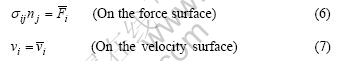
where ��ij is the stress component, ![]() and vi are strain rate and velocity component respectively,
and vi are strain rate and velocity component respectively, ![]() is the flow stress that is the function of the stress, strain rate and temperature,
is the flow stress that is the function of the stress, strain rate and temperature, ![]() is the effective strain rate,
is the effective strain rate, ![]() is the external force.
is the external force.
The above field equation can be resolved by the following variation principle:
![]()
where V and S are the volume and surface area of the deformable body, respectively, K is a large positive constant for incompressible metal.
3 Friction modelThe constant shear friction is adopted in this paper.
The frictional force in the constant shear model is defined by
f=mk (9)
where f is the frictional stress, k is the shear yield stress and m is the friction factor. Eqn.(9) shows that the friction is a function of the yield stress of the deforming body.
4 Finite element model
Concave bus bar is the key component of the generator. The schematic diagram of concave bus bar section is shown in Fig.1, where A=8 mm, a=5 mm, B=28 mm, b=16 mm, R1=1 mm, R2=3 mm, R3=5 mm.
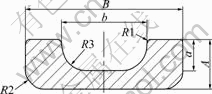
Fig.1 Schematic diagram of concave bus bar section
The commercial software DEFORM-3D is applied to simulate the process. Fig.2 shows the detailed geometry and mesh for the extrusion wheel, the compaction wheel, the shoe, the abutment, the die and the rod.
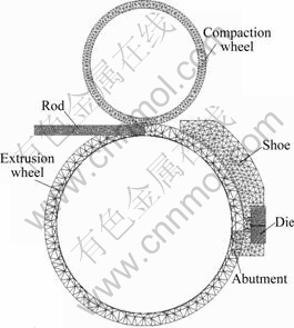
Fig.2 Finite element model
The deforming metal is copper. Its material model can be obtained through the following equation:
![]()
where ![]() is the flow stress,
is the flow stress, ![]() is the effective plastic strain,
is the effective plastic strain, ![]() is the effective strain rate and TK is the temperature.
is the effective strain rate and TK is the temperature.
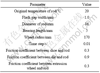
The relationship between flow stress and strain for pure alloy at temperatures of 20, 200, 400, 500, 600 and 800 �� is shown in Figs.3(a) and (b) when the effective strain rate is 2.0 and 3.0 s-1, respectively. The input parameters for the non-isothermal CONFORM process are listed in Table 1.
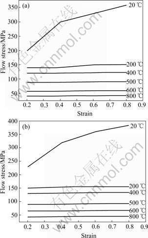
Fig.3 Relationship between flow stress and strain for pure alloy at different temperatures: (a) ![]() =2.0 s-1; (b)
=2.0 s-1; (b) ![]() =3.0 s-1
=3.0 s-1
Table 1 Parameters used for simulation
5 Simulation results and discussion
The extrusion wheel angular velocities are 0.837 6, 1.047 0 and 1.256 4 rad/s, respectively. The detailed distributions of the deformation body temperature field, stress field, strain field, velocity field and damage field of the metal are obtained by simulation.
5.1 Distribution of velocity field
The distribution of deformation body velocity field under different extrusion wheel angular velocities is shown in Fig.4. It shows that the change of metal flow velocity is larger in the adjacent regions of the flash gap than that in the die. With increasing extrusion wheel angular velocity, the metal flow velocity increases in the die orifice gradually. Particularly, the metal flow velocity increases slowly when the extrusion wheel extrusion wheel angular velocity is high. So increasing the extrusion wheel angular velocity will not improve the angular velocity is higher. This proves that the slippage between the rod and extrusion wheel occurs when the productivity if the extrusion wheel angular velocity reaches a given value. At the same time, the dead zone occurs in the front corner of the die. This will make the oxide remain in the extrusion cavity. So the product quality can be improved.
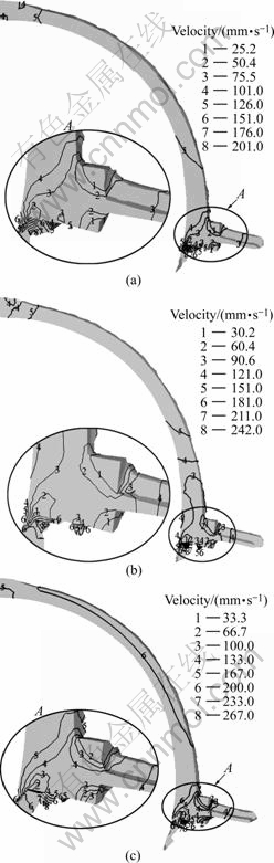
Fig.4 Distribution of velocity field at different extrusion wheel angular velocities: (a) ��=0.837 6 rad/s; (b) ��=1.047 0 rad/s; (c) ��=1.256 4 rad/s
5.2 Distribution of effective stress field
Fig.5 shows the distribution of the deformation body effective stress under different extrusion wheel angular velocities. The effective stress near the die orifice enhances gradually with increasing extrusion wheel angular velocity. High stress is concentrated in adjacent regions of the flash gap. The stress concentration varies with wheel angular velocity. Measurement must be taken to reduce the stress concentration. At the same time, the material of the abutment should have high strength.
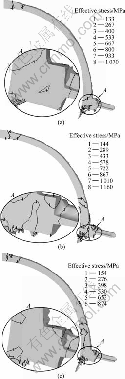
Fig.5 Distribution of effective stress field at different extrusion wheel angular velocities: (a) ��=0.837 6 rad/s; (b) ��=1.047 0 rad/s; (c) ��=1.256 4 rad/s
5.3 Distribution of effective strain field
Fig.6 shows the distribution of the deformation body effective strain under different extrusion wheel angular velocities. The effective strain gradient is larger near the abutment than that near the die orifice. The effective strain of the product increases gradually with increasing extrusion wheel angular velocity. The product quality can be improved by changing the wheel angular velocity. At the same time, the effective strain distribution is uniform in the adjacent regions of the die orifice. So it is feasible to produce concave bus bar by CONFORM technology.
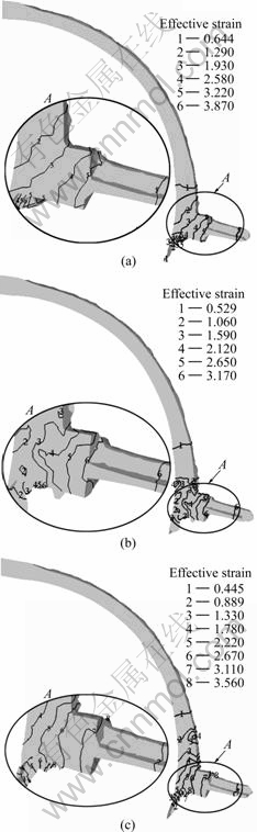
Fig.6 Distribution of effective strain field at different extrusion wheel angular velocities: (a) ��=0.837 6 rad/s; (b) ��=1.047 0 rad/s; (c) ��=1.256 4 rad/s
5.4 Distribution of temperature field
Fig.7 shows the distribution of the deformation body temperature under different extrusion wheel angular velocities. In the deformation process, the deformation body temperature increases remarkably due to friction and deformation. The deformation body tem-perature exceeds 550 �� at the selected extrusion wheel angular velocities. The tools and dies materials cannot work long time when the work temperature surpasses 550 ��. So the cooling is necessary in the region of the die and tools. With increasing extrusion wheel velocity, the deformation body temperature increases gradually.
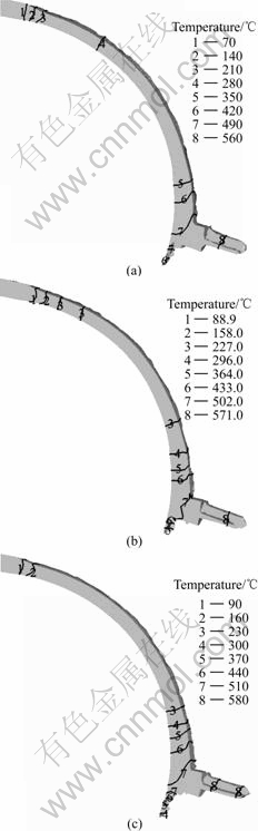
Fig.7 Distribution of temperature field at different extrusion wheel angular velocities: (a) ��=0.837 6 rad/s; (b) ��=1.047 0 rad/s; (c) ��=1.256 4 rad/s
5.5 Distribution of damage field
Damage generally relates to the likelihood of fracture in a part. In general, designing with a damage value from 0.1 to 0.2 will be safe from fracture. Fig.8 shows the detailed damage distribution at different extru- sion wheel angular velocities. It can be seen that the damage value is satisfying under these velocities. At the same time, the damage value decreases with the increase of the extrusion wheel angular velocity.
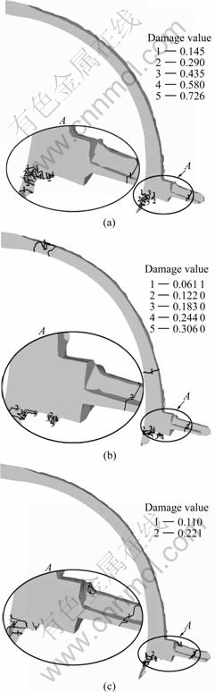
Fig.8 Distribution of damage field at different extrusion wheel angular velocities: (a) ��=0.837 6 rad/s; (b) ��=1.047 0 rad/s; (c) ��=1.256 4 rad/s
6 Conclusions
1) The deformation body flow velocity increases in the die orifice gradually with the enhancement of the extrusion wheel angular velocity. But the slippage between the rod and extrusion wheel occurs when the extrusion wheel angular velocity is high. So increasing the extrusion wheel angular velocity will not improve the productivity if the extrusion wheel angular velocity reaches a given value.
2) The effective stress near the die orifice rises gradually with the increase of the extrusion wheel angular velocity. High stress is concentrated in adjacent regions of the flash gap. Measurement must be taken to reduce the stress concentration. At the same time, the material of the abutment should have high strength.
3) The effective strain gradient is larger near the abutment than that near the die orifice. The effective strain of the product increases gradually with increasing the extrusion wheel angular velocity.
4) In the deformation process, the deformation body temperature increases remarkably due to friction and deformation. So the cooling is necessary in the region of the die and tools. The deformation body temperature increases gradually with increasing the extrusion wheel velocity.
5) The damage value decreases with the increase of the extrusion wheel angular velocity.
References[1] SONG Bao-yun, FAN Zhi-xin, CHEN Ji-guang, LIU Yuan-wen, JIA Chun-bo. Features of copper and aluminum continuous extrusion process and industrial application [J]. Rare Metals, 2004, 28(1): 257-261. (in Chinese)
[2] CHO J R, JEONG H S. Parametric investigation on the curling phenomenon in CONFORM process by three-dimensional finite element analysis [J]. Journal of Materials Processing Technology, 2001(110): 53-60.
[3] CHEN Li. The Three-Dimensional Computer Simulation of Copper Strip Continuous Extrusion Forming Process [D]. Dalian: Dalian Railway Institute, 2004. (in Chinese)
[4] KIM Y H, CHO J R, JEONG H S, KIM K S, YOON S S. A study on optimal design for CONFORM process [J]. Journal of Materials Processing Technology, 1998(80/81): 671-675.
[5] CHU Can-dong, PENG Ying-hong, RUAN Xue-yu. Computer simulation of continuous extrusion forming process [J]. The Chinese Journal of Nonferrous Metals, 2001, 11(S1): 48-51. (in Chinese)
[6] LU J, SALUJA N, RIVIERE A, ZHOU Y. Computer modeling of the continuous forming extrusion process of AA6061 alloy [J]. Journal of Materials Processing Technology, 1998(79): 200-212.
[7] ZHONG Yi. The Continuous Extrusion Forming Technology and its Applications [M]. Beijing: Metallurgical Industry Press, 2004. (in Chinese)
[8] NIU Yu-ying, CHEN Li, SONG Bao-yun. Simulation on continuous extrusion forming process of copper stripe [J]. Nonferrous Metals, 2006, 58(2): 29-33.
[9] HE Sheng-li, ZHANG Chong-gao, WANG Xin-wei, XIE Bin. Principle of conform continuous extrusion and influencing factor on extrusion of copper line [J]. Tool Engineering, 2005, 39(3): 27-30. (in Chinese)
[10] CHEN Li, SONG Bao-yun, YUN Xin-bing. Numerical simulation for conform process of copper strip in chamber [J]. Nonferrous Metals (Refining), 2004(1): 38-40, 43. (in Chinese)
[11] CHU Can-dong, ZHAI Fu-bao, PENG Ying-hong, RUAN Xue-yu. Study on the influence of the wheel angular velocity on the continuous extrusion forming process [J]. Mechanical Science and Technology, 2001, 20(4): 556-557, 570. (in Chinese)
[12] DING Zhi-yong. The Study on Thixoforming Behavior and Model of Semi-Solid Aluminum Alloy [D]. Beijing: General Research Institute for Nonferrous Metals, 2002. (in Chinese)
[13] PENG Ying-hong, RUAN Xue-yu, ZUO Tie-yong. The rigid-viscoplastic finite element analysis of the heat couple conform process [J]. The Chinese Journal of Nonferrous Metals, 1994, 4(3): 60-64. (in Chinese)
[14] PENG Ying-hong. The Numerical Simulation of Conform Deformation Process [D]. Changsha: Central South University of Technology, 1993. (in Chinese)
[15] XIE Ling-ling, SONG Bao-yun. 3D-FEM mathematical simulation of CONFORM extending-forming process for copper bus bar [J]. Forging & Stamping Technology, 2005(3): 72-75. (in Chinese)
Corresponding author: WU Peng-yue; Tel: +86-10-82241161-221; E-mail: wpylover@163.com
Abstract: The continuous extrusion forming process for producing large section copper concave bus bar under different extrusion wheel angular velocities was studied by three-dimensional finite element technology based on software DEFORM-3D. The rigid-viscoplastic constitutive equation was employed in the model. The numerical simulation results show that the deformation body flow velocity in the die orifice increases gradually with the increase of the extrusion wheel angular velocity. But slippage between the rod and extrusion wheel occurs when the extrusion wheel angular velocity is high. The effective stress near the die orifice enhances gradually with increasing extrusion wheel angular velocity. High stress is concentrated in adjacent regions of the flash gap. The effective strain gradient is greater near the abutment than that near the die orifice. The effective strain of the product increases gradually with increasing extrusion wheel angular velocity. In the deformation process, the deformation body temperature increases remarkably due to friction and deformation. So the cooling is necessary in the region of the die and tools.
