
J. Cent. South Univ. (2012) 19: 1098-1108
DOI: 10.1007/s11771-012-1115-1![]()
A plasticity model for sand-structure interfaces
A. Lashkari
Department of Civil & Environmental Engineering, Shiraz University of Technology, Shiraz 71555-313, Iran
? Central South University Press and Springer-Verlag Berlin Heidelberg 2012
Abstract:
The predictive capacity of numerical analyses in geotechnical engineering depends strongly on the efficiency of constitutive models used for modeling of interfaces behavior. Interfaces are considered as thin layers of the soil adjacent to structures boundary whose major role is transferring loads from structures to soil masses. An interface model within the bounding surface plasticity framework and the critical state soil mechanics is presented. To this aim, general formulation of the interface model according to the bounding surface plasticity theory is described first. Similar to granular soils, it has been shown that the mechanical behavior of sand-structure interfaces is highly affected by the interface state that is the combined influences of density and applied normal stress. Therefore, several ingredients of the model are directly related to the interface state. As a result of this feature, the model is enabled to distinguish interfaces in dense state from those in loose state and to provide realistic predictions over wide ranges of density and normal stress values. In evaluation of the model, a reasonable correspondence between the model predictions and the experimental data of various research teams is found.
Key words:
soil-structure interface; sand; dilatancy; bounding surface plasticity��
1 Introduction
The mechanical behavior of soil-structure interfaces is an influential factor in the load-deformation response and the ultimate bearing capacity of the geotechnical engineering structures such as piles, underground structures, reinforced soils, retaining walls, and offshore gravity structures. In the last half century, numerous experimental techniques such as direct shear test [1-5], shaft interface test [6-7], ring torsion test [8], simple shear test [9-10], and particle image velocimetry (PIV) [11] have been devised to investigate various aspects of the interfaces behavior. On the other hand, in the recent years, some researchers applied advanced numerical approaches such as discrete element method to study the behavior of interfaces [12-13]. These studies have revealed that the mechanical response of sand-structure interfaces is influenced by several factors such as stress path, density, normal pressure, normal stiffness, structure roughness, and grains crushability.
Numerous constitutive models have been suggested for modeling of soil-structure interfaces. CLOUGH and DUNCAN [14] introduced an interface model based on the hyperbolic elasticity. To consider the possibility of failure, BRANDT [15] suggested a rigid-perfect plastic interface model. Advanced constitutive models with more notable simulative capacity have been introduced within the classical elasto-plasticity, bounding surface plasticity, and generalized plasticity frameworks. One of the earliest examples of the first group is the elasto-plastic cap model of GHABOUSSI et al [16]. Considering the experimental observations under constant normal stiffness condition, GHIONNA and MORTARA [3] suggested a non-associated flow rule within an improved Cam-Clay type plastic potential function in their elasto-plastic interface model. de GENNARO and FRANK [17] adopted a Mohr-Coulomb failure criterion and proposed an elasto-plastic model considering the phase transformation and the ultimate state of interfaces. DESAI and MA [18] suggested an elasto-plastic interface model based on the disturbed state concept. In the same path, HU and PU [4] took the disturbed state theory for proper simulation of hardening, softening and dilation of rough interfaces. MORTARA et al [19] introduced an interface model based on the framework of bounding surface plasticity. Recently, LIU et al [20] suggested that the critical state soil mechanics concepts can be applied to interfaces within the framework of generalized plasticity. More recently, LASHKARI [21] proposed another generalized plasticity model for sand-structure interfaces subjected to rotational shear.
DAFALIAS and POPOV [22] and DAFALIAS [23] introduced a versatile plasticity framework, the bounding surface plasticity, which has been successfully applied to constitutive modeling of geomaterials. Since then, the bounding surface plasticity has been extensively developed and used in various problems of the constitutive modeling of granular soils such as state dependency and liquefaction [24-29], strength anisotropy [30-31], partial saturation [32] and particle crushing [33].
In this work, formulation of an interface model within the context of the bounding surface plasticity is presented. New state dependent elements are employed to enhance the model predictive capability over the wide ranges of states. In addition, a novel mechanism is introduced which enables the model for proper prediction of the intense tendency to contraction that occurs immediately after the application of tangential stress. The model calibration is described and then, the predictive capacity of the model is demonstrated compared with the experimental data reported by independent research groups. Having relatively fewer parameters compared to the other existing interface models, it has been shown that the proposed model is capable of providing reasonable predictions over wide ranges of density, normal stress and applied normal stiffness condition using a unique set of model parameters.
2 Model general formulation
Modeling of soil-structure interfaces is usually regarded as a simple shear problem [4, 10, 17-21]. By using this interpretation, stress state within the interface zone can be represented by the following vector:
![]() (1)
(1)
where![]() and �� are, respectively, the compressive normal and tangential components of the stress vector with respect to the interface plane. The relative displacement vector corresponding to the above stress field is
and �� are, respectively, the compressive normal and tangential components of the stress vector with respect to the interface plane. The relative displacement vector corresponding to the above stress field is
![]() (2)
(2)
where v and u are normal and tangential relative displacements, respectively. For the sake of simplicity, it is assumed that strains are uniformly distributed inside the interface zone. Using this assumption and by taking t as the average interface thickness, normal and tangential strains are defined by
![]() (3)
(3)
where ��n and ��t are normal and tangential strains, respectively. Experimental studies have revealed that the interface thickness is about 5-10 times of mean grain diameter [4, 19-21, 34]. Herein, t��5d50 is adopted, in which d50 is the mean grain diameter of the soil.
The strain rate vector is decomposed into elastic and plastic parts as
![]() (4)
(4)
where superscripts e and p stand for the elastic and plastic branches of the strain rate vector, respectively. Dot sign ��![]() �� indicates the rate of the corresponding parameter.
�� indicates the rate of the corresponding parameter.
To relate the rates of stress and elastic strain vectors, the following constitutive law is adopted [17]:
![]() (5)
(5)
where Kn and Kt are, respectively, the normal and tangential elastic moduli. Analogues to granular soils, it is assumed that the elastic moduli are pressure dependent through the following laws:
![]() (6)
(6)
where Kn0 and Kt0 are two material parameters, and patm is a reference pressure which is normally taken as the atmospheric pressure (i.e., patm=101 kPa).
In the elasto-plasticity theory, the plastic strain rate vector is calculated by
![]() ����?R (7)
����?R (7)
where R is a vector which defines the plastic strain rate direction. For a real scalar parameter x, ��x?=x if x>0, and zero otherwise; loading index �� indicates the magnitude of tangential plastic strain rate vector. �� is calculated by
![]() (8)
(8)
where Kp is plastic hardening modulus, and n is the vector normal to the yield function. Using Eqs. (4), (5), (7) and (8), with some ordinary mathematical operations and re-arrangement of terms, we obtain
![]() (9)
(9)
Now, by considering Eqs. (1)-(5), (7) and (9), we can have the following constitutive equation which relates the rate of stress vector to the relative displacement rate vector:
![]() (10)
(10)
Yield function expresses the extent of pure elastic behavior. Selection of a narrow wedge-shape yield function in the following form leads to reasonable predictions in many common practical problems [24-33]:
![]() (11)
(11)
where �� (=��/��n) is stress ratio; ��, back stress ratio, is an evolving kinematic hardening parameter defining the angle that the bisector of the yield function makes with the ��n-axis (see Fig. 1). m in Eq. (11) is a parameter which indicates the yield function opening. Reminding that the domain of pure elasticity in granular soils is restricted to the very low stress levels, selection of m�� 0.01 appears reasonable [24-33]. In addition to the elastic strains, plastic (permanent) strains may also be generated when stress state reaches the yield function and attempts to move beyond its domain. This leads to relocation of the axis of the yield function (evolution of ��). In this situation, the yield direction vector, n, is defined normal to the yield function:
![]() (12)
(12)
where s=1 when ��>��, and s=-1 when ��<�� (see Fig. 1).

Fig. 1 Schematic view of yield, bounding, critical and dilatancy surfaces in ��-��n plane [24-33]
It was stated that direction of plastic strain rate is defined by vector R. Herein, a non-associated flow rule is introduced in the following form:
![]() (13)
(13)
Equation (13) implies that |R��|=1, and it can be observed that Rn plays the role of dilatancy in the model
flow rule (dilatancy =![]()
Now, substitution of Eqs. (12) and (13) into Eq. (10) leads to the following constitutive equation in the matrix form relating the rates of stress and relative displacement vectors:
![]()
![]() (14)
(14)
Detailed definition of Kp and d are introduced in the next section.
3 Model special elements with respect to state dependent behavior of interfaces
When interfaces are in dense state, they demonstrate a peak in shear strength if subjected to loadings under constant normal stress condition. The mentioned peak does not emerge for loose interfaces. Besides, for dense interfaces, one can distinguish a stress ratio at which contraction turns into dilation. The rate of contraction decreases, but never turns into dilation when interface is in loose state. A conjugate behavioral pattern can be observed for normal displacement of interfaces subjected to shear under constant normal stress or constant normal stiffness loadings: dense interfaces initially demonstrate contraction which is followed by dilation in moderate and large tangential displacements, whereas loose interfaces always show contraction. It is also observed that the normal and tangential stresses together with normal displacement approach toward asymptote values and eventually remain unchanged at large tangential displacements [3-5, 10, 17]. Unlike the apparent diversity between the general patterns of behavior, the fundamental aspects of interfaces behavior described above can be explained in a unique framework, if the effect of interface state is effectively taken into account. Based on the experimental evidences, EVGIN and FAKHARIAN [10] and LIU et al [20] suggested that the critical state soil mechanics can be extended to include soil-structure interfaces. In the soil mechanics literature, state parameters are common tools which are used to describe the state of geomaterials, uniquely. A number of state parameters for granular soils have been introduced in the literature. Up-to-date reviews on definitions and capability of state parameters can be found in the works of DAFALIAS and MANZARI [25], LASHKARI [29] and PASTOR et al [35]. According to Refs. [29, 25], the following constitutive laws are used here for the state dependent peak and dilatancy (phase transformation) stress ratios:
![]() (15)
(15)
![]() (16)
(16)
where Mb and Md are, respectively, the peak and dilatancy stress ratios (see Fig. 1) and M, nb and nd are the model parameters. In definitions of Mb and Md, the term ln(��nc/��n) plays the role of a state parameter in which ��nc is the critical normal stress on the critical state line corresponding to the current value of void ratio. Critical state line acts as a reference state in recent state parameters [25, 29, 35]. In this work, location of the critical state line in e-��n plane is represented by the following familiar relationship in the soil mechanics:
![]() (17)
(17)
where ec is the critical void ratio; �� is the slope of critical state line in e-ln��n plane; e0 is the critical void ratio at ��n=101 kPa. For dense interfaces (when the interface state is above the critical state line), ��nc>��n and therefore, Mb>M>Md. This implies that both peak strength and phase transformation are permitted for dense interfaces. In an opposite manner, for interfaces in loose state (when the interface state is below the critical state line), one has ��nc<��n, which leads to Mb<><>d. Hence, interface strength increases with tangential displacement, but peak shear strength does not emerge for loose interfaces. Moreover, in loose interfaces, the volume change behavior never turns into dilation and always remains contractive.
Dilatancy function (see Eqs. (13) and (14)), and plastic hardening modulus (see Eqs. (8) and (14)) are respectively introduced by
![]() (18)
(18)
![]() (19)
(19)
where
![]() (20)
(20)
![]() and
and ![]() are non-evolving bounding and dilatancy back stress-ratios, respectively.
are non-evolving bounding and dilatancy back stress-ratios, respectively. ![]() in Eq. (19) is the initial value of the back stress ratio when the most recent loading starts, and h0 is a model parameter [24-25, 29].
in Eq. (19) is the initial value of the back stress ratio when the most recent loading starts, and h0 is a model parameter [24-25, 29].
There are a number of phenomena in micro structural scale which must be addressed in development of the interface constitutive models. Using PIV technique, DEJONG and WESTGATE [11] observed that thickness of the zone of intense shear in interfaces decreases with the increase of applied normal stress. This is because, the required energy forcing particles to roll on each other (namely, to generate dilation) increases for larger normal stresses. Moreover, at the initial stage of shearing, deformation within the interface zone is homogenous. As shear displacement proceeds, strong localization occurs and the steady state of shearing takes place within the interface zone [10-11, 20]. According to experimental evidences, some researchers like KISHIDA and UESUGI [9], GHIONNA and MORTARA [3], and YOSHIMI and KISHIDA [8] suggested that the yielding of interfaces is originated from two independent, but simultaneous mechanisms: initially homogeneous interfaces deform mainly normal to the interface plane, but subsequently the tangential component of displacement overcomes as a consequence of the so-called strong localizations. To consider the above-mentioned phenomena, A in Eq. (18) is introduced through the following mathematical relationship:
![]() (21)
(21)
where A0 and A1 are model parameters, and A0 is usually larger than A1. When a new loading is started, ![]() As a result,
As a result, ![]() leads to relatively massive contraction. If the loading proceeds,
leads to relatively massive contraction. If the loading proceeds, ![]() gradually increases toward its asymptotic value which is
gradually increases toward its asymptotic value which is ![]() As a result, the ratio
As a result, the ratio ![]() tends gradually toward 1. Eventually, at critical state,
tends gradually toward 1. Eventually, at critical state, ![]() and one has A=A1.
and one has A=A1.
4 Model calibration
The presented constitutive model has ten parameters whose calibration methods are described here. Kt0 and Kn0 are related to the elastic branch of behavior. One can construct tangent lines to the very beginning parts of ��-��t curves and estimate Kt0 using Eq. (6). In a similar manner, Kn0 can be determined by data of loading-unloading- reloading curves of pure compression tests. For a number of tests reaching critical state, one can calculate the ultimate stress ratio, ��/��n, at failure and use the average value as M. One can draw critical void ratios versus corresponding ln(��nc/pa) values at critical state and draw the best line fitted to data. Using the result of constant normal stress tests on interfaces in dense state, one can calculate stress ratio at peak tangential stress. At this time, by considering Eq. (15), nb can be obtained from
 (22)
(22)
Similarly, having data of stress ratio at phase transformation of those interfaces in medium and dense state, nd is calculated by
 (23)
(23)
By ignoring the small contribution of elastic displacements, one can have the following relationship based on Eqs. (11), (18), and (20):
![]() (24)
(24)
At the initial state of shearing, the amount of the above relationship indicates A0. Using Eq. (24) in the same manner, A1 is calculated from v-u curves for moderate-large tangential sliding after peak tangential stress.
Finally, it can be simply shown that the following constitutive equation holds for interfaces subjected to constant normal stress condition:
 (25)
(25)
Now, by considering definition of plastic hardening modulus, we have
 (26)
(26)
5 Model evaluation
The stiffness, K, in the direction normal to the interface plane is defined through the following relationship:
![]() (27)
(27)
Two commonly used stiffness boundary conditions in experimental studies are [5,10]
1) K=0, i.e., ![]() (constant normal stress condition)
(constant normal stress condition)
2) K=constant, i.e., ![]() (constant normal stiffness condition)
(constant normal stiffness condition)
In the following sub-sections, the model predictive capacity over wide ranges of normal stress, density, and stiffness boundary condition is evaluated. To this aim, the model predictions are directly compared with the results of interface tests reported by four independent research teams. The physical properties of interfaces and the model parameters used in simulations are respectively given in Tables 1 and 2.
5.1 Model performance over wide range of normal stresses
Using modified direct shear apparatus, HU and PU [4] conducted experiments on dense (ID (=index of relative density)=90%) Yongdinghe sand-steel interfaces under wide range of normal stress values. Predicted behaviors of four interfaces subjected to tangential stress under constant values of ��n=50, 100, 200 and 400 kPa are illustrated together with the experimental data in Fig. 2. A reasonable correspondence is observed between the experimental results and the model simulations.
5.2 Model performance over wide range of densities and normal stresses
SHAHROUR and REZAIE [36] studied the mechanical behavior of Hostun sand-steel interfaces subjected to constant normal stress loading in modified direct shear box. For six interfaces in very loose (ID= 15%) and dense (ID=90%) states, the model simulations are depicted against the measured data in Fig. 3 for ��n=100, 200 and 300 kPa. In each case, it is observed that the model is capable of providing reasonable simulations. While a peak is observed in tangential stress of dense interfaces which is followed by a gentle softening, the response of the initially loose samples is always of hardening type. Moreover, behavior of loose samples is contractive, whereas initial contraction is followed by sharp dilation in dense interfaces. t=7 mm is assumed in all simulations.
Table 1 Physical properties of Yongdinghe [4], Hostun [36], Gioia Tauro [5], and Ottawa [10] sands

Table 2 Amounts of model parameters used in simulations shown in Figs. 2-8

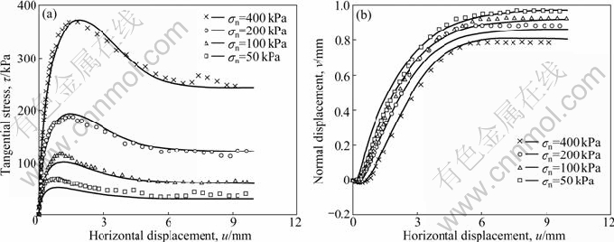
Fig. 2 Comparisons of model predictions with results of four constant normal stress tests on dense Yongdinghe sand-steel interfaces (data taken from Ref. [4]): (a) Tangential stress; (b) Normal displacement
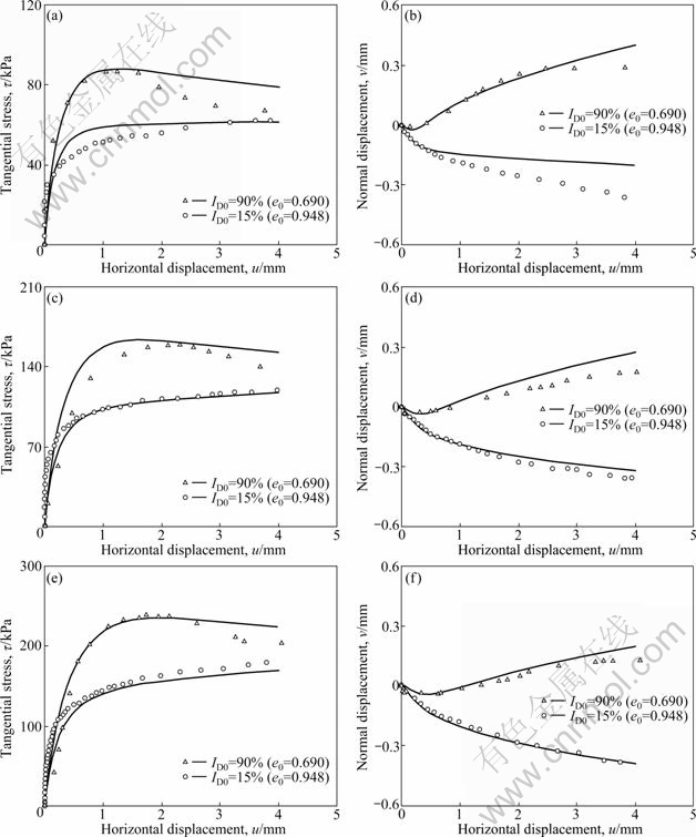
Fig. 3 Comparisons of model predictions with results of six constant normal stress tests on very loose and dense Hostun sand-steel interfaces (data taken from Ref. [36]): (a), (b) ��n=100 kPa; (c), (d) ��n=200 kPa; (e), (f) ��n=300 kPa
As a result of the presence of the state dependent elements in the model formulation, the model can predict the response of sand structure interfaces over wide ranges of density and normal stress values. To study the influence of the state dependent constitutive equations, a number of numerical simulations on variation of these elements are presented here for two tests presented in Figs. 3(e) and (f). Evolution of the peak stress ratio, Mb, with horizontal displacement for the very loose and dense interfaces is studied in Fig. 4(a). It is observed that the values of peak stress ratio for both samples tend toward the critical value of stress ratio, M, at very large horizontal displacements. However, at small and medium horizontal displacements, peak stress ratio is larger than M for the dense sample. For the loose sample, one can find that the peak stress ratio is smaller than M in the small and medium horizontal displacements. Considering Fig. 4(b), an opposite pattern can be distinguished. For the dense sample, the dilatancy stress ratio, Md, is smaller than the critical value, but it is larger than the critical stress ratio for the loose one. Dilatancy stress ratio tends toward the critical value at large horizontal displacements in both loose and dense interfaces. Evolution of the coefficient of dilatancy, A, versus horizontal displacement is presented in Fig. 4(c) for very loose and dense interfaces. In both cases, the difference from the residual value is very small when the horizontal displacement becomes larger than 2 mm. A very different manner for variation of A is observed when it is depicted against the mobilized stress ratio (see Fig. 4(d)). For any selected stress ratio, the value of A for dense interfaces is always larger than that in loose interfaces. It is interesting to note that the general form of the variation of A for the dense sample is similar to the so-called two mechanisms suggestion by MORTARA et al [19].
5.3 Model performance under constant normal stress and constant normal stiffness conditions
MORTARA et al [5] considered the influence of the applied normal stiffness condition on the mechanical behavior of Gioia Tauro sand-steel interfaces in modified direct shear apparatus. In Fig. 5, the model predictions are illustrated together with the data of three constant normal stress tests (K=0) on medium-dense interfaces (ID=60%). Without changing the model parameters, the mechanical response of three other tests performed on the same interfaces under normal stiffness K=1.0 GPa/m are simulated and shown against the data in Fig. 6. The model is considered successful in simulation of behaviors under both constant normal stress and constant normal stiffness conditions.
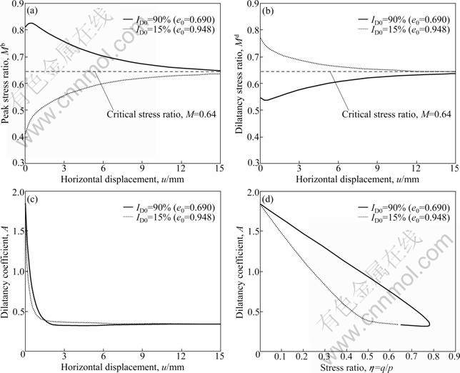
Fig. 4 Evolution of state dependent elements of model for very loose and dense interfaces: (a) Peak stress ratio versus horizontal displacement; (b) Dilatancy stress ratio versus horizontal displacement; (c) Dilatancy coefficient versus horizontal displacement; (d) Dilatancy coefficient versus stress ratio
5.4 Model performance under various stiffness conditions
EVGIN and FAKHARIAN [10] used modified simple shear apparatus to study the mechanical behavior of Ottawa sand-steel interfaces under various stiffness boundary conditions. In all tests, the initial relative density of samples was 88%. For three constant normal stress tests, the model is calibrated and its predictions are compared with experiments in Fig. 7. Without changing the model parameters, comparisons of the model predictions with experiments of three constant normal stiffness tests under K=0.8 GPa/m are illustrated in Fig. 8. For six constant normal stiffness tests conducted under K=0, 0.2, 0.4, 0.6, 0.8 and 1.2 GPa/m, the model predictions are depicted together with the experimental data in Fig. 9. Finally, the stress paths of three tests with K=0.4, 0.8 and 1.2 GPa/m are depicted against experimental data in Fig. 10. In all cases, the model simulations appear realistic compared with the measured behaviors.
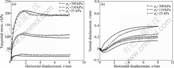
Fig. 5 Model predictions versus results of three constant normal stress tests on medium-dense Gioia Tauro sand-steel interfaces (data taken from Ref. [5]): (a) Tangential stress; (b) Normal displacement

Fig. 6 Model predictions versus results of three constant normal stiffness tests (K=1 GPa/m) on medium-dense Gioia Tauro sand-steel interfaces (data taken from Ref. [5]): (a) Tangential stress versus horizontal displacement curves; (b) Stress paths; (c) Normal displacements versus horizontal displacement curves; (d) Void ratio versus normal stress curves
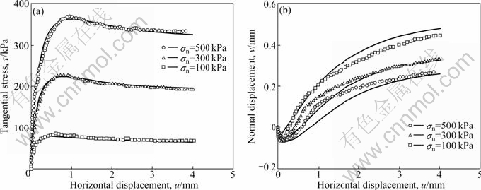
Fig. 7 Model predictions compared with results of three constant normal stress tests on dense Ottawa sand-steel interfaces (data taken from Ref. [10]): (a) Tangential stress; (b) Normal displacement

Fig. 8 Model predictions compared with results of three constant normal stiffness (K=0.8 GPa/m) tests on dense Ottawa sand-steel interfaces (data taken from Ref. [10]): (a) Tangential stress versus horizontal displacement; (b) Tangential stress versus normal stress; (c) Normal stress versus horizontal displacement; (d) Normal displacement versus horizontal displacement

Fig. 9 Model predictions compared with results of six constant normal stiffness (K=0-1.20 GPa/m) tests on dense Ottawa sand-steel interfaces (data taken from Ref. [10]): (a) Tangential stress; (b) Normal stress; (c) Normal displacement
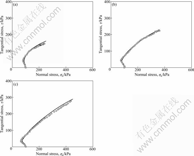
Fig. 10 Predicted stress paths versus measured results of three constant stiffness (K=0.4, 0.8 and 1.2 GPa/m) tests on dense Ottawa sand-steel interfaces (data taken from Ref. [10]): (a) K= 0.4 GPa/m; (b) K=0.8 GPa/m; (c) K=1.2 GPa/m
6 Conclusions
A new constitutive model has been presented for sand-structure interfaces within the frameworks of bounding surface plasticity and critical state soil mechanics. According to the experimental evidences, the mechanical behavior of sand-structure interfaces is affected by numerous factors, among which the effects of density, normal stress, and normal stiffness boundary condition are much paramount. To consider the combined effect of density and applied normal stress, dilatancy and plastic hardening modulus of the model are defined as direct functions of interface state. Moreover, an additional mechanism is suggested to consider massive tendency to contraction observed in the early stage of shearing. Having fewer number of parameters compared to the other existing interface models, it has been shown that the model predictions are in good agreement with the experimental data.
References
[1] POTYONDY J G. Skin friction between various soils and construction material [J]. G��otechnique, 1961, 11(4): 331-53.
[2] DESAI C S, DRUMM E C, ZAMAN M M. Cyclic testing and modeling of interfaces [J]. J Geotech Eng ASCE, 1985, 111(6): 793-815.
[3] GHIONNA V N, MORTARA G. An elastoplastic model for sand-structure interface behavior [J]. G��otechnique, 2002, 52(1): 41-50.
[4] HU L, PU J. Testing and modeling of soil-structure interface [J]. ASCE J Geotech Geoenviron Eng, 2004, 130(8): 851-860.
[5] MORTARA G, MANGIOLA A, GHIONNA V N. Cyclic shear stress degradation and post-cyclic behavior from sand-steel interface direct shear tests [J]. Canadian Geotechnical Journal, 2007, 44: 739-752.
[6] BRUMUND W F, LEONARDS G A. Experimental study of static and dynamic friction between sand and typical construction materials [J]. J Test Eval, 1973, 1(2): 162-165.
[7] ZEGHAL M, EDIL T. Soil structure interaction analysis: Modeling the interface [J]. Can Geotech J, 2002, 39: 620-628.
[8] YOSHIMI Y, KISHIDA T. A ring torsion apparatus for evaluating friction between soil and metal surfaces [J]. Geotech Test J, 1981, 4(4): 145-152.
[9] KISHIDA H, UESUGI M. Tests of interfaces between sand and steel in simple shear apparatus [J]. G��otechnique, 1987, 37(1): 45-52.
[10] EVGIN E, FAKHARIAN K. Effect of stress path on the behavior of sand-steel interface [J]. Can Geotech J, 1996, 33: 853-865.
[11] DEJONG J T, WESTGATE Z J. Role of initial state, material properties, and confinement condition on local and global soil structure interface behavior [J]. ASCE Journal of Geotechnical and Geoenvironmental Engineering, 2009, 135(11): 1646-1660.
[12] JENSEN R P, BOSSCHER P J, PLESHA M E, EDIL T B. DEM simulation of granular media-structure interface: Effect of structure roughness and particle shape [J]. Int J Numer Anal Meth Geomech, 1999, 23: 531-547.
[13] WANG J, DOVE J E, GUTIERREZ M S. Determining particulate- solid interphase strength using shear induce anisotropy [J]. Granular Matter, 2007, 9: 231-240.
[14] CLOUGH G W, DUNCAN J M. Finite element analysis of retaining wall behavior [J]. J Soil Mech & Found Div ASCE, 1971, 97(SM12): 1657-1672.
[15] BRANDT J R T. Behavior of soil-concrete interfaces [D]. Canada: University of Alberta, 1985.
[16] GHABOUSSI J, WILSON E L, ISENBERG J. Finite element for rock joints and interfaces [J]. J Soil Mech & Found Div ASCE, 1973, 99(SM10): 833-848.
[17] de GENNARO V, FRANK R. Elasto-plastic analysis of the interface behavior between granular media and structure [J]. Comput Geotech, 2002, 29: 547-572.
[18] DESAI C S, MA Y. Modeling of joints and interfaces using the disturbed state concept [J]. Int J Numer Anal Meth Geomech, 1992, 16: 623-653.
[19] MORTARA G, BOULON M, GHIONNA V N. A 2-D constitutive model for cyclic interface behavior [J]. Int J Numer Anal Meth Geomech, 2002, 26: 1071-1096.
[20] LIU H, SONG E, LING H I. Constitutive modeling of soil-structure interface through the concept of critical state soil mechanics [J]. Mechanics Research Communications, 2006, 33: 515-531.
[21] LASHKARI A. Modeling sand-structure interfaces under rotational shear [J]. Mechanics Research Communications, 2010, 37: 22-37.
[22] DAFALIAS Y F, POPOV E P. A model of nonlinearly hardening materials for complex loadings [J]. Acta Mechanica, 1975, 21: 173-192.
[23] DAFALIAS Y F. Bounding surface plasticity. I: Mathematical foundation and hypoplasticity [J]. ASCE J Engng Mech, 1986, 112(9): 966-987.
[24] MANZARI M T, DAFALIAS Y F. A critical state two surface plasticity model for sands [J]. G��otechnique, 1997, 47(2): 255-272.
[25] DAFALIAS Y F, MANZARI M T. Simple plasticity sand model accounting for fabric change effects [J]. ASCE J Engng Mech, 2004, 130(6): 622-634.
[26] GAJO A, WOOD D M. Severn-Trent sand: A kinematic-hardening constitutive model: The q-p formulation [J]. G��otechnique, 1999, 49(5): 595-614.
[27] GAJO A, WOOD D M. A kinematic hardening constitutive model for sands: A multiaxial formulation [J]. Int J Numer Anal Methods Geomech, 1999, 23: 925-965.
[28] LI X S. A sand model with state dependent dilatancy [J]. G��otechnique, 2002, 52(3): 173-186.
[29] LASHKARI A. On the modeling of the state dependency of granular soils [J]. Computers and Geotechnics, 2009, 36: 1237-1245.
[30] LI X S, DAFALIAS Y F. Constitutive modeling of inherently sand behavior [J]. ASCE J Geotech Geoenviron Eng, 2002, 128(10): 868-880.
[31] DAFALIAS Y F, PAPADIMITRIOU A G, LI X S. Sand plasticity model accounting for inherent fabric anisotropy [J]. ASCE J Engng Mech, 2004, 130(11): 1319-1333.
[32] CHIU C F, NG C W W. A state-dependent elasto-plastic model for saturated and unsaturated soils [J]. G��otechnique, 2003, 53(9): 809-829.
[33] TAIEBAT M, DAFALIAS Y F. SANISAND: Simple anisotropic sand plasticity model [J]. Int J Numer Anal Meth Geomech, 2008, 32(8): 915-948.
[34] YIN Zong-ze, ZHU Hong, XU Guo-hua. A study of deformation in the interface between soil and concrete [J]. Computers and Geotechnics, 1995, 17(1): 75-92.
[35] PASTOR M, MANZANAL D, FERN?NDEZ MERODO J A, MIRA P, BLANC T, DREMPETIC V, PASTOR M J, HADDAD B, S?NCHEZ M. From solids to fluidized soils: Diffuse failure mechanisms in geostructures with applications to fast catastrophic landslides [J]. Granular Matter, 2010, 12(3): 211-228.
[36] SHAHROUR I, REZAIE F. An elastoplastic constitutive relation for the soil-structure interface under cyclic loading [J]. Computers and Geotechnics, 1997, 21: 21-39.
Received date: 2011-06-27; Accepted date: 2011-10-18
Corresponding author: A. Lashkari, Assistant Professor, PhD; Tel/Fax: +98-711-7264102; E-mail: lashkari_ali@hamyar.net, lashkari@sutech.ac.ir
Abstract: The predictive capacity of numerical analyses in geotechnical engineering depends strongly on the efficiency of constitutive models used for modeling of interfaces behavior. Interfaces are considered as thin layers of the soil adjacent to structures boundary whose major role is transferring loads from structures to soil masses. An interface model within the bounding surface plasticity framework and the critical state soil mechanics is presented. To this aim, general formulation of the interface model according to the bounding surface plasticity theory is described first. Similar to granular soils, it has been shown that the mechanical behavior of sand-structure interfaces is highly affected by the interface state that is the combined influences of density and applied normal stress. Therefore, several ingredients of the model are directly related to the interface state. As a result of this feature, the model is enabled to distinguish interfaces in dense state from those in loose state and to provide realistic predictions over wide ranges of density and normal stress values. In evaluation of the model, a reasonable correspondence between the model predictions and the experimental data of various research teams is found.
