
J. Cent. South Univ. (2016) 23: 2419-2428
DOI: 10.1007/s11771-016-3301-z

Aerodynamic performance analysis of trains on slope topography under crosswinds
LIU Tang-hong(���ú�)1, 2, SU Xin-chao(���³�)1, 2, ZHANG Jie(�Ž�)1, 2,
CHEN Zheng-wei(������)1, 2, ZHOU Xi-sai(��ϸ��)1, 2
1. Key Laboratory of Traffic Safety on Track of Ministry of Education (Central South University), Changsha 410075, China;
2. School of Traffic & Transportation Engineering, Central South University, Changsha 410075, China
 Central South University Press and Springer-Verlag Berlin Heidelberg 2016
Abstract:
This work used the computational fluid dynamics method combined with full-scale train tests to analyze the train aerodynamic performance on special slope topography. Results show that with the increment in the slope gradient, the aerodynamic forces and moment increase sharply. Compared with the flat ground condition, the lateral force, lift force, and overturning moment of the train on the first line increase by 153.2%, 53.4% and 124.7%, respectively, under the slope gradient of 20��. However, with the increment of the windward side��s depth, the windbreak effect is improved obviously. When the depth is equal to 10 m, compared with the 0 m, the lateral force, lift force and overturning moment of the train on the first line decrease by 70.9%, 77.0% and 70.6%, respectively. Through analyzing the influence of slope parameters on the aerodynamic performance of the train, the relationships among them are established. All these will provide a basic reference for enhancing train aerodynamic performances under different slope conditions and achieve reasonable train speeds for the operation safety in different wind environments.
Key words:
train; wind; slope topography; aerodynamic performance��
1 Introduction
There are various line environments around the running train, and the surface morphology of each place is different. When a train runs on a specific surface, the complex morphology would make the characteristics of the flow field around the train more turbulent, which directly affects the aerodynamic performance of the train. In particular, a significant change in the flow field around the train and a rapid increase in the aerodynamic force of the train occur at the wind gap between mountains, where is often subjected to strong wind attacks. Such events greatly increase the probability of derailment and rollover of trains [1-2]. Along the Xinjiang railway lines in China, there is also this area which is frequently battered by gales, and the windy weather usually forces the trains to stop. Thereby passengers and goods are delayed. In some cases, the wind will cause serious injuries or death. This situation affects not only the safety and convenience of the passengers�� travel but also the development of the western economy, resulting in adverse social effects. According to the original incomplete statistics, from 1960 to now the total number of wind-related traffic safety incidents along the Xinjiang railway lines is 38 [3]. To reduce the effect of wind on the safe operation of trains, different types of windbreak walls are built along the railways at wind zones according to the different terrain conditions [4]. These walls play a very important role in the stability of the train during the high-wind season. To determine the safe speed limit of a train under different wind conditions, full-scale train tests, wind tunnel experiments and numerical calculations have been performed in the past 20 years [5-6]. In addition, through a series of in-depth studies on wind disasters in recent years, we have found out that different regions present different wind characteristics. For the slope terrain, based on the field tests, we have discovered that the wind direction is nearly downwards along it due to the influence of the surrounding topography. On February 28th, 2007, the Passenger Train 5807 encountered an overturning accident from Urumqi to Aksu, when the train ran on the K42+380 location between Zhenzhuquan and Hongshanqu Stations in the Southern Xinjiang Railway. The main reason for the rollover accident was the wind directly acted on the train. Moreover, the train was running on an approximately 20��slope, causing the aerodynamic forces and moments of the train to sharply increase and ultimately leading to the rollover of the train. The scene of the accident is shown in Fig. 1. Most of studies on the crosswind stability of the trains under wind conditions mainly focus on various dangerous line conditions, such as high embankments and high bridges [7-10], and limited information is available on slope. Even if there is some research on the effects of topography on the train aerodynamic performance, a conventional flat cutting is selected [11]. In fact, some locations with special topography are generally dangerous for train running safety.
Numerical simulation, wind tunnel test and full- scale test are three effective methods to investigate the train aerodynamic performance under wind environments [12-13], but the full-scale test is severely restricted by field conditions [14]. In the present work, aiming at the scene of the rollover accident in Fig. 1, we analyzed the aerodynamic performance of a train on the special slope topography combined with numerical calculations and full-scale tests, in which the gradient �� and the windward side��s depth H were mainly involved as shown in Fig. 2. Limited by the length of this paper, the results of a full-scale test are just used to validate the numerical calculation method, although we have conducted many full-scale tests under different wind conditions, including nine kinds of vehicles and six kinds of windbreak walls since 2009. In the future we will draft some experimental articles on these tests.
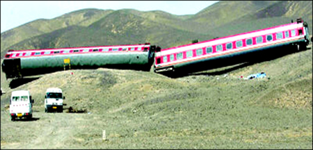
Fig. 1 Scene of rollover accident
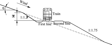
Fig. 2 Road condition on slope topography
2 Investigation of site topography and wind conditions
Windbreak construction along the Southern Xinjiang Railway was finished in 2007. Different types of windbreak walls, including the tendon, embankment and bridge types, were built according to the topography conditions at different zones. Given the effect of topography conditions, the topographical features along the railway that frequently experience special downhill winds are quite different from other lines. Affected by the cold air from Siberia and Ural Mountain, the wind becomes stronger and more frequent. According to existent data, the environmental wind along the railway has the following characteristics: high wind speed, long windy period, strong seasonality and fast wind speed change. Amongst the inland railroads worldwide, the maximum instantaneous wind speed is 64 m/s in this region, together with the highest wind speed and the most severe wind disaster.
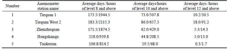
Based on the statistical data of the wind monitoring system from 2004 to 2009 at each anemometer station along the railways, over 100 days per year, the wind level exceeds the Beaufort level 8 (17.2 m/s-20.7 m/s). What��s more, at Tiequan West Station, the number of days reaches up to 183.3 (2155.3 h). By contrast, at Tuokexun anemometer station it is just 106.8 (814.5 h). Specific statistical outputs are listed in Table 1, where the wind speed level is divided according to the Beaufort wind force scale. The statistical basis for high-wind days is that if there is a corresponding level of wind in one day, then it is calculated as one day. The hourly statistics of the gale use a 20-minute interval database; that is, if there is a corresponding level of wind speed within 20 min, it is calculated as 20 min and is then accumulated.
The southern Xinjiang railway is constructed on different slopes of the mountain. Thus, many complex road conditions are formed, such as various cuttings with different depths and slopes, asymmetric cuttings, embankments, and so on. These areas are usually unfavourable to the safe operation of trains. Especially under the downhill wind topography condition, the wind direction is downwards along the slope, and the airflow directly affects the train body, leading to the sharp deterioration in the aerodynamic performance of the train. According to the site investigation, the maximum slope gradient is approximately 20��. Therefore, the 20�� slope was considered the maximum slope gradient in the following analyses.
Table 1 Average annual wind statistics in each anemometer station along southern Xinjiang railway from 2004 to 2009
3 Numerical model
In this work, a single-deck passenger train was used as the research subject. We know that, under a crosswind condition, the number of middle cars has little influence on the performance of the whole train. Thus, shortening the train model does not change the physical characteristics of the flow field around the train. Therefore, we selected four cars as the train models in our study. These four cars consist of a locomotive and three vehicles. The middle car of the three vehicles was analysed for aerodynamic analysis. A resultant wind speed of 60 m/s was given at the inlet as the computational boundary condition, and the Mach number was less than 0.3. So, this was regarded as the incompressible flow problem. The train height h=4.433 m was taken as the reference length under standard atmospheric pressure, the air kinematic viscosity was ��=1.5��10-5 m2/s at the temperature of 20 ��C, and the Reynolds number was Re=Vh/��=1.77��107, which was much larger than the critical Reynolds number for the laminar and turbulent flow. Thus, the flow around the train was turbulent, and the three-dimensional Reynolds- averaged Navier-Stokes equations (RANS) combined with the eddy viscosity hypothesis were used to describe the flow field around the train and behind the windbreak wall.
In the current simulation, the pressure-based solver used the SIMPLEC algorithm to introduce pressure into the continuity equation. A second-order upwind scheme was chosen for solving the Navier�CStokes equations. For the residual of continuity, the absolute criterion of convergence was set to 10-7 with over 6000 iterations. During the calculations, the aerodynamic lateral force and overturning moment are monitored for judging the convergence of the solution.
The calculation zone is shown in Fig. 3. Considering the full development of the wake flow and the lateral flow, the distance from the inlet along the train direction to the train nose was 36.1 h, and the distance from the crosswind inlet to the centre of the railway line was also 36.1 h with a height direction of 22.6 h. The body surface was defined with no-slip wall boundary condition, and the outlet was set to the pressure outlet boundary condition. The bottom walls (track bed, ground, cutting) were defined as the moving walls that were equal and contrary to the train speed. The top of the field was set to the symmetry. The inlet was given the resultant wind speed of 60 m/s, and the aerodynamic performance under other wind speeds and train speeds can be obtained according to the dimensionless coefficient. The environment wind velocity profile is interpolated by the power law, a typical representation for the mean wind profile:
 (1)
(1)
where  is the wind velocity at the height z;
  is the wind velocity at the reference height z0; z is the height from the wind velocity monitor position to the ground; z0 is the reference height (z0=10 m). The parameter �� estimated through the interpolation of the experimental data is equal to 0.12.
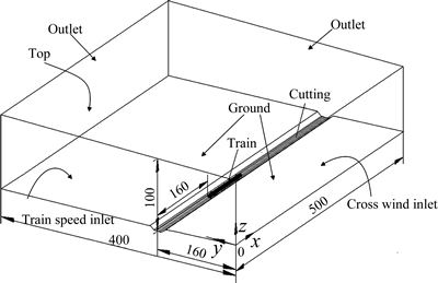
Fig. 3 Calculation zone (Unit: m)
The entire flow field was meshed using unstructured grids, and a local mesh refined method was presented near the body surface, cutting, and lines to improve the accuracy and reliability of the numerical calculation. To determine the effect of mesh resolution on the results, several simulations were conducted at three different meshes with different numbers of cells: coarse, medium and fine meshes consisting of 5.65��106, 6.57��106 and 7.62��106 cells, respectively. In simulations, the wind direction is 15��, 60�� and 90�� with a speed of 60 m/s when the slope gradients are 0��. The overturning moment coefficient is studied as illustrated in Fig. 4. The results of three different meshes closely fit together, which indicates that the coarse mesh is adequate and can be used for the follow-up research. Figure 5 shows the coarse mesh of the train surface.
4 Results and discussion
4.1 Comparison of results between numerical calculation and full-scale test
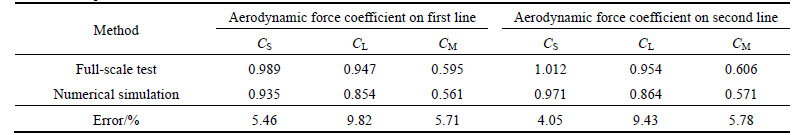
The aerodynamic comprehensive experiments on the trains were performed on the southern Xinjiang railways under windy environments from March to April, 2014. These experiments included static parking tests at different locations and dynamic running tests on the entire line. In the tests, we set up 98 pressure sensors on the surface of the train body and then used partition integral method to obtain the aerodynamic forces and moments. This method is simple but with relatively highaccuracy [15-16]. The measuring points on the full-scale test train are shown in Fig. 6. To obtain the accuracy of the numerical calculation method that was used in this study, we selected the aerodynamic force of the static train on the slope topography which was mainly analysed in the paper for comparison, and the slope gradient was about 14o at the test location. The site of the test train parking at the slope topography is shown in Fig. 7. Figure 7(a) is not very clear, because the experiment was performed in the early morning, and the wind speed exceeded 30 m/s. The comparative data are illustrated in Table 2. The coefficients of the forces and moment are expressed as follows:
Coefficient of the side force:
 (2)
(2)
Coefficient of the lift force:
 (3)
(3)
Coefficient of the overturning moment:
 (4)
(4)
where ��(kg/m3) is the air density; U(m/s) is the wind velocity relative to the train speed; A(m2)(=h��l) is the side area of the car; h(m) is the height of the car and l(m) is the length of the car body.
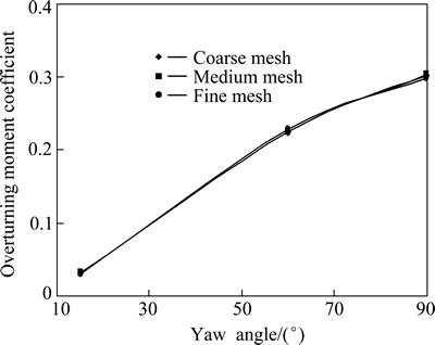
Fig. 4 Overturning moment coefficient of different meshes
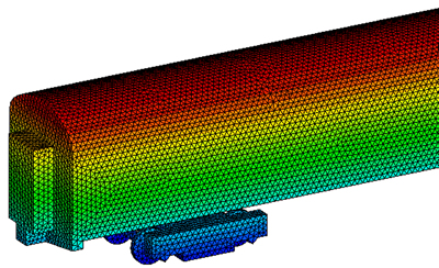
Fig. 5 Mesh of train surface
From Table 2, we can determine that both lateral force and overturning moment coefficients are less than 6%. The lift coefficient has a slightly larger difference between the numerical calculation and full-scale test results (approximately 10%). Both results have good agreement, verifying the credibility of the 3D turbulence model in this work.
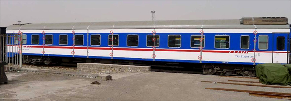
Fig. 6 Measuring point distributions on passenger car in full- scale test
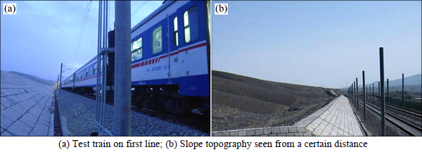
Fig. 7 Scene of full-scale test:
Table 2 Comparison of results between numerical simulation and full-scale test
4.2 Influence of slope gradient on train aerodynamic performance
In the case with the depth of H=3 m, we selected 5 slope gradients [��=0�� (i.e. flat ground), 5��, 10��, 15�� and 20��] to study the train aerodynamic performance in a windy environment and analyse the influence of the slope gradient on train aerodynamics and the flow field around the train. In this analysis, the resultant wind velocity was set to 60 m/s with different yaw angles (15��, 30��, 45��, 60��, 70��, 80�� and 90��), when the train ran on the first line (near the windward side of the line) and on the second line (near the leeward side).
4.2.1 Analysis of train aerodynamic forces
Figures 8 and 9 show the results of the train aerodynamic calculation under different wind yaw angles when the slope gradients are 0��, 5��, 10��, 15�� and 20��. The results show that regardless of the slope, the aerodynamic forces and moments of the train increase as the yaw angle expands. The aerodynamic moments suffer the most when the yaw angle is 90��. Under the same external condition, the aerodynamic forces and moments of the train have slight differences between the first line and the second line. However, the changes in the train aerodynamic forces and moments under different slope gradients are highly significant. The lateral aerodynamic force and overturning moment increase sharply when the slope gradient expands. The change in the aerodynamic lift force is relatively gentle, but there is a larger difference when the topography changes from a flat ground to a 5�� slope. In addition, on the 15�� and 20�� slopes, the train suffers nearly the same aerodynamic lift force. Thus, the effect of slope on the aerodynamic performance of the train is extremely obvious under windy conditions. The aerodynamic forces and overturning moments of the train that is running on the slope are much higher than those of the train running on the flat ground. When the yaw angle is close to 90��, the aerodynamic forces and moments of the train are particularly large, seriously affecting train traffic safety.
Next, we analyse the change in the train aerodynamic performance with the slope gradient when the yaw angle is 90��, which is the most dangerous situation. Seeing Figs. 8 and 9, under the 90�� wind yaw angle, when the topography changes from a flat ground to slopes gradually, the aerodynamic lateral force, lift force, and overturning moment of the train all increasesharply, and the train on the second line grows more than on the first line. As the slope gradient is 20��, compared with the flat ground condition, the lateral force, lift force and overturning moment increase by 153.2%, 53.4% and 124.7% for the train on the first line, respectively, and 192.5%, 90.6% and 165.2% for the train on the second line, respectively. Obviously, in terms of aerodynamic performance and vehicle safety under the 90�� wind yaw angle, the slope topography has a great influence.
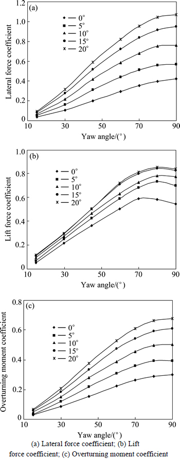
Fig. 8 Aerodynamic performance of trains on first line under different wind yaw angles:
4.2.2 Flow field analysis around train
In this section, the flow field around the vehicle in the case of the 5�� and 20�� slope gradients is analysed. The yaw angle is 90��. The pressure contours around the train on the first and second lines are shown in Fig. 10.
From the pressure contours (Fig. 10), due to the influence of the high speed flow from the left, the windward side of the train body is a positive pressure zone, whereas its top, bottom, and leeward side are all negative pressure zones. As shown in Figs. 10(a) (5�� slope) and 10(c) (20�� slope), in the case of the 20�� slope gradient, the high positive pressure zone of the train body is larger than that of the 5�� slope gradient, and the high positive pressure covers nearly the entire zone from the windward side of the train body to the edge of the slope. However, in the case of the 5�� slope gradient, the high positive pressure zone is much smaller and close to the surface of the train body. Then, it decreases gradually to the low positive pressure on the edge of the slope. Moreover, the negative pressure of the train body on the leeward side of the 20�� slope is greater than that of the 5�� slope. Therefore, the differential pressure between the windward and leeward sides of the train body is larger in the case of the 20�� slope than that of the 5�� slope, and the train body experiences a greater lateral force.
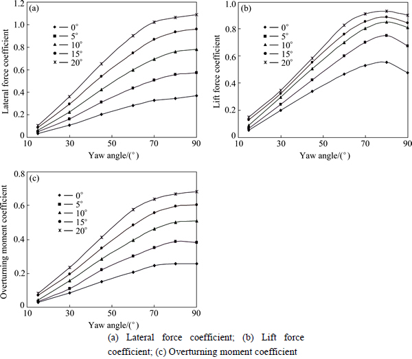
Fig. 9 Aerodynamic performance of trains on second line under different wind yaw angles:
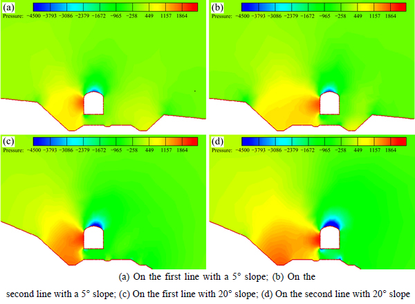
Fig. 10 Pressure contours around train under different slope gradients (Unit: Pa):
The negative pressure area and absolute pressure value at the top of the train body in the case of the 20�� slope are higher than those of the 5�� slope, but the pressure distributions on the train bottom are almost similar. Thus, the differential pressure between the top and bottom of the train body under the 20�� slope is greater than that of the 5�� slope; the lift force is also larger. The overturning moment consists of the lateral and lift forces, in terms of ��force �� lever arm length�� overall components. With the aerodynamic lift and lateral force increasing, the overturning moment of the train increases. Hence, the overturning moment that the train experiences in the case of the 20�� slope is larger than that of the 5�� slope.
Figure 11 shows the velocity vector diagrams around the train on the first line under the environment of the 90�� wind yaw angle in the case of the 5�� and 20�� slope. As shown in the velocity distribution diagrams, the airflow pushs down and accelerates along with the slope direction. The airflow velocity increases sharply over the top of the train body, and under the bottom it is also higher than at both sides of the train body. As shown in Figs. 11(a) (5�� slope) and 11(b) (20�� slope), the bigger slope gradient is, the higher airflow velocity are reached, especially over the top and under the bottom of the train body. This result is corresponded to the aerodynamic force of the train. The streamlines around the train on the first lines in the case of the 5�� and 20�� slope is shown in Fig. 12. It shows that there is no obvious vortex, but the left incoming airflow pushs down and attaches to the direction of the slope topography. The airflow direction is influenced obviously by the slope topography, which strongly influences the distribution of the flow field around the trains. Thus, the aerodynamic performance of train is changed too.
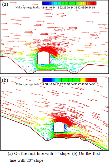
Fig. 11 Velocity vector under different slope gradients (Unit: m/s):
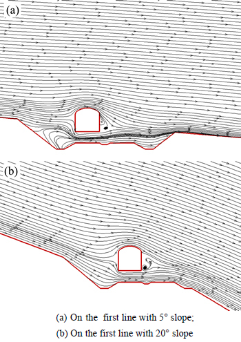
Fig. 12 Streamlines under different slope gradients:
4.3 Influence of windward side��s depth on train aerodynamic performance
In the case of a certain slope gradient (��=10��), different windward side��s depths H (0, 3, 5, 8 and 10 m) were chosen to study the aerodynamic performance of the train on the first and second lines under wind conditions, and analyse the flow field around trains. The depth H was based on the rail level, and the wind velocity was defined as 60 m/s with different yaw angles (15��, 30��, 45��, 60��, 70��, 80�� and 90��).
The influences of different depths on the aerodynamic performances of the train on the first and second lines are shown in Figs. 13 and 14, respectively. According to the results, regardless of the depth, as the yaw angle increases, the train aerodynamic forces also become higher. And the aerodynamic force of the second line is greater than that of the first line. With the depth increasing, the aerodynamic lift, lateral force, andoverturning moment decrease rapidly. Therefore, in the wind environment, the influence of the slope topography on the vehicle aerodynamics not only depends on the slope gradient but also the windward side��s depth. This work will help guide the safe operation of trains and optimise the windbreak facilities along the Xinjiang railways.
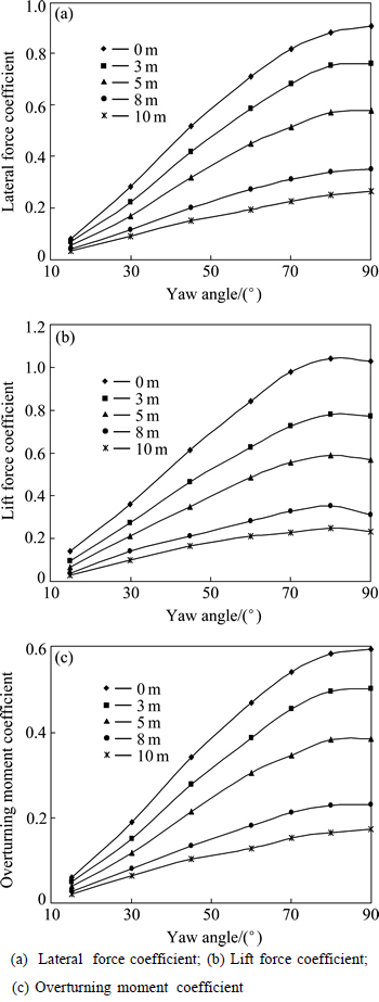
Fig. 13 Aerodynamic performance of train on the first line under different depths and yaw angles:
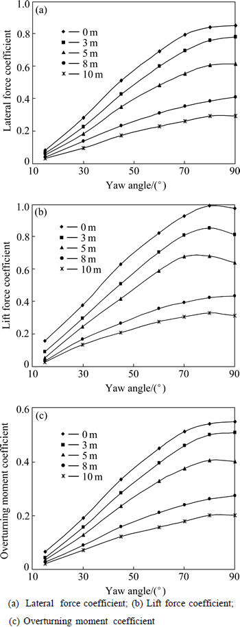
Fig. 14 Aerodynamic performance of train on the second line under different depths and yaw angles:
By analysing the above data and chart, we can also determine that the aerodynamic lateral force, lift force and overturning moment decrease sharply with an increment in the depth. Under the condition of the most adverse wind environment (90�� yaw angle), when the depth is up to 10 m, compared with the 0 m, the lateral force, lift force, and overturning moment of the train on the first line decrease by 70.9%, 77.0% and 70.6%, respectively, and those of the train on the second line decrease by 65.3%, 67.7% and 63.7%, respectively. Evidently, the depth has a large influence on the train aerodynamic performance and operation safety, and the improvement effect of the train on the first line is better than on the second line. Thus, for the slope topography, to set up enough deep is an effective measure to guarantee the safety of the trains under crosswinds.
Because the flow field around the train under different depths is similar to that under different slope gradient, here is no longer a detailed analysis.
4.4 Regression analysis of train aerodynamic performance with slope parameters
This section mainly studies how the overturning moment coefficient and the wind yaw angle are related to the key geometric parameters of the slope, and the larger overturning moment coefficients on the first or second lines are chosen for analysis. Based on the regression analysis of the slope gradient ��, depth H and yaw angle ��, the regression relational expressions are obtained which are the prediction equations for the train overturning moment coefficient under the conditions of the slope and the wind environment.
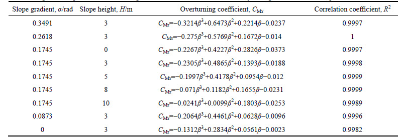
According to the requirements and test procedures for the crosswind assessment [17], in the wind environment, the train aerodynamic overturning moment coefficient has a cube relationship with the wind yaw angle. Therefore, initially, the overturning moment is fitted into the coefficient CM of different slope gradients and slope heights that the train experienced to the cubic polynomial about the wind yaw angle ��, and the corresponding formulas are listed in Table 3, where the radians are used to express the wind yaw angle and slope gradient. From this table, the squares of the correlation coefficient (R2) of the regression relational expressions are evidently all approaching to 1. It means that the relevance between the train overturning moment coefficient and the wind yaw angle is significant on the slope topography. Thus, fitting the overturning moment coefficient CM with the wind yaw angle �� is advisable, through the cubic polynomial.
To further analyze the relationship among the overturning moment coefficient CM, the slope gradient �� and the slope height H, the relationships with the yaw angles are still reserved. In simpler words, a common factor 10-4 is taken. Then, set -�� as the coefficient of ��3, b as the coefficient of ��2, c as the coefficient of ��, and -d as the constant term. The regression equations in Table 3 are expressed uniformly as
 (5)
(5)
The data in Table 3 are then used for the regression analysis. Coefficients a, b, c and d can be expressed through the following regression equations by the slope gradient �� and depth H:
a=-113.05��2-29.73H 2+5184.60��+69.60H+1451.91 (6)
b=-1839.58��2-83.76H 2+10481.09��+355.03H+2708.74 (7)
c=-308.12��2+54.97H 2+5091.84��-619.29H+1831.71 (8)
d=-1602.15��2+7.86H 2+1100.14��-85.58H+211.87 (9)
The squares of correlation coefficient R2 above the regression equations are all more than 0.92, and the four coefficients a, b, c and d are correlated well with the slope gradient �� and slope height H, which shows that the relationship of the train overturning moment coefficient and the key geometrical parameters of the slope and wind yaw angle is reliable by using the above relational expressions.
Table 3 Regression equations of overturning moment coefficients under different yaw angles and different slopes
5 Conclusions
1) The purpose of this work is to analyse the effect of the special slope topography, with different slope gradients and depths, on the train performance. In a special road condition, the aerodynamic forces are the largest when the yaw angle is 90��.
2) With an increment in the slope gradient, the aerodynamic lateral force, lift force, and overturning moment of the train increase sharply as well. When the slope gradient is 20��, compared with the flat ground condition, the lateral force, lift force, and overturning moment for the train on the first line increase by 153.2%, 53.4% and 124.7%, respectively, and by 192.5%, 90.6% and 165.2% on the second line, respectively.
3) The depth of the windward side of a slope has a significant influence on the train aerodynamic performance and operation safety. When the depth reaches 10 m, compared with the 0 m, the lateral force, lift force, and overturning moment of the train on the first line decrease by 70.9%, 77.0% and 70.6%, respectively, whereas those of the train on the second line decrease by 65.3%, 67.7% and 63.7%, respectively.
4) It is indicated that the slope topography is a dangerous road condition for train running safety in a windy environment. The relations between the slope parameters and the train aerodynamic performance are established, which will provide the basis for determining the train aerodynamic performance under different parameters of slopes and the reasonable train speed limit of safe operation in different wind environments.
References
[1] DIEDRICHS B, SIMA M, ORELLANO A, TENGSTRAND H. Crosswind stability of a high-speed train on a high embankment [J]. Proceedings of the Institution of Mechanical Engineers, Part F: Journal of Rail and Rapid Transit, 2007, 221(2): 205-225.
[2] BAKER C, HEMIDA H, IWNICKI S, XIE G, ONGARO D. Integration of crosswind forces into train dynamic modeling [J]. Proceedings of the Institution of Mechanical Engineers, Part F: Journal of Rail and Rapid Transit, 2011, 225(2): 154-164.
[3] GE Sheng-chang, JIANG Fu-qiang. Analyses of the causes for wind disaster in strong wind area along Lanzhou-Xinjiang railway and the effect of windbreak [J]. Journal of Railway Engineering Society, 2009, 26(5): 1-4. (in Chinese)
[4] LIU Feng-hua. Wind-proof effect of different kinds of wind-break walls on the security of trains [J]. Journal of Central South University: Science and Technology, 2006, 31(1): 176-182. (in Chinese)
[5] TIAN Hong-qi. Train aerodynamics [M]. Beijing: Railway Publishing House, 2007: 224-252. (in Chinese)
[6] KRAJNOVIC S, RINGQVIST P, NAKADE K, BASARA B. Large eddy simulation of the flow around a simplified train moving through a crosswind flow [J]. Journal of Wind Engineering and Industrial Aerodynamics, 2012, 110(11): 86-99.
[7] IMAI T, FUJII T, TANEMOTO K, SHIMAMURA T, MAEDA T, ISHIDA H, HIBINO Y. New train regulation method based on wind direction and velocity of natural wind against strong winds [J]. Journal of Wind Engineering and Industrial Aerodynamics, 2002, 90(12): 1601-1610.
[8] XIANG Jun, HE Dan, ZENG Qing-yuan. Effect of cross-wind on spatial vibration responses of train and track system [J]. Journal of Central South University of Technology, 2006, 16(3): 520-524.
[9] BETTLE J, HOLLOWAY A G L, VENART J E S. A computational study of the aerodynamic forces acting on a tractor-trailer vehicle on a bridge in cross-wind [J]. Journal of Wind Engineering and Industrial Aerodynamics, 2003, 91(1): 573-592.
[10] ZHANG T, XIA H, GUO W W. Analysis on running safety of train on bridge with wind barriers subjected to cross wind [J]. Wind and Structure, 2013, 17(2): 203-225.
[11] LIU Tang-hong, ZHANG Jie. Effect of landform on aerodynamic performance of high-speed trains in cutting under cross wind [J]. Journal of Central South University, 2013, 20(3): 830-836.
[12] MOHEBBI M, REZVANI M A. Numerical calculations of aerodynamic performance for ATM train at crosswind conditions [J]. Wind and Structure, 2014, 18(5): 529-548.
[13] WANG D L, WANG B J, CHEN A R. Vehicle-induced aerodynamic loads on highway sound barriers Part 2: Numerical and theoretical investigation [J]. Wind and Structure, 2013, 17(5): 479-494.
[14] BAKER C, JONES J, LOPEZ-CALLEJA F, MUNDAY J. Measurements of the cross wind forces on trains [J]. Journal of Wind Engineering and Industrial Aerodynamics, 2004, 92(7): 547-563.
[15] XIONG Xiao-hui, LIANG Xi-feng, GAO Guang-jun, LIU Tang-hong. Train aerodynamic characteristics in strong cross-wind on Lanzhou-Xinjiang railway line [J]. Journal of Central South University: Science and Technology, 2006, 37(6): 1183-1188. (in Chinese)
[16] SANQUER S, BARRE, C, de VIREL M D, CLEON L M. Effect of cross winds on high-speed trains: Development of a new experimental methodology [J]. Journal of Wind Engineering and Industrial Aerodynamics, 2004, 92(7): 535-545.
[17] BS EN 14067-6, Railway applications��Aerodynamics Part 6: Requirements and test procedures for cross wind assessment [S]. London: British Standard Institute, 2010.
(Edited by DENG L��-xiang)
Foundation item: Projects(U1334205, U1134203) supported by the National Natural Science Foundation of China; Project(132014) supported by the Fok Ying Tong Education Foundation, China; Projects(2014T001-A, 2015T002-A, 2015J007-N) supported by China Railways Corporation
Received date: 2015-05-26; Accepted date: 2015-11-15
Corresponding author: LIU Tang-hong, PhD, Associate Professor; Tel: +86-731-82655294; E mail: lthjd@163.com
Abstract: This work used the computational fluid dynamics method combined with full-scale train tests to analyze the train aerodynamic performance on special slope topography. Results show that with the increment in the slope gradient, the aerodynamic forces and moment increase sharply. Compared with the flat ground condition, the lateral force, lift force, and overturning moment of the train on the first line increase by 153.2%, 53.4% and 124.7%, respectively, under the slope gradient of 20��. However, with the increment of the windward side��s depth, the windbreak effect is improved obviously. When the depth is equal to 10 m, compared with the 0 m, the lateral force, lift force and overturning moment of the train on the first line decrease by 70.9%, 77.0% and 70.6%, respectively. Through analyzing the influence of slope parameters on the aerodynamic performance of the train, the relationships among them are established. All these will provide a basic reference for enhancing train aerodynamic performances under different slope conditions and achieve reasonable train speeds for the operation safety in different wind environments.
