
Trans. Nonferrous Met. Soc. China 24(2014) 3265-3273
Accuracy analysis of plane-strain bulge test for determining mechanical properties of thin films
Lin YANG1,2, Shi-guo LONG1,2, Zeng-sheng MA1,2, Zi-han WANG1,2
1. Key Laboratory of Low Dimensional Materials & Application Technology of Ministry of Education, Xiangtan University, Xiangtan 411105, China;
2. School of Materials Science and Engineering, Xiangtan University, Xiangtan 411105, China
Received 8 October 2013; accepted 27 January 2014
Abstract:
The effect of a variety of geometrics, initial conditions and material properties on the deformation behavior of thin films in the plane-strain bulge test was systematically scrutinized by performing the finite element analysis, and then the accuracy of the plane-strain bulge test in determining the mechanical properties of thin films in terms of our finite element results was analyzed. The results indicate that although the determination of the plane-strain modulus in the light of the plane-strain bulge equation is fairly accurate, the calculation of the residual stress is not satisfied as expected, especially for low residual stress. Finally, an approach is proposed for analyzing bulge test data, which will improve the accuracy and reliability of this bulge test technique.
Key words:
thin films; mechanical properties; bulge test; accuracy; finite element analysis;
1 Introduction
Thin films have been widely used in many important applications such as integrated circuits and microelectromechanical systems [1,2]. To improve the reliability, lifespan and stability of thin films and make full use of these materials, an insight into the mechanical properties of thin films is becoming extremely important. Unfortunately, the deformation behavior and dimension of thin film materials are generally different from those of the corresponding bulk materials, hence specialized mechanical testing techniques have had to be developed [3,4]. There are several specialized techniques for measuring the mechanical properties of thin films including nanoindentation tests [5,6], uniaxial tensile tests [7,8], beam bending tests [9,10] and bulge tests [11,12]. Despite the availability of these techniques to measure the mechanical properties of thin films, specimen preparation, the test setup, and even data analysis are still challenges in the field [13].
One of the most promising techniques for characterizing the mechanical behavior of thin films is the bulge test. Since the bulge test was first introduced by BEAMS [14] in 1959, it has been used to measure the mechanical properties of thin films. In this technique, the deflection of a suspended film is measured as a function of applied pressure. By measuring the applied pressure and the resulting deflection, the elastic modulus, residual stress, Poisson ratio and other important parameters such as strength and fracture toughness can be determined by this method [15-18]. Traditionally, the test has suffered from a number of problems related to sample processing and handling ever since it was born; however, with the recent rapid development of Si micromachining technology, these problems are largely solved [3,4,11,19,20]. In general, bulge test experiments can be classified into three categories with respect to the shape of the tested membrane: circular, square, and rectangular. The plane-strain bulge test, which uses a rectangular membrane with aspect ratio larger than 4, results in a state that approximate plane strain is currently the most widely utilized bulge test for freestanding thin film testing, due to its unique advantages [12]: 1) its favorable application of micromachining routes, 2) a more accurate determination of elastic modulus when Poisson ratio is not exactly known and 3) an ideal technique for studying the plastic deformation behavior of thin films. But it should be noted that the plane-strain bulge analytical model was derived by assuming that a long rectangular membrane is in a perfectly plane-strain state. In fact, the resulting stress state in the film is quite complicated [21].
The accuracy and reliability of the bulge test have been analyzed by many researchers. PAN et al [22] verified analytical models of circular and square membrane by finite element analysis. By the same method, SMALL and NIX [23] systematically analyzed the influence of initial conditions such as residual stress and initial height of circular membrane, and then proposed a new approach to improve the accuracy of the spherical membrane bulge equations. VLASSAK [12] and HOHLFELDER [24] investigated the influence of bending stiffness on the deflection of a membrane and showed that bending moment can be ignored except for the edge of the membrane. However, these analyses focused on circular and square membrane bulge test rather than the plane-strain bulge test. Meanwhile, most current work emphasized the importance of controlling the experimental uncertainties instead of improving the accuracy of the method of data analysis in the plane-strain bulge test [17,18,25,26]. So, it is necessary to define a method which can analyze bulge test data to obtain more accurate results.
In this study, finite element method simulations are used to define virtual experiments, allowing a comparison between the actual mechanical properties of thin films and the mechanical properties calculated by the bulge analytical model (using the pressure-deflection data from the simulation). This provides a direct approach to verify the accuracy of the bulge equation in terms of our finite element results. The objectives of this research are to systematically investigate the effects of geometrics, initial condition (residual stress) and material properties on the existing bulge test model, and to define a method of data analysis to improve the accuracy of the plane-strain bulge model.
2 Bulge test principle
Approximated solutions using other different approaches for various membrane shapes have been derived by a number of researchers [18]. VLASSAK and NIX [3] derived an equation including the influence of residual stress to model the deformation of linear elastic rectangular membranes following an energy minimization approach originally developed by TIMOSHENKO [27]. In such a case, the deflection, h, at the center of a membrane of dimensions of 2a��2b is a function of the applied pressure, p, the membrane geometry, and various material parameters:
 (1)
(1)
where E is the elastic modulus; �� is the Poisson ratio; t is the thickness of the film; s0 is the residual stress of the film; a and b are the half width and the half length of the membrane, respectively. The dimensionless form of the above function is:
 (2)
(2)
For a linear elastic membrane, this relationship can be approximated by the following expression:
 (3)
(3)
where C1 is a constant that depends on the membrane geometry; C2 is a function of the membrane geometry and the Poisson ratio. Once the aspect ratio, a/b, of a rectangular membrane exceeds 4, the deflection at the center of the membrane is nearly independent of a/b and can be approximated with the exact solution for an infinitely long rectangular membrane [3,4]. In other words, an infinitely long membrane is a good approximation for rectangular membranes with large a/b. As a result, the stress and strain are distributed uniformly across the width of the membrane, except for the outer edge, where the bending moment is significant. The exact solution for an infinitely long rectangular membrane can be obtained in this case, and Eq. (3) is then rewritten as follows:
 (4)
(4)
where M=E/(1-��2) is the plane-strain modulus. From the above equations, we can find that by plotting p/h-h2 curve it will generate a straight line with a slope which relates to M and the intercept that is proportional to the residual stress. Therefore, the thickness and width of the thin film are known, and both the plane-strain modulus and residual stress can be calculated readily by measuring the deflection versus pressure, and fitting the data to Eq. (4).
Nevertheless, it is important to point out that the real deformation of a rectangular membrane is commonly more complex than a hypothetical deformation, and the plane-strain state is only found near the center of the rectangular membrane. Consequently, the bulge equation is often applied to tests far less ideal [21,28]. In the case, the validity of the plane-strain bulge model will be analyzed by the finite element analysis in the rest of this paper.
3 Finite element model
In order to model the deformation behavior of thin films and verify the preceding analytical solutions of the plane-strain bulge test, finite element method simulations are carried out by using the commercial nonlinear finite element code ABAQUS [29]. Because of symmetry, only one quarter of the rectangular membrane is modeled with a finite element model using 9600 3D quadratic shell elements (element S8R5, an 8-node doubly curved thin shell, reduced integration, and using five degrees of freedom per node) with five Simpson integration points through the thickness, in which 1-, 2- and 3-axis of Cartesian coordinates refer to the directions of width, length and thickness, respectively. The edges of the membrane are assumed to be clamped and any rotation of the edges is completely constrained. The symmetry boundary condition along 2-axis requires that the displacement in the direction of the 1-axis and the rotations about the 2-axis and 3-axis are zero (U1=UR2=UR3=0). Similar boundary conditions are formulated along the 1-axis. The mesh used in calculations and boundary conditions of the model are shown in Fig. 1.
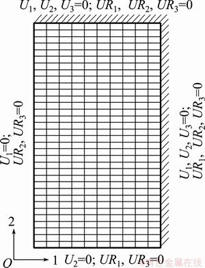
Fig. 1 Schematic illustration of mesh distribution and boundary conditions of finite element model
The FEM models are built by inputting a series of geometric parameters, material parameters and initial conditions (residual stress) into the FEM program and utilize the pressure-deflection output of finite element model to simulate bulge tests. The thin freestanding film is specified as an isotropic elastic material, and the corresponding parameters used for simulations are listed in Table 1. It should be pointed out that no model currently available is suited to wrinkled films caused by compressive residual stress [23], so we will also take no account of this case further. The equal-biaxial tensile residual stress is imposed by manual modification of the input file in the finite element analysis.
Table 1 Parameters used for finite element simulations
4 Results and discussion
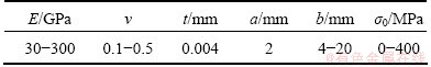
From the preceding section it has become clear that the plane-strain bulge equation was derived by assuming that an infinitely long rectangular membrane under pressure could stay in a perfectly plane-strain state. In fact, the real deformation of a rectangular membrane is much more complex than an assumed deformation. As shown in Fig. 2, the load-deflection output of the plane strain solution is compared with the finite element calculation result. This comparison shows the stiffness of the film to be slightly higher than predicted one. Therefore, the mechanical properties of thin films obtained by applying the existing bulge equation to bulge test data will be somewhat higher than the actual values, and one would not expect that the equation has very high accuracy.
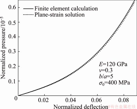
Fig. 2 Pressure-deflection curves calculated using finite element calculation and plane-strain solution for rectangular membrane
In order to analyze and improve the accuracy of the plane strain bulge equation, we systematically scrutinize the effect of geometric sizes, residual stress and material properties on the deformation behavior of thin films by varying the relevant parameters. Moreover, in an attempt to quantify all of these effects on the accuracy of the bulge test equation, we analyze the bulge equation in terms of our finite element results and define a new method of data analysis to improve the accuracy of the plane-strain bulge test.
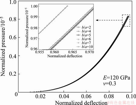
Fig. 3 Pressure-deflection curves obtained from finite element method for various aspect ratios (b/a=2, 4,5,6,7 and 10)
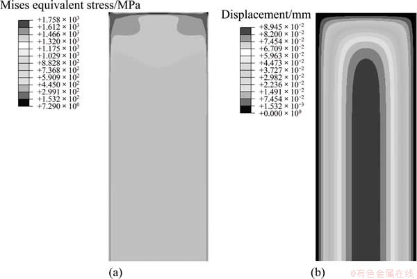
Fig. 4 Contours of von Mises equivalent stress (a) and displacement distribution (b) of rectangular membrane with b/a=5 (The applied pressure is 0.5 MPa)
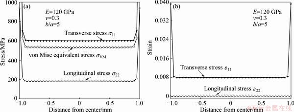
Fig. 5 Finite element model calculations of stress (a) and strain (b) distributions along width of rectangular membrane with b/a=5 (The applied pressure is 0.5 MPa)
4.1 Effect of aspect ratio on accuracy of plane-strain bulge equation
By using the finite element model, the deflection at center of a rectangular membrane is calculated as a function of applied pressure, membrane geometric size and materials parameters. Pressure-deflection curves obtained from the finite element method for various aspect ratios are shown in Fig. 3, and it is confirmed that once the aspect ratio of a rectangular membrane is equal to 5, the deflection of a rectangular membrane is nearly independent of the aspect ratio(b/a) and the membrane is almost in a state of plane strain. Accordingly, the following analysis will be established on this fact that the deflection at center of the membrane with b/a=5 can be approximated with the exact solution for an infinitely long rectangular membrane. Figure 4 shows the contour of the von Mises equivalent stress and displacement obtained from the finite element simulation. Stress and strain distributions in the rectangular film are shown in Fig. 5. As expected, both stress and strain are distributed uniformly across the width of the membrane except for the edge, where high local curvatures induce significant bending moments in the film. It can also be seen that the transverse and longitudinal components of stress and strain are almost constant, while the strain (��22) in the longitudinal direction is nearly zero. So, it is also proved that the membrane is indeed in a state that closely approximates plane strain.
4.2 Effects of elastic constants on deformation behavior of thin films
The constants E and v are varied independently to investigate the effect. It is found that both elastic modulus and Poisson ratio have effect on the deformation behavior of thin films. Figure 6 shows that the deformation of films becomes difficult with increasing elastic modulus and Poisson ratio, and it is obvious that elastic constants have a large effect on the measured pressure-deflection curve. Figure 7 shows the deflection distribution in the film at an applied pressure of 1 MPa. From Fig. 7 we can observe that although the deflection decreases rapidly as the elastic modulus and the Poisson ratio increase, the elastic modulus seems to influence much on stiffening the film deformation behavior compared with the Poisson ratio.
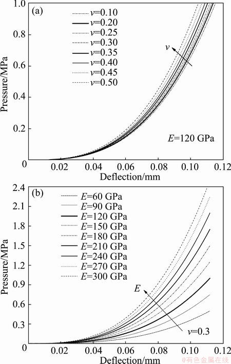
Fig. 6 Pressure-deflection curves generated by finite element model for films of varying Poisson ratio with fixed elastic modulus (a) and of varying elastic modulus with fixed Poisson ratio (b)
4.3 Effects of residual stress on deformation behavior of thin films
In practice, residual stress is inevitably introduced into thin films on substrates and its presence may influence the film deformation behavior. If residual stress is neglected, erroneous material data may be obtained in bulge tests. Like the elastic constants, residual stress also alters the behavior of thin films to some extent. As demonstrated in Fig. 8, with the increase of residual stress, the deflection at the center of the film decreases. Apparently, it is concluded that residual stress can improve the ability to resist the deformation of films.
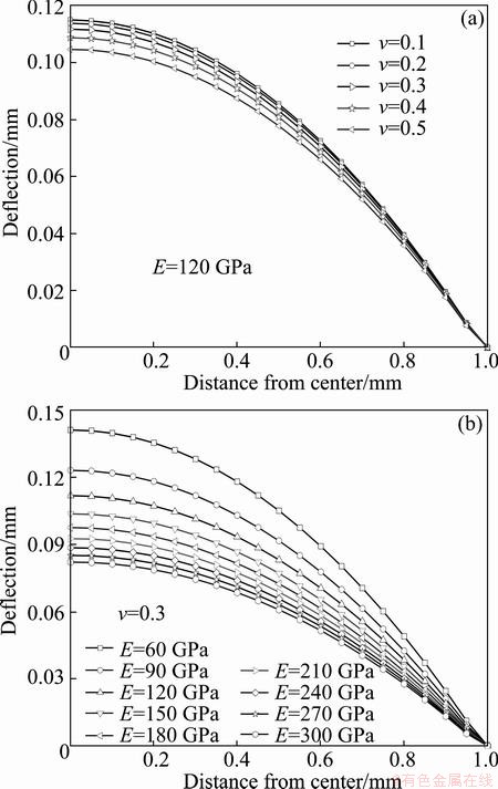
Fig. 7 Deflection distributions along width of film obtained from finite element model for films of varying Poisson ratio with fixed elastic modulus (a) and of varying elastic modulus with fixed Poisson ratio (b) (The applied pressure is 1 MPa)
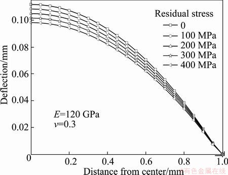
Fig. 8 Deflection distributions along width of rectangular film for various residual stresses (The applied pressure is 1 MPa)
Figure 9(a) shows a plot of pressure-deflection ��data�� extracted from the finite element simulation for various levels of tensile residual stress. And the corresponding p/h-h2 curve is shown in Fig. 9(b), where the slope and the intercept should be proportional to the plane strain modulus and the residual stress, respectively. As expected, the slopes of all the curves are almost the same and the intercepts are evenly spaced.
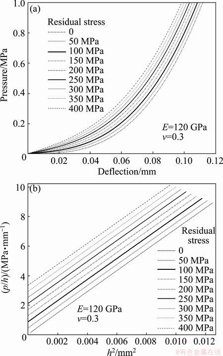
Fig. 9 Pressure-deflection curves for films with different residual stress (a) and corresponding p/h-h2 curves for films with different residual stress (b)
4.4 Effects of elastic constants and residual stress on accuracy of plane-strain bulge equation
Since it is assumed in deriving the plane-strain bulge equation that the film is in a perfect plane-strain state, it is evident that this equation will cause the inconsistency between the measured and actual results. In other words, the determination of materials properties of thin films may be affected by the accuracy of the plane-strain bulge equation, namely the pressure- deflection relation. If the actual materials properties of thin films are known exactly, changes in calculated values of plane-strain modulus and residual stress can be detected according to the existing equation, so that it provides an approach to allow a comparison of the actual materials properties of thin films with the calculated materials properties (using the pressure-deflection data from the simulation). Undoubtedly, it is a feasible method to analyze the accuracy of the plane-strain bulge test model.
In an effort to quantify effects of elastic constants and residual stress on the accuracy of the plane-strain bulge test model, a series of virtual bulge experiments are conducted by making the relevant parameters varied systematically. The subscript ��calc�� refers to the calculated result obtained by inputting the finite element ��data�� to the plane-strain bulge equation Eq. (4), and at the same time the accuracy of the bulge equation is illustrated by comparisons with the calculated and the actual materials properties. As shown in Fig. 10, ratio of the calculated to the actual plane-strain modulus is a function of Poisson ratio and residual stress (Fig. 10(a)) and also a function of elastic modulus and residual stress (Fig. 10(b)). It is found that the ratio of calculated-to- actual plane strain modulus is nearly unity, and slightly greater than one. Both E and v have little effect on the ratio of calculated to actual plane-strain modulus, in addition, increasing s0 makes the calculated modulus decrease, and the error of the calculated modulus is always less than 1.3%. This means that the effect of elastic constants and residual stress on the accuracy of the plane-strain bulge test in determining the plane strain modulus can be ignored, and the existing bulge equation is sufficiently accurate to measure the plane strain modulus.
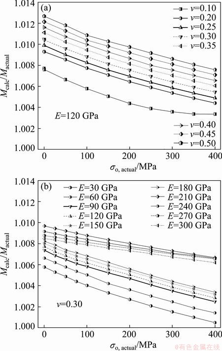
Fig. 10 Ratio of calculated-to-actual plane-strain modulus as a function of residual stress and Poisson ratio (a) and ratio of calculated-to-actual plane-strain modulus as a function of residual stress and elastic modulus (b)
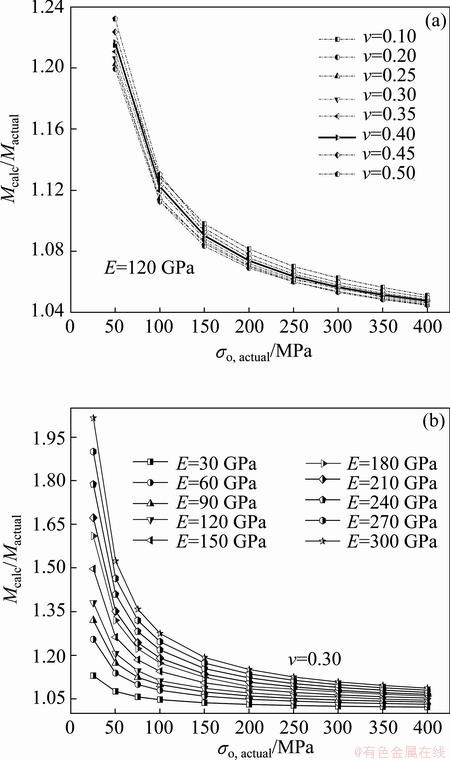
Fig. 11 Ratio of calculated-to-actual residual stress as a function of Poisson ratio and residual stress (a) and ratio of calculated-to-actual residual stress as a function of elastic modulus and residual stress (b)
Being different from the calculated plane strain modulus, the effects of elastic constants and residual stress have a relative large influence on calculated residual stress, as shown in Fig. 11. Furthermore, since the deformation behavior of thin films is dominated by elastic modulus and residual stress rather than Poisson ratio, it is apparent that both of them have a greater impact on the ratio of calculated-to-actual residual stress compared with the influence of Poisson ratio. It can be seen that the ratio of calculated-to-actual residual stress is not a function of Poisson ratio (Fig. 11(a)), and the effect of Poisson ratio on the calculated residual stress is relatively insignificant. Conversely, the variations of elastic modulus and residual stress play a more important role in determining the calculated residual stress (Fig. 11(b)). Note that if the effect of elastic modulus is neglected, especially at lower level of residual stress, erroneous value of the calculated residual stress may be obtained. This may be due to the fact that the low residual stress has some effect on the stiffness. Clearly, it is nearly impossible to obtain accurate results without defining a method which can analyze bulge test data. Thus, an approach that aims to improve the accuracy of the calculated residual stress must be proposed.
Figure 12(a) shows the 3D scatter diagram of the ��data�� in Fig. 11(b). By means of nonlinear surface fitting, an expression for the residual stress as a function of calculated elastic modulus and calculated residual stress can be obtained as follows:
 (5)
(5)
The corresponding fitting surface is shown in Fig. 12(b), and the correlation coefficient of the fitting surface is 0.99912. Subsequently, the values of residual stress corrected by Eq. (5) are plotted in Fig. 13, with the uncorrected curve for E=120 GPa plotted for comparison. The result shows that a quite satisfactory agreement between the corrected value and the actual value of residual stress is obtained. Due to a fact that the variation of calculated residual stress with elastic modulus and residual stress is systematic, and the existing plane bulge equation can provide a more accurate determination of elastic modulus even though Poisson ratio is not known exactly, this formulation should be possible to improve the accuracy of the plane-strain bulge test in determining the residual stress, especially for a lower level of residual stress.
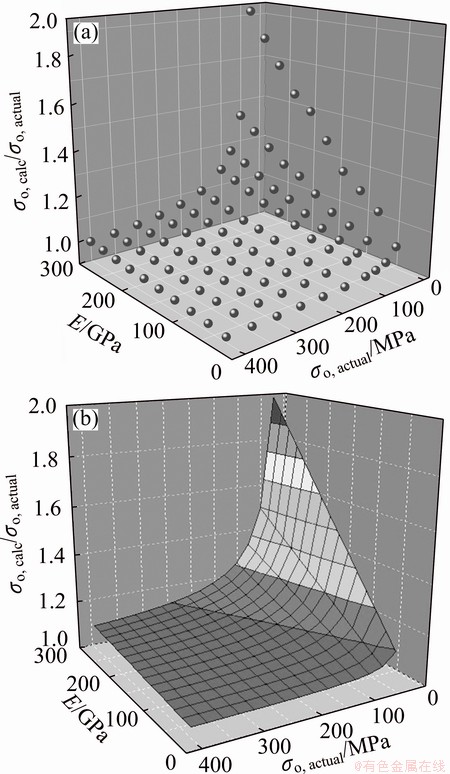
Fig. 12 3D scatter diagram of calculated data obtained from FEA results (a) and corresponding nonlinear fitting surface (b)
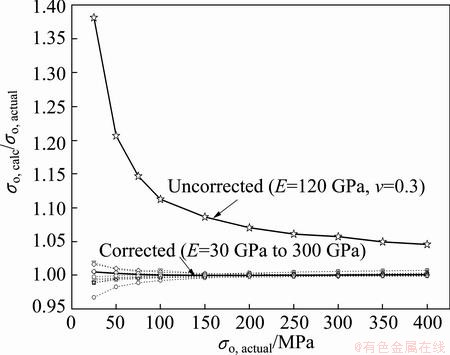
Fig. 13 Values of calculated-to-actual residual stress ratio corrected by using Eq. (5) (An uncorrected curve is plotted for comparison)
5 Conclusions
1) The finite element results show that a long rectangular film will be in a state that closely approximates plane strain as long as the membrane aspect ratio is greater than or equal to 5.
2) Although determination of the plane-strain modulus in the light of the existing plane-strain bulge equation is highly accurate, the calculation of the residual stress is not satisfied as expected, especially for low residual stress.
3) In addition, it is shown that the proposed Eq. (5) for data analysis of the plane-stain bulge test will considerably improve the accuracy of the determination of residual stress.
References
[1] FREUND L B, SURESH S. Thin film materials: Stress, defect formation and surface evolution [M]. Cambridg: Cambridge University Press, 2004: 1-6.
[2] TANG Zhong-bin, XU Fei, LI Yu-long. Determination of mechanical behavior of MEMS materials [J]. Journal of Mechanical Strength, 2007, 29(3): 409-418. (in Chinese)
[3] VLASSAK J J, NIX W D. A new bulge test technique for the determination of Young��s modulus and Poisson��s ratio of thin films [J]. Journal of Materials Research, 1992, 7(12): 3242-3249.
[4] XIANG Y, CHEN X, VLASSAK J J. Plane-strain bulge test for thin films [J]. Journal of Materials Research, 2005, 20(9): 2360-2370.
[5] MA Y, ZHANG Y, YU H F, ZHANG X Y, SHU X F, TANG B. Plastic characterization of metals by combining nanoindentation test and finite element simulation [J]. Transactions of Nonferrous Metals Society of China, 2013, 23(8): 2368-2373.
[6] JIANG L M, ZHOU Y C, HUANG Y L. Elastic-plastic properties of thin film on elastic-plastic substrates characterized by nanoindentation test [J]. Transactions of Nonferrous Metals Society of China, 2010, 20(12): 2345-2349.
[7] HUANG H B, SPAEPEN F. Tensile testing of free-standing Cu, Ag and Al thin films and Ag/Cu multilayers [J]. Acta Materialia, 2000, 48(12): 3261-3269.
[8] PARK J H, KANG D J, SHIN M S, LIM S J, YU S C, LEE K S, HA J E, CHOA S H. Easy calibration method of vision system for in-situ measurement of strain of thin films [J]. Transactions of Nonferrous Metals Society of China, 2009, 19(1): 243-249.
[9] HUANG Xu-lan, BAI Yan-ping, HU Hong-ping, HUANG Hao-sen. Analysis of mechanical properties of microstructure [J]. Journal of Test and Measurement Technology, 2011, 25(4): 308-311. (in Chinese)
[10] MOTZ C, SCHOBERL T, PIPPAN R. Mechanical properties of micro-sized copper bending beams machined by the focused ion beam technique [J]. Acta Materialia, 2005, 53(15): 4269-4279.
[11] JU Xin-hua, REN Feng-zhang, ZHOU Gen-shui, XU Ke-wei, ZHAO Wen-zhen. Inquire into the method of measuring elastic modulus of polymer and metal films in bulge test [J]. Rare Metal Materials and Engineering, 2003, 32(4): 313-316. (in Chinese)
[12] VLASSAK J J. New experimental techniques and analysis methods for the study of the mechanical properties of materials in small volumes [D]. Stanford (USA): Stanford University, 1994: 74-95.
[13] WU C L, YIP M C, FANG W. Improvement of specimen preparation process for bulge test using the combination of XeF2 and deep reactive ion etching [J]. Japanese Journal of Applied Physics-Part 1: Regular Papers and Short Notes, 2009, 48(6): 6FK06.
[14] BEAMS J W. Mechanical properties of thin films of gold and silver [C]//BEAMS J W. Structure and Properties of Thin Films. Nww York: Willey, 1959: 183-192.
[15] KARIMI A, SHOJAEI O R, KRUML T, MARTIN J L. Characterisation of TiN thin films using the bulge test and the nanoindentation technique [J]. Thin Solid Films, 1997, 308: 334-339.
[16] HOHLFELDER R J, LUO H, VLASSAK J J, CHIDSEY C E D, NIX W D. Measuring interfacial fracture toughness with the blister test [C]//GERBERICH W W, GAO H, SUNDGREN J E. Thin Films: Stresses and Mechanical Properties VI, MRS Proceedings. San Francisco: Cambridge Univ Press, 1996: 115-120.
[17] MITCHELL J S, ZORMAN C A, KICHER T, ROY S, MEHREGANY M. Examination of bulge test for determining residual stress, Young's modulus, and Poisson��s ratio of 3C-SiC thin films [J]. Journal of Aerospace Engineering, 2003, 16(2): 46-54.
[18] YOUSSEF H, FERRAND A, CALMON P, PONS P, PLANA R. Methods to improve reliability of bulge test technique to extract mechanical properties of thin films [J]. Microelectronics Reliability, 2010, 50(9): 1888-1893.
[19] BROMLEY E I, RANDALL J N, FLANDERS D C, MOUNTAIN R W. A technique for the determination of stress in thin films [J]. Journal of Vacuum Science & Technology B: Microelectronics and Nanometer Structures, 1983, B1(4): 1364-1366.
[20] SHOJAEI O R, KARIMI A. Comparison of mechanical properties of TiN thin films using nanoindentation and bulge test [J]. Thin Solid Films, 1998, 332(1): 202-208.
[21] NEGGERS J, HOEFNAGELS J P M, HILD F, ROUX S, GEERS M G D. A global digital image correlation enhanced full-field bulge test method [J]. Procedia IUTAM, 2012, 4: 73-81.
[22] PAN J Y, LIN P, MASEEH F, SENTURIA S D. Verification of FEM analysis of load-deflection methods for measuring mechanical properties of thin films [C]//Proceedings of the IEEE Solid-State Sensor and Actuator Workshop, 4th Technical Digest. Hilton Head Island, USA: IEEE, 1990: 70-73.
[23] SMALL M K, NIX W D. Analysis of the accuracy of the bulge test in determining the mechanical properties of thin films [J]. Journal of Materials Research, 1992, 7(6): 1553-1563.
[24] HOHLFELDER R J. Bulge and blister testing of thin films and their interfaces [D]. Stanford (USA): Stanford University, 1999: 54-60. .
[25] JAYARAMAN S, EDWARDS R L, HEMKER K J. Relating mechanical testing and microstructural features of polysilicon thin films [J]. Journal of Materials Research, 1999, 14(3): 688-697.
[26] BESNARD G, HILD F, ROUX S. ��Finite-element�� displacement fields analysis from digital images: Application to Portevin-Le  bands [J]. Experimental Mechanics, 2006, 46(6): 789-803.
[27] TIMOSHENKO S, WOINOWSKY-KRIEGER S. Theory of plates and shells [M]. New York: McGraw-Hill, Inc, 1959: 580.
[28] NEGGERS J, HOEFNAGELS J P M, GEERS M G D. On the validity regime of the bulge equations [J]. Journal of Materials Research, 2012, 27(9): 1245-1250.
[29] ABAQUS 6.5 User's manual [M]. Providence Rhode Island: HKS Inc, 2005.
ƽ��Ӧ��İ�ʵ�������Ĥ��ѧ���ܵľ��ȷ���
�� ��1,2����ʿ��1,2������ʤ1,2��������1,2
1. ��̶��ѧ ��ά���ϼ���Ӧ�ü����������ص�ʵ���ң���̶ 411105��
2. ��̶��ѧ ���Ͽ�ѧ�빤��ѧԺ����̶ 411105
ժ Ҫ����������Ԫ��ϵͳ���о���ƽ��Ӧ��İ�ʵ���йİ��ߴ硢��Ĥ��ʼ�����Լ����ϲ����Ա�Ĥ������Ϊ��Ӱ�졣Ȼ��������Ԫ���������ƽ��Ӧ��İ�ʵ�������Ĥ��ѧ���ܵľ��ȡ��������������ԭ�е�ƽ��Ӧ��İ�����ģ�Ͳ���ƽ��Ӧ��ģ���ľ��Ⱥܸߣ����������������Ӧ���ľ��Ȳ����ߣ��������ڵͲ���Ӧ���Ρ������������������һ���µķ����İ�ʵ�����ݵķ��������ƽ��Ӧ��İ������ľ��ȺͿɿ��ԡ�
�ؼ��ʣ���Ĥ����ѧ���ܣ��İ�ʵ�飻���ȣ�����Ԫ
(Edited by Hua YANG)
Foundation item: Project (11172258) supported by the National Natural Science Foundation of China
Corresponding author: Shi-guo LONG; Tel: +86-731-58228146; E-mail: longsg@xtu.edu.cn
DOI: 10.1016/S1003-6326(14)63466-X
Abstract: The effect of a variety of geometrics, initial conditions and material properties on the deformation behavior of thin films in the plane-strain bulge test was systematically scrutinized by performing the finite element analysis, and then the accuracy of the plane-strain bulge test in determining the mechanical properties of thin films in terms of our finite element results was analyzed. The results indicate that although the determination of the plane-strain modulus in the light of the plane-strain bulge equation is fairly accurate, the calculation of the residual stress is not satisfied as expected, especially for low residual stress. Finally, an approach is proposed for analyzing bulge test data, which will improve the accuracy and reliability of this bulge test technique.
