
J. Cent. South Univ. (2016) 23: 2063-2074
DOI: 10.1007/s11771-016-3262-2

Sliding mode control of solid state transformer using a three-level hysteresis function
LIU Bao-long(������)1, ZHA Ya-bing(���DZ�)1, 2, ZHANG Tao(����)1, 2
1. College of Information System and Management, National University of Defense Technology,Changsha 410073, China;
2. State Key Laboratory of High Performance Computing, National University of Defense Technology,Changsha 410073, China
 Central South University Press and Springer-Verlag Berlin Heidelberg 2016
Abstract:
The solid state transformer (SST) can be viewed as an energy router in energy internet. This work presents sliding mode control (SMC) to improve dynamic state and steady state performance of a three-stage (rectifier stage, isolated stage and inverter stage) SST for energy internet. SMC with three-level hysteresis sliding functions is presented to control the input current of rectifier stage and output voltage of inverter stage to improve the robustness under external disturbance and parametric uncertainties and reduce the switching frequency. A modified feedback linearization technique using isolated stage simplified model is presented to achieve satisfactory regulation of output voltage of the isolated stage. The system is tested for steady state operation, reactive power control, dynamic load change and voltage sag simulations, respectively. The switching model of SST is implemented in Matlab/ Simulink to verify the SST control algorithms.
Key words:
1 Introduction
With distributed energy resources (i.e. distributed generation, storage device) and non-linear loads increasing, the disadvantages of conventional transformer, such as voltage drop under load, sensitivity to harmonics, low performance under DC-offset, need of protection against either short-circuits or overloads or over-voltage, become serious and obvious [1-2]. Therefore, it is very necessary to develop new conversion equipment.
Solid state transformer (SST) is also known as electronic power transformer (EPT) [3], power electronics transformer (PET) [4]. It is proposed as a powerful, highly flexible alternative to conventional transformer. SST can be widely used in the distribution system level, such as voltage transformation and regulation, FACTs functionalities, smart grid integration and fault isolation and limitation [5]. SST can not only realize functions of delivering energy, voltage isolation, but also possesses some merits, such as insensitive to harmonics or user-side faults, voltage sag ride through, fault current limiting, power factor correction, voltage regulation, small volume, light weight, small no-load loss and no need potentially toxic insulated oil [6]. SST has been regarded as one of the ten most emerging technologies in 2011 by MIT technology review and is a one of the key elements in the energy internet [7].
Different topologies have been presented for realizing the SST, in recent years. It is concluded that the three-stage configuration comprising distinct rectifier stage, isolated stage and inverter stage results in the most suitable implementation, especially in energy internet [8-9].
Generally, three-stage SST has three basic control objectives: 1) to keep the sinusoidal input current and in phase with the input voltage to achieve unity input power factor, 2) to maintain the LVDC link voltage at a constant value, 3) to keep the output voltage sinusoidal. In general, PI controllers can be used to meet the requirements of SST design [10-11]. However, the performance of SST with PI controllers, especially designed for specific operation points, has only small signal stability. Several existing advanced control techniques have been considered in the literature such as predictive control [12], nonlinear control [13], optimal control [14]. Although these schemes exhibit good result, it is difficult to provide robust LVDC-link voltage to integrate distributed energy resources, and sensitive to parametric uncertainties. Moreover, three-stage SST is nonlinear in nature, and the performance of SST is strongly affected by external disturbances such as uncertainties of distributed generation, nonlinear load, and source sag/ swell.
Sliding mode control (SMC) is an effective robust tracking control technique, an effective robust tracking control technique, since it offers many distinguished features, including insensitivity to parametric uncertainties, external disturbance rejection and fast dynamic response [15]. SMC is especially suitable for the closed-loop control of SST under load variation and input disturbance [16]. The use of SMC was limited by oscillations caused by sliding effects and limitations on the commutation frequency of power switches. Following advances and performance improvement of electronic power components, the sliding mode control has become more and more effective for electrical systems applications.
Although SST with SMC [17], firstly presented in 2012, provides satisfactory performance, a stable fixed LVDC-link voltage was not considered. In Refs. [10-11], control strategies based on two-level do not take into account the three-level nature of H-bridges in the rectifier stage and inverter stage. A three-level switching function can be used to directly control the switches of rectifier stage and inverter stage. A significant advantage obtained is that a transistor in the rectifier stage and inverter stage is only switched during a half-cycle, while it remains either on or off during the other cycle, resulting in a switching frequency half of what would be used in standard control approaches [18]. Hence, the three-level switching leads to a much lower distortion in the rectifier stage current and inverter stage voltage.
Either dual half bridge (DHB) based or dual active bridge (DAB) based could be used as the isolated stage. Both DHB and DAB provide galvanic isolation and bi-directional power flow [19]. Isolated stage (DHB) with a PI controller has only small signal stability, which is designed around an specific operating point. Considering the nonlinear characteristic of DHB, nonlinear control techniques are likely to result in improvements to the overall the DHB. A nonlinear control approach [20] is utilized to control the DHB. Satisfactory regulation of the output voltage can be ensured by dividing the control task into a real-time linearization stage and linear controller stage. However, the control strategy presented is only suitable for resistive load or consuming load, not for generation load. A modified nonlinear control approach is applied to the DHB for seamless bi-directional power flow control.
In this work, different advanced control methods are applied in three-stage SST. In the rectifier stage, a three-level sliding function is utilized in the current control loop to directly control the switches of rectifier stage, with a switching frequency reduction, while a PI controller is applied in the outer voltage loop, aiming to maintain the output voltage of rectifier stage around its average value. In the isolated stage, a feedback linearization technique using simplified isolated stage model is adopted to improve the large signal stability and achieve good dynamic and steady performances. In the inverter stage, a three-level sliding function is employed in the voltage control loop, which improves the robustness and stability. In order to verify the presented controller scheme for three-stage SST, the switching model of a single phase SST is implemented in Matlab/ Simulink to verify the SST control algorithm.
2 SST model
The SST considered in this paper is a three stage topology consisting of a rectifier stage, an isolated stage, and an inverter stage. A typical actual circuit diagram of SST with three stage topology is depicted in Fig. 1. In the rectifier stage, a single phase H-bridge rectifier is employed to convert the input high voltage AC (HVAC) to HVDC. The isolated stage (DHB) consists of primary side H-bridge, high frequency transformer (HFT), and secondary side H-bridge. The HVDC is fed to the primary side H-bridge and is modulated to a high frequency square wave. Then, the square wave is provided to the HFT and is rectified as LVDC by the secondary side H-bridge. In the inverter stage, a single phase H-bridge inverter is employed to converter LVDC to low voltage AC (LVAC). The mathematical model for each stage is presented in this section.

Fig. 1 Circuit configuration of three-stage SST
2.1 Rectifier stage
The dynamics of rectifier stage for the inner AC current control is described by
 (1)
(1)
and the HVDC link voltage operation:
 (2)
(2)
where 
and
 (3)
(3)
2.2 Isolated stage
DHB also enable seamless bidirectional power flow. As a result, high power density and high efficiency can be achieved. For DHB, the power transferred is given by [21]
 (4)
(4)
where d is the phase shift ratio from the primary side H-bridge to secondary side H-bridge.
It can be shown that the average current flowing out of the secondary side H-bridge(see iDHB2 in Fig. 1) during half of a switching cycle can be given by
 (5)
(5)
Using the average current model it is possible to describe the dynamic behavior of DHB as
 (6)
(6)
2.3 Inverter stage
The behavior of inverter stage for the current and voltage control is described by
 (7)
(7)
 (8)
(8)
where 
and  (9)
(9)
3 Controllers design of SST
Each SST stage (rectifier stage, isolated stage, and inverter stage) has its respective independent controller, which is decoupled from the other stages by means of large intermediate dc-link capacitors (CHVACand CLVAC, as shown in Fig. 1). This section provides a summary of the presented SST controllers.
3.1 rectifier stage
Rectifier stage with SMC is highly robust under parameter uncertainties and external disturbances. A simple but very effective strategy, SMC using a three- level hysteresis switching function, has been presented here to synthesize the internal current control loop of the rectifier stage. The control signals for the rectifier stage switches are obtained directly from a three-level hysteresis switching function. And the external one based on PI controller ensures the control of HVDC link voltage. This scheme ensures sinusoidal input current, power factor correction, constant HVDC link voltage in an average sense. The control block diagram for the rectifier stage is shown in Fig. 2.
Instantaneous reactive power (IRP) P-Q theory [22] is employed in the internal current control loop to achieve independent active power and reactive power control and bi-directional power flow control. In this paper, the second quantity iHVAC_��is obtained by delaying the real one by 1/4 of the line period [23].
The power in IRP theory for single phase is described as
 (10)
(10)
where Precand Qrec are instantaneous active power and reactive power of rectifier stage respectively, iHVAC_��, iHVAC_��, VHVAC_��, VHVAC_�� are the ��-��current and voltage signals. Here, the gain of ��1/2�� in Eq. (10) is because the power in IRP theory for single phase application are one half of what in three phase application. From Eq. (10), the command for the inner current loop could be calculated from the active power and reactive power commands  and
and  shown as

 (11)
(11)

Fig. 2 SST control rectifier stage In fact, in the process of control implementation, the �� term of current reference  is discarded and the �� term of current reference
  is the actual current reference that is applied to the rectifier stage. To simplify,
  is termed as
The sliding surface of internal current control loop for rectifier stage is defined as [24]
 (12)
(12)
It can be easily verified that SMC in Eq. (12) is stable if VHVDC>VHVAC. Since the current reference  is considered constant each commutation period, the time derivative of
  gives
gives
 (13)
(13)
Combining Eq. (3), Equation (13) can also be written as
 (14)
(14)
where  Letting
 then the following existence condition can be satisfied:
  which guaranteees the stability of the reaching mode. The switching law urec=
 should be replaced by a suitable hysteresis function to prevent chattering during sliding mode and in the steady state. In order to enable access to the zero level of the rectifier stage, a three-level hysteresis function such as that shown in Fig. 3(a) is utilized [18]. Two separate two-level function can be utilized to implement the three-level hysteresis to direct drive the switching control signals for the rectifier transistors, as shown is Fig. 3(b).
To maintain the dc output voltage around its average value with desired bandwidth and phase margin, a standard proportional integral (PI) controller is designed as
 (15)
(15)
where
 (16)
(16)

Fig. 3 Three-level hysteresis sliding function (a) and implementation as two-level hysteresis functions (b)
The second harmonic ripple due to the power fluctuation characteristic for a single-phase system is taken into account. A fast moving average (FMA) filter [25] that has a time window with the length corresponding to the period of second harmonic ripple is employed to filtering the measured HVDC-link voltage.
3.2 Isolated stage
Isolated stage with a modified feedback linearization controller is utilized to achieve the satisfactory regulation of the output voltage and seamless bi-directional power flow control. With reference to Eq. (6), a auxiliary input
 is defined as the input to system resulting in:
 (17)
(17)
The controller is designed to satisfy certain damping and bandwidth specifications. The following form is adapted to achieved zero steady-state error as
 (18)
(18)
From Eqs. (17) and (18), the system has the form as

 (19)
(19)
When transformed to the Laplace domain the close-loop transfer function for the system above can be expressed as

 (20)
(20)
where
 (21)
(21)
In Eq. (20), Req_dabis the equivalent output resistance of the isolated stage.
The controller gains are determined by comparing the system of Eq. (21) to the nominal second-order system resulting in
 (22)
(22)
 (23)
(23)
The controller gains can be obtained according to the desired design specifications for the DHB.
The required phase shift d is obtained by solving the definition  :
:
 (24)
(24)
It means that d>0 results in power flow from the primary to the secondary side H-bridge of the DHB and vice versa. The block diagram for the proposed control strategy is presented in Fig. 4. Anti-windup is added to avoid control input saturation during startup and other transient conditions. Note that only the input and output capacitor voltages need measuring.
3.3 Inverter stage
The main task of the inverter stage is to adapt the output voltage to the needs of end-user application, either LVAC load or generation. An SMC using three-level hysteresis Function is used to synthesize the voltage control loop of the inverter stage [18].
Figure 5 shows the complete control scheme for the inverter stage. The output voltage error and its derivative are considered as state variables. The system behavior (referring to Eqs. (7) and (8)) can be obtained as
 (25)
(25)
 (26)
(26)
where  denotes the derivative of x,

 and
and
 (27)
(27)
In Eq. (27), D is considered as a disturbance term. The reference for the output voltage is selected as  The sliding function is defined as
 (28)
(28)
A first order equations  with the solution
  can be used to describe the sliding mode behavior, which is obviously stable if k is positive. And the state variables will move on the sliding surface faster as k increases. To guarantee the stability for the reaching mode, the following existence condition must be assured as
 (29)
(29)
where
 (30)
(30)
Letting then the following stability conditions are obtained as
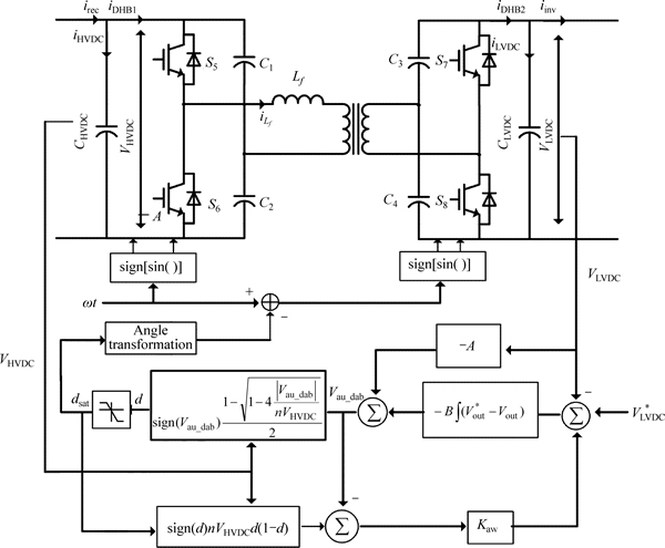
Fig. 4 SST control isolated stage

Fig. 5 SST control inverter stage

 (31)
(31)

 (32)
(32)
Detailed stability analysis can be found in Ref. [18]. The upper bound for the parameter k is provided as
 (33)
(33)
where
 (34)
(34)
In the experimental system, k is chosen to be equal to half of the value in Eq. (33) to guarantee stability in the case of uncertainties in the system.
A three-level hysteresis function shown in Fig. 6(a) is used to replace the switching law uinv=-sign(S(x)), which limit the high switching frequency during the sliding mode and in the steady state.
Note that the derivative of the inverter stage voltage error is involved in the sliding function in Eq. (28). It is well known that the high frequency components in a signal could be amplified in the differentiation operation. In fact, capacitor current feedback was used to avoid the derivative operation in synthesizing the sliding function. Therefore, the state variable x2 can be expressed as  where
where  is the reference for the capacitor current.

Fig. 6 Three-level hysteresis sliding function (a) and implementation as two-level hysteresis functions (b)
4 Simulation results
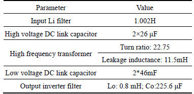
In order to verify the presented controller scheme for three stage SST, a single phase SST prototype is designed as single phase input voltage 50 Hz, 5.8 kV, and DC output 400 V, AC output 50 Hz, 220 V. Table 1 presents the main parameters for SST. The switching model of SST is implemented in Matlab/Simulink to verify the SST control algorithm. The steady stateoperation, reactive power control, dynamic load change and voltage sag simulations are carried out to present the effectiveness of the proposed algorithm over the conventional algorithm.
Table 1 SST main parameters
4.1 Steady state operation of SST to supply both AC and DC port
The steady state operation of SST was carried out to demonstrate the operation of SST as a three-port converter, supplying to both DC and AC low voltage port. As shown in Fig. 7, the input voltage is about 5.8 kV and the load power is about 20 kW, of which the load at the low voltage DC port is about 10 kW (average power) and the load at the voltage AC port is about 10 kW. As can be seen from Fig. 7(a) that the input current is in phase with the voltage, indicating the unity power factor operation. Figure 7(b) shows that the H-bridge voltage of the rectifier stage is almost positive during a half cycle and negative during the other half cycle, achieving three- level operation to result in a good power quality input current. While the sliding mode function of input current is almost in the opposite direction, which is according to the switching law  Figure 7(c) shows the high voltage DC-link is about 9100 V in average sense and the double-line frequency ripple voltage is suppressed below 600 V. Figure 7(d) shows low voltage DC-link voltage is 400 V in average sense and the double-line frequency ripple voltage is suppressed below 4V. Figure 7(e) shows the low voltage AC output voltage 50 Hz, 220 V. Figure 7(f) shows the sliding mode function of the output voltage.
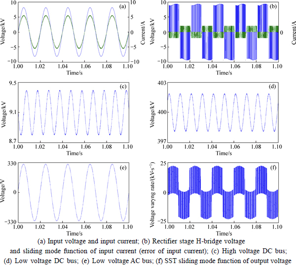
Fig. 7 Simulation results for steady state operation of SST:
4.2 Reactive power compensation of SST
The reactive power regulation capability of SST is also demonstrated in Figs. 8 and 9, in which theproposed algorithm and the conventional algorithm are depicted respectively. The SST transforms the voltages from 5.8 kV to 220 V and the load is about 10 kW at the AC side.

Fig. 8 Simulation results for reactive power compensation of SST (proposed algorithm):

Fig. 9 Simulation results for reactive power compensation of SST (conventional algorithm):
In Figs. 8 and 9, the reactive power at the high voltage is changed from 5 kVar to -5 kVar at 1.2049 s. It is demonstrated from Figs. 8(b) and Fig. 9(b) that the proposed SST control algorithm provides stable and faster reactive power to the grid than the conventional algorithm, therefore can potentially enhance the grid voltage profile.
From Figs. 7(c), Fig. 8(c) and Fig. 9(c), second harmonic ripples in the HVDC-link voltage are observed with different phase positions due to different power factors of rectifier stage.
4.3 Dynamic load change of SST
In order to demonstrate the voltage regulation capability of the designed SST and the proposed control algorithm, the load is changed from 4 kW to 10 kW at 1.2049 s and back to 4 kW at 1.5149 s, as shown in Fig. 11.

Fig. 10 Simulation results for load change operation of SST (proposed algorithm):
Figure 10(a) shows the dynamic response at the rectifier stage, in which the input current also rises due to the increased load condition and drops due to the decreased load condition. Figure 10(b) shows H-bridge voltage of the rectifier stage and the sliding mode function of input current, which gives the stability of the rectifier stage. Figures 10(c) and (d) shows the transient state response of the HVDC-link and LVDC-link voltage. Figure 10(e) shows the dynamic response at the inverter stage, in which the output current also rises as the load increases and drops as the load decreases. Figure 10(f) shows the H-bridge voltage of the inverter stage. Figure 10(g) shows the sliding mode function of the inverter stage rise suddenly due to the load increasing.
Figure 11 shows the sliding function and the state trajectory in the phase plane of inverter stage for this load increasing, which demonstrates the existence of the sliding mode of inverter stage. It can be seen from Fig. 11 that the designed sliding mode controller can drive state trajectory toward the switching line, and the THD is 2.79%. The state trajectory reaches the designed sliding mode and then slides along the switching line with amplitude dependent on the hysteresis band.
Figure 12 shows the simulation result of the conventional algorithm. It can be seen that the conventional algorithm has a higher THD (4.04% in Fig. 12(d)), which indicates that the voltage tracking performance is poor.
4.4 Voltage sag operation of SST
Another distinguished advantage of the proposed SST topology compared with the conventional transformer is the source disturbance rejection capability. Figure 13 shows the 20% voltage sag test of the designed SST prototype and the AC load is 10 kW.
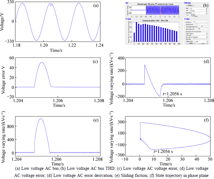
Fig. 11 Simulation results for sliding function and state trajectory in phase plane of inverter stage of SST:

Fig. 12 Simulation results for load change operation of SST (conventional algorithm):
As shown in Fig. 13(a), the voltage sag is created by adjusting the input of rectifier stage and it lasts for 0.4 s. Since the load condition is kept to be the same, the current increases during the voltage sag. Figure 13(b) shows the H-bridge voltage and sliding mode function of input current of rectifier stage, which gives the stability of rectifier stage under source sag condition. Figures 13(c),(d) and (e) show the HVDC-link voltage, LVDC-link voltage and LVAC-link voltage. All the waveforms keep the same during the voltage sag process because of the close-loop regulation and constant load condition. Therefore, the input voltage sag will not affect the power supply quality of the output voltage, indicating a strong source disturbance rejection capability of SST compared with traditional transformer.

Fig. 13 Simulation results for source sag operation of SST:
5 Conclusions
This work presents the advanced controllers design and performance demonstration of a 5.8 kV-220 V/ 20 kVA three-stage solid state transformer for energy internet application. SMC with a three-level hysteresis function is employed in the rectifier stage and the inverter stage. A modified feedback linearization controller is designed in the isolated stage. Several test are conducted and simulation results are given to demonstrate the performance of the designed advanced controllers and the key characters of the designed SST system.
Nomenclature
iHVAC
Input current of rectifier stage
VHVAC
Input voltage of rectifier stage
Li
Input inductor of rectifier stage
VHVDC
Output voltage of rectifier stage
CHVDC
Dc-link capacitor of rectifier stage
iHVDC
Charge current of dc-link capacitor of rectifier stage
irec
Output current of rectifier stage
iDAB1
Input current of isolated stage
Lf
Leakage inductor of high frequency transformer of the isolated stage

Leakage current of high frequency transformer of isolated stage
IDAB1
Output current of isolated stage
ILVDC
Charge current of dc-link capacitor of isolated stage
VLVDC
Output voltage of isolated stage
CLVDC
Dc-link capacitor of isolated stage
Iinv
Input current of inverter stage
Lo
Output inductor of inverter stage

Output inductor current of inverter stage

Charge current of output capacity of inverter stage
ILVAC
Output current of inverter stage
VLVAC
Output voltage of inverter stage
RLoad
Output load of inverter
References
[1] DANNIER A, RIZZO R. An overview of power electronic transformer: Control strategies and topologies [J]. International Symposium on Power Electronics, Electrical Drives, Automation and Motion (SPEEDAM), 2012, 20/21/22: 1552-1557.
[2] RONAN E, SUDHOFF S D, GLOVER S F, GALLOWAY D L. Application of power electronics to the distribution transformer [C]// Conference Record of APEC 2000. New Orleans: APEC, 2000: 861-867.
[3] WANG D, MAO C, LU J, FAN S, PENG F Z. Theory and application of distribution electronic power transformer [J]. Electric Power Syst Res, 2007, 77: 219-226.
[4] ZHU H, LI Y, WANG P, LI Z, CHU Z. Design of power electronic transformer based on modular multilevel converter [C]// Asia-Pacific Power Energy Eng. Conf, Shanghai: APPEEC, 2012: 1-4.
[5] SHE X, BURGOS R, WANG G, WANG F, HUANG A Q. Review of solid state transformer in the distribution system: From components to field application [C]// 2012 IEEE Energy Conversion Congress and Exposition (ECCE). Raleigh, USA: IEEE, 2012: 4077-4084.
[6] HUANG A Q, BALIGA J. FREEDM system: Role of power electronics and power semiconductors in developing an energy internet [C]// Proc of International Symposium on Power Semiconductor Devices, Barcelona: ISPSD, 2009.
[7] SHE X, HUANG,A Q, LUKIC S, BARAN M E. On integration of solid-state transformer with zonal DC microgrid [J]. IEEE Transactions on Smart Grid, 2012, 3(2): 975-985.
[8] HEINEMANN L, MAUTHE G. The universal power electronics based distribution transformer, an unified approach [C]// Power Electronics Specialists Conference, 2001. PESC. 2001 IEEE 32nd Annual. Vancouver Canada: 2001: 504-509.
[9] FALCONES S, MAO Xiao-lin, AYYANAR R. Topology comparison for Solid State Transformer implementation [C]// Power and Energy Society General Meeting. Minneapolis; IEEE, 2010: 1-10.
[10] ZHAO Tie-fu, YANG Li-yu, WANG Jun, HUANG A Q. 270 kVA solid state transformer based on 10 kv sic power devices [C]// Electric Ship Technologies Symposium, 2007. ESTS '07. IEEE, Arlington: IEEE, 2007: 145-149, 21-23.
[11] BHATTACHARYA S, TIEFU Z, GANGYAO W, DUTTA S, SEUNGHUN B, YU D, PARKHIDEH B, ZHOU Xiao-hu, HUANG A Q. Design and development of generation-I silicon based Solid State Transformer [C]// Applied Power Electronics Conference and Exposition (APEC), 2010 Twenty-Fifth Annual IEEE Palm Springs, CA, USA: IEEE, 2010: 1666-1
[12] BRANDO G, DANNIER A, DEL PIZZO A. A simple predictive control technique of power electronic transformers with high dynamic features [C]// PEMD 2010-BRIGHTON, UK: PEMD 2010: 19-21.
[13] LIU H, YANG J, MAO C. Nonlinear control of electronic power transformer for distribution system using feedback linearization [C]// Power Engineering and Automation Conference (PEAM), 2011 IEEE, Wuhan, China: IEEE, 2011: 22-26.
[14] LIU H, MAO C, WANG J L A D. Optimal regulator-based control of electronic power transformer for distribution systems [J]. Electric Power Systems Research, 2009(6): 863-870.
[15] UTKIN V L. Variable structure systems with sliding modes [J]. IEEE Transactions on Automat Contr, 1977, 22(2): 212-222.
[16] JEZERNIK K, ZADRAVEC D. Sliding mode controller for a single phase inverter [C]// Proc IEEE APEC��90, Los Angeles, USA: IEEE, 1990: 185-190.
[17] HOOSHMAND R, ATAEI M, REZAEI M H. Improving the dynamic performance of distribution electronic power transformers using sliding mode control [J]. Journal of Power Electronics, 2012, 12(1): 145-156.
[18] KUKRER O, KOMURCUGIL H, DOGANALP A. A three-level hysteresis function approach to the sliding mode control of single-phase UPS inverters [J]. IEEE Transactions on Ind Electron, 2009, 56: 3477-3486.
[19] ZHAO B, SONG Q, LIU W. Overview of dual-active-bridge isolated bidirectional DC�CDC Converter for high-frequency-link power-conversion system [J]. IEEE Transactions on Power Electronics, 2014, 29(8): 4091-4106.
[20] CARDOZO D D M, BALDA J C, TROWLER D, MANTOOTH H A. Novel nonlinear control of dual active bridge using simplified converter model [C]// Proc IEEE Applied Power Electronics Conf and Exposition. Palm Springs, CA: IEEE, 2010: 321�C327.
[21] ZHAO B, SONG Q, LIU W. Efficiency characterization and optimization of isolated bidirectional dc-dc converter based on dual-phase-shift control for dc distribution application [J]. IEEE Transactions on Power Electron, 2013, 28(14): 1711-1727.
[22] HAQUE M T. Single-phase PQ theory [C]// Power Electronics Specialists Conference. 2002(4): 1815-1820.
[23] ZHANG R, CARDINAL M, SZCZESNY P, DAME M. A grid simulator with control of single-phase power converters in d-q rotating frame [J]. Power Electronics Specialists Conference, 2002, 3: 1431-1436.
[24] NAOUARA M W, BEN HANIAA B, SLAMA-BELKHODJAA I, MONMASSONB E, NAASSANIC A A. FPGA-based sliding mode direct control of single phase PWM boost rectifier [J]. Mathematics and Computers in Simulation, 2013(91): 249-261.
[25] DUJIC D, MESTER A, CHAUDHURI T, COCCIA A, CANALES F, STEINKE J K. Laboratory scale prototype of a power electronic transformer for traction applications [C]// Proc 14th European Conf on Power Electron and Appl, Birmingham: IEEE, 2011: 1-10
(Edited by DENG L��-xiang)
Foundation item: Projects(61403404, 71571187) supported by the National Natural Science Foundation of China
Received date: 2015-04-03; Accepted date: 2015-09-24
Corresponding author: LIU Bao-long, PhD Candidate; Tel: +86-18229981517; E-mail: liubaolong06@126.com
Abstract: The solid state transformer (SST) can be viewed as an energy router in energy internet. This work presents sliding mode control (SMC) to improve dynamic state and steady state performance of a three-stage (rectifier stage, isolated stage and inverter stage) SST for energy internet. SMC with three-level hysteresis sliding functions is presented to control the input current of rectifier stage and output voltage of inverter stage to improve the robustness under external disturbance and parametric uncertainties and reduce the switching frequency. A modified feedback linearization technique using isolated stage simplified model is presented to achieve satisfactory regulation of output voltage of the isolated stage. The system is tested for steady state operation, reactive power control, dynamic load change and voltage sag simulations, respectively. The switching model of SST is implemented in Matlab/ Simulink to verify the SST control algorithms.
