
J. Cent. South Univ. Technol. (2007)06-0803-05
DOI: 10.1007/s11771-007-0153-6
![]()
Optimization of actuator/sensor position of multi-body system with quick startup and brake
TANG Hua-ping(�ƻ�ƽ), TANG Chun-xi(�ƴ�ϲ), YIN Chen-feng(��·�)
(School of Mechanical and Electrical Engineering, Central South University, Changsha 410083, China)
Abstract:
A new method was put forward to optimize the position of actuator/sensor of multi-body system with quick startup and brake. Dynamical equation was established for the system with intelligent structure of piezoelectric actuators. According to the property of the modes varying with time, the performance index function was developed based on the optimal configuration principle of energy maximal dissipation, and the relevant optimal model was obtained. According to its characteristic, a float-encoding genetic algorithm, which is efficient, simple and excellent for solving the global-optimal solution of this problem, was adopted. Taking the plane manipulator as an example, the result of numerical calculation shows that, after the actuator/sensor position being optimized, the vibration amplitude of the multi-body system is reduced by 35% compared with that without optimization.
Key words:
actuator/sensor; multi-body system; active control; optimization; genetic algorithm ��
1 Introduction
In the field of micro-electronics manufacturing, many types of equipment quickly start and stop from one position to another, then to the other position after completing a task. It is very important to decrease the vibration for stable motion of equipment and high manufacturing precision with great startup acceleration and short brake time. It is available to control the vibration from its source for the multi-body system with quick startup and brake. For example, TANG et al[1-2] studied a kind of optimal design method to control load in the vibration of multi-body system with quick startup and brake, which diploid reduce vibration of the system. The vibration of the system can also be controlled by damp according to the basic method of vibration control. Sensors and actuators are finitely used in the vibration control system, so it is necessary to use finite components to perform effective detection and control for dynamics of flexible multi-body system, which is important to optimize the position of actuators and sensors.
Studies on the actuator and sensor allocation are mainly concentrated on two aspects. One is to seek optimal criteria. LONGMAN[3] and LIM[4] proposed the controllable/observable criteria based on control system; CHEN et al[5-6] put forward the criteria based on system energy; MATUNAGA et al[7] proposed the criteria based on controlling system stability and reliability; SUNAR and RAO[8], and KANG et al[9] established the criteria based on system response. The other is to investigate the effective calculated method[10-15] fitting for solving optimal problem.
In the work, according to the characteristic of the model varying with time, the performance index function of the active controlling dissipative total energy was defined based on the optimal configuration principle of energy maximal dissipative, and a float-encoding genetic algorithm, which is quick and reliable to obtain the global-optimal solution of this problem, was adopted.
2 Establishment of model and object function
Based on the theory of FEM and velocity-variation principle, the vibration active control equation of multi-body system with quick start and stop using piezoelectric components as actuator and sensor is built as follows:
![]() (1)
(1)
![]() (2)
(2)
where M, C0, K, Dc and D0 are mass matrix, equivalent damp matrix, equivalent rigidity matrix, control matrix and output matrix, respectively; q is displacement vector; F is generalized force vector of the system, including exogenic forces or exogenic moments applied to the organization besides generated inertia forces of the rigid body movement; uc is an output vector of control. The coefficients are different at different velocities and positions. In this model, the effects of the rigid-elastic coupling, electro-mechanical coupling, actuator and sensor are synthetically considered on the system quality and rigidity, which makes C0 and K in the equations separately asymmetry.
To complete a task in the multi-body system with quick start and stop, at time t0, the rigid body needs to move from position u1(t0) to u1(tf) (u1(t0) is a displacement of rigid body at time t0) in defined time. That is, the velocity of the rigid body equals zero![]() when the rigid body arrives at the position u1(tf)(u1(tf) is a displacement of rigid body at time tf). The vibration control is to get the least vibration of the system by optimizing the driving loads, position of actuators and sensors in the process of start and brake.
when the rigid body arrives at the position u1(tf)(u1(tf) is a displacement of rigid body at time tf). The vibration control is to get the least vibration of the system by optimizing the driving loads, position of actuators and sensors in the process of start and brake.
There are two steps to control vibration.
The first step is to optimize the driving loads. Taking out the second item on the right of Eqn.(1), the new equation is gotten:
![]() (3)
(3)
Then, solving the optimal driving load becomes solving load F, which makes the least vibration in the process of the system moving from position u1(t0) to position u1(tf) in the defined time under load F. So this becomes an optimization problem, i.e. the boundary value problem which satisfies the following differential equation:
 (4)
(4)
![]() (5)
(5)
After solving optimal drive load F, F is substituted into Eqn.(1), then the following equations with given load can be solved:
![]() (6)
(6)
![]() (7)
(7)
The second step is to optimize the position of actuator and sensor.
The aim of optimizing position of actuator and sensor is to make least of vibration the system when the rigid body moves from position u1(t0) to u1(tf) in the defined time. There exists coefficient of the damp matrix in Eqn.(6), which changes with time and is directly proportional to angular velocity of rigid body. There exists coefficient of rigid body matrix that is directly proportional to the square of the angular velocity. For the time is too short for the system with quick start and brake (for example, time is 0.05 s in the wire bonder), the angular velocity is generally small, and the coefficient of rigid body matrix that is directly proportional to the square of the angular velocity is smaller than rigidity coefficient by elastic deformation. Then the rigidity matrix is assumed to be steady; the effect of coefficients on the damp matrix of Eqn.(6) is out of account to optimal analysis of the actuator and the sensor, because the coefficient is directly proportional to the angular velocity of rigid body. And it is a antisymmetric matrix, indicating that it is a kind of gyro force of rigid body movement, and its effect on the elastic vibration of the system is small because its function is only energy conversion and its numeric value is smaller. So the model of the multi-body system with quick start and brake is described as the following form of the state space:
![]() (8)
(8)
where ![]() is the state variable of the generalized coordinates,
is the state variable of the generalized coordinates,
![]()
M��K and C0 are separately the mass matrix, rigidity matrix and damp matrix of the system.
After transforming the state space, the mass matrix, rigidity matrix and damp matrix using the modal coordinates as the state variable separately are as follows:
![]()
![]()
C0=diag [2��i��i],
![]()
![]()
where B(xa) and C(xi) are vibration function matrices that use the positions of the actuator and sensor as variables, and
 ,
,

When the actuator and the sensor have the same disposal, we get
![]()
Adopting the direct velocity output feedback, G is the gain matrix of the feedback, then
![]() (9)
(9)
The relevant state equation of the closed loop system is
![]() (10)
(10)
where
 .
.
For choosing the optimal position of the piezoelectric actuator/sensor from the controlling effect of vibration, the total dissipative energy of the active controller was chosen as the object function[5]. Because the energy of the system reserved is absorbed by two parts that are the structural damp of the system and the active damp of the active control, the maximum dissipative energy of the active controller is equivalent with the minimum total energy of the reserved system, then adopting the following index function:
![]() (11)
(11)
Eqn.(11) is rewritten as
![]() (12)
(12)
where ![]() is the initial point and P is the solution of the following Lyapunov equation:
is the initial point and P is the solution of the following Lyapunov equation:
![]() (13)
(13)
where
![]()
Then, the optimal problem is summarized as a nonlinear optimal problem with constraint.
![]() (14)
(14)
The constraint conditions are![]()
![]()
![]() .
.
3 Genetic operation of float-coded genetic algorithm(FGA)
Independent variables of the optimal problem are regarded as organism in genetic algorithm, and then they are translated into chromosome composed of gene through coding. Relevant value of the object function is defined as fitness and unknown function is defined as environment. The aim of organism is to evolve genotype with optimal fitness.
3.1 Coding
The optimal problem of multi-extrema function is more suitable for the code of decimal floating point data considering precision and calculation on convenience. Every seeking optimal parameter in this work is expressed as a decimal digit, and all the parameters arrayed form an individual.
3.2 Selecting operation
In the genetic algorithm, adaptive value is used to differentiate the individual of colony stand or fall, and the individual with larger adaptive value is better. The genetic algorithm aims at the choice of adaptive value for individual, and assures that the individual with better adaptive value to generate more sub-individual. For disposing convenience, collating choice operation was adopted to hold coincident selection pressure and restrain non-mature convergence preferably. As for the minimum object function, individual is arranged from big to small and uses the serial number as adaptive value after calculating every individual of object function.
3.3 Copying operation
The copying effect is to elevate the average adaptive value. The copying probability of the individual with serial number of rank(x) is
![]() (15)
(15)
where, Pop is the size of the colony, Max��(0, 2), Max+Min=2, rank(x)=1, 2, ��, Pop.
According to the copying probability, roulette mode can be used to do the choice operation. In this work, the following improved mode was adopted. The result of arranged choice is to eliminate m individuals at the back serial number, and the front m individuals are copied twice times respectively and the middle (Pop-2m) individuals are copied once respectively.
3.4 Hybrid operation
Hybrid operation can generate the new individuals, thereby checking and searching the new points in space. The effect of the binary system consistent hybrid operation is to make two relevant parameters a and b become a�� and b��, and satisfy the equation a+b=a��+b��. The hybrid operation on one point is the same, but the consistent hybrid operation is more diverse than the hybrid operation on one point. The hybrid operation of float-coded genetic algorithm(FGA) makes a and b become g1(a, b), g2(a, b). Its aim is to exchange the information of the two individuals. So g1(*) and g2(*) that satisfy Eqn.(16) are considered (the hybrid effect should be assured at the given field):
a+b=g1(a, b)+g2(a, b) (16)
Adopting the following method:
![]() (17)
(17)
where �� and �� are random numbers at interval (0, r). Obviously, this hybrid operation has more results.
3.5 Mutation operation
Considering the mutation operation of the binary system code, its final effect makes an individual parameter c become another value c��. The mutation operation of FGA wants to reach this effect too. Operation can be expressed as
c��=N(c,��) (18)
If c�䣼L, then c��=L; if c�䣾R, then c��=R, where N(c, ��) indicates a random number of normal distribution with equalizing value of c and variance of ��. The parameter is in the range of [L, R]. Obviously, the mutation operation is to mainly do stochastic disturbance in narrow range and to use the centre as the current value. The above mutation operation needs to generate normal distribution and make boundary treatment. It is complex to realize the mutation operation by programming. The following operation is realized easily and has the same effect shown by bulk emulation trial:
![]() (19)
(19)
where 0 and 1 represent two directions of the mutation, c is a random value in the field (0, 1), k��(0,1) is a coefficient, random(2) is a given function to generate random integer of 0 or 1.
3.6 Step of genetic algorithm
For the minimized object function, the procedures of genetic algorithm by floating number coding are as follows.
1) Parameter coding of decimal floating number;
2) Generating the random initial population accord- ing to a certain scale Pop;
3) Calculating the object function value J for each individual;
4) Outputting individual optimal result that satisfy the convergence condition and ending the calculation , or else going on calculating;
5) Proceeding the chosen operation of FGA;
6) Proceeding the cross operation of FGA;
7) Proceeding the mutation operation of FGA;
8) Repeating the third step until a certain perfor- mance index or the defined genetic algebra is satisfied.
4 Optimal algorithmic example
Fig.1 shows a plane manipulator[1]. Object 1 may drive object 2, hinge moment of objects 1 and 2 can make object 2 keep at plane position. The length of the two objects is 0.8 m, cross section is 4 cm2, and the mass of two objects is 2.512 kg. The flexural rigidity of object 1 is 0.275��104 N?m2, and that of object 2 is 1.10��104 N?m2. When object 1 turns from horizontal position to position 30? within 0.2 s, the optimal position of actuator and sensor is analyzed.
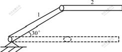
Fig.1 Schematic diagram of plane control instrument
After establishing plane manipulator modal, FGA method was adopted to seek optimum according to the above described steps. The constraint conditions are: 0��xa��0.8, 0��G��50. Choosing population size as 100, m=15, pc=0.8, PM=0.08, the maximal genetic algebra Gmax=100. The optimal values are all found by algorithm in 100 times calculations. The optimal position of actuator and sensor is the position of object 2 near the hinge. Fig.2 shows the upright displacement response of
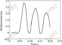
Fig.2 Upright displacement response of right endpoint of object 2 after optimization(actuator and sensor are at the optimal position)
right endpoint of object 2 when actuator and sensor are at the optimal position. Fig.3 shows the upright displacement response of right endpoint of object 2 when actuator and sensor are in the middle of object 2. The displacement of the former is less than that of the latter. The displacement of the former is reduced by 35% compared with that of latter.
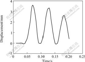
Fig.3 Upright displacement response of right endpoint of object 2 after optimization (actuator and sensor are in the middle of object 2��
5 Conclusions
1) The example shows that the float-coded genetic algorithm and the genetic operation are feasible, quick, efficient.
2) Taking the plane manipulator as an example, the result of numerical calculation shows that, after the actuator/sensor position being optimized, the vibration amplitude of the multi-body system is reduced by 35% compared with that without optimization.
References
[1] TANG Hua-ping, PENG Ya-qing. Optimal design method for force in the vibration control of multi-body system with quick startup and brake[J]. Journal of Central South University of Technology, 2005, 12(4): 335-340.
[2] TANG Hua-ping, TANG Yun-jun, TAO Gong-an. Active vibration control of multibody system with quick startup and brake based on active damping[J]. Journal of Central South University of Technology, 2006, 13(4): 417-421.
[3] LONGMAN R W. Actuator placement from degree of controllability criteria or regular slewing of flexible spacecraft[J]. Acta Astronautic, 1981, 8(7): 703-718.
[4] LIM K B. Method for optimal actuator and sensor placement for large flexible structures[J]. Journal of Guidance Control and Dynamics, 1992, 15(1): 49-52.
[5] CHEN S T, FAN Y H, LEE A C. Effective active damping design for suppression of vibration in flexible system via dislocated sensor/actuator positioning[J]. JSME International Journal: Series C, 1994, 37(2): 252-259.
[6] LEE A C, CHEN S T. Collocated sensor/actuator positioning and feedback design in the control of flexible structure system[J]. Transaction of ASME Journal of Vibration and Acoustics, 1994, 116(4): 146-154.
[7] MATUNAGA S, ONODA J. Actuator placement with failure consideration for static shape control of truss structures[J]. AIAA Journal, 1995, 33(6): 1161-1163.
[8] SUNAR M, RAO S S. Distributed modeling and actuator locations for piezoelectric control system[J]. AIAA Journal, 1996, 34(10): 2200-2203.
[9] KANG Y K, PARK H C, HWANG W. Optimum placement of piezoelectric sensor/actuator for vibration control of laminated beams[J]. AIAA Journal, 1996, 34(9): 1921-1926.
[10] YAN Tian-hong, DUAN Deng-ping, WANG Jian-yu. Collocated sensor/actuator optimal positioning and feedback design by simulated annealing method[J]. Journal of Vibration and Shock, 2000, 19(2): 1-4.
[11] NIU J C, SONG K J. Research on active vibration control based on combined model for coupled systems[J]. Chinese Journal of Mechanical Engineering: English Edition, 2004, 17: 524-527.
[12] NIU Jun-chuan, ZHAO Guo-qun, HU Xia-xia. Active control of structural vibration by piezoelectric stack actuators[J]. Journal of Zhejiang University: Science, 2005, 6A(9): 974-979.
[13] DONG Xing-jian, MENG Guang, PENG Juan-chun. Vibration control of piezoelectric smart structures based on system identification technique: Numerical simulation and experimental study[J]. Journal of Sound and Vibration, 2006, 297(3/5): 680-693.
[14] Simoes R C, Jr Steffen V, HAGOPIAN J D, et al. Modal active vibration control of a rotor using piezoelectric stack actuators[J]. Journal of Vibration and Control, 2007, 13(1): 45-64.
[15] Bongsoo K, MILLS J K. Vibration control of a planar parallel manipulator using piezoelectric actuators[J]. Journal of Intelligent and Robotic Systems: Theory and Applications, 2005, 42(1): 51-70.
Foundation item: Project(50390063) supported by the National Natural Science Foundation of ChinaReceived date: 2007-03-08; Accepted date: 2007-04-27
Corresponding author: TANG Hua-ping, Professor; Tel: +86-731-8830898; E-mail: Huapingt@mail.csu.edu.cn
