

Grain refinement process of pure iron target under hypervelocity impact
NI Chuan-hao, XU Qiang, WANG Fu-chi
School of Materials Science and Engineering, Beijing Institute of Technology, Beijing 100081, China
Received 19 May 2010; accepted 9 September 2010
Abstract:
The structure of ultrafine grain is formed at the crater bottom of pure iron target under hypervelocity impact. The microstructures of different layers at the crater bottom were characterized by optical microscopy (OM), scanning electron microscopy (SEM) and transmission electron microscopy (TEM). The cross-section observation was performed to reveal the grain refinement process driven by plastic deformation. Firstly, low energy dislocation structures (LEDS) such as dense dislocation walls (DDWs) and dislocation tangles (DTs) refine the original grains and form intersecting lamellar structures. With increasing strain, DDWs and DTs transform into subboundaries with small misorientations to separate lamellar structure to cells. Subboundaries are converted to high misorientation grain boundaries, so ultrafine grains are formed. The formation of ultrafine grains was discussed in the dynamic recrystallization process due to the large strain and strain rate induced by spherical shock wave.
Key words:
pure iron; hypervelocity impact; grain refinement;
1 Introduction
Crater under hypervelocity impact in metal targets has a wide range of applications, including military armor penetration phenomena and micrometeoroid impact phenomena, so the deformation and failure of metals under impact loading attract more and more attention. In general, the researches can be classified into two categories, concentrating on the prediction of macro-failure[1] and focusing on the study of microstructure evolution of metals under shock wave[2]. Under the hypervelocity impact, the impact pressure is further beyond the yielding strength of metals and the strain rate can be over 104 s-1, so service condition of targets during impact is more severe and strict than common plastic deformation. The research of microstructure evolution of metals after high pressure and high strain rate deformation is one of the main investigations.
The microstructure characterization of metals under impact is much different from other dynamic deformation such as deformed shape charge[3] and high strain rate compression[4]. It can be noted that the gradient microstructure, resulting from a gradual decrease in the applied strain and strain rate as the distance away from the crater increases, from zero (crater bottom) to very high (substrate), represents the complete range of microstructure changes which occur during impact. A systematic investigation about the microstructure at different stages of straining from the matrix to the crater bottom is needed to illustrate the microstructure evolution process during hypervelocity impact. Adjacent to the crater bottom, grain refinement is observed to occur in association with regions of solid-state flow or even superplastic flow[5]. This solid-state flow has important contribution to the final crater shape formation. MURR et al[6-8] observed the grain refinement through dynamic recrystallization (DRX) in many metal targets (copper[6], iron[7], stainless steel[8]). A slightly softer zone of microhardness profiles extending from the crater bottom was observed as a consequence of dynamic recrystallization (DRX) with no significant melt-related phenomena. But ZHEN et al[9] observed the crater of Al-6Mg alloy with a velocity of 3.2 km/s, and a very distinct fine grain region was seen just under the crater bottom. It was assumed that these equiaxed or spherical fine grains were formed by melting and rapid cooling during impact. The microhardness of fine grains was higher than that of the large deformed region nearby. These previous researches paid much attention to the differences of plastic deformation mechanism from coarse grains to ultrafine grains for different metals. It is not clear what dominates the grain refinement just under the crater bottom. The controversy about dynamic recrystallization or melting inducing the formation of ultrafine grains still exists. In this work, we will study the grain refinement process which plays an important role in development of crater formation in pure iron during impact. The relationship between ultrafine grains and recrystallization is discussed.
2 Experimental
The material used in this investigation was pure iron with chemical compositions (mass fraction): 0.02%C, 0.04%Mn, 0.02%Si, 0.06%Al, 0.07%Ti, 0.01%S and balance Fe. The plate (150 mm��150 mm��15mm) was annealed with an average equiaxed grain size of 200 ��m and is shown in Fig.1. 5 mm-diameter steel spherical projectiles were launched by a two-stage light gas gun with a velocity of 2.8 km/s, corresponding to Hugoniot peak shock pressures of 68 GPa.
Variation of microhardness along the depth from the crater bottom was determined with a LM-700AT Vickers microhardness testing machine, with a load of 0.49 N and a loading time of 15 s. An Olympus-PME3 optical microscope and Hitachi S-4800 scanning electron microscope were employed to examine half section microstructures developing along the depth of the crater. Thin foils used for transmission electron microscopy (TEM) observation were sliced in transverse planes and prepared first by mechanical grinding to about 50 ��m, then by ion beam milling with a Gatan 691 model milling machine. TEM was performed on a JEM 200CX transmission electron microscope at an accelerating voltage of 160 kV.
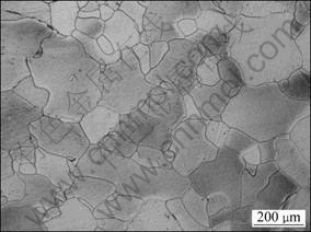
Fig.1 Microstructure of as-annealed pure iron
3 Results
3.1 Cross-section observation
The cross-sectional microstructures of pure iron after impact by steel projectile of 2.8 km/s are shown in Fig.2. Very fine grain region with about 400 ��m in width from the crater bottom is shown in region A of Fig.2(a). Unlike the narrow softened zone induced by dynamic recrystallization[10] or equiaxed and spherical grains by melting[9], special lamellar-shape fine grain structure is composed of irregular elongated spherical grains arranging along the direction of flow lines (Fig.2(b)). The material just near the fine grain region is strongly compressed, showing damage region as deformation bands (region D of Fig.2(a)). With increasing the distance away from the crater, the width of the deformation bands increases gradually, showing that the shock wave attenuates when propagating in the target. Figures 2(c) and (d) show the high magnification micrographs of the transition region (C) and deformation bands region (D) in Fig.2(a), 400 ��m and 600 ��m away from the crater bottom respectively. The combination of deformation bands is the bundle of lamellar structures. The original size of grains along the impact direction perpendicular to deformation bands is about 200 ��m, after impact the average width of the lamellar structures is about 10 ��m (Figs.2(c) and (d)), indicating that the compressive deformation strain is at least 95%. The microstructure of transition region (Fig.2(c)) is the more severe deformed lamellar structure compared with deformation band region (Fig.2(d)). The widths of these lamellar structures do not distribute continuously, inferring the localized plastic deformation. The fine substructures inside the lamellar are extended along the whole band in the transition region, in contrast, with no substructures in deformation bands region.
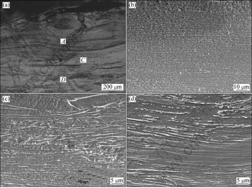
Fig.2 Cross-section observations of pure iron after impact: (a) Optical micrograph; (b) SEM micrograph showing fine grain region A; (c) SEM micrograph showing transition region C; (d) SEM micrograph showing deformation band region D
3.2 Microstructure observed by TEM
The results above clearly demonstrate that fine grain structures develop at the crater bottom of the pure iron target during impact. With the distance away from crater bottom increasing, the strain decreases from the crater bottom to matrix. The corresponding microstructure characteristics in different regions are signs of the microstructure evolution. Therefore, detailed TEM observations were performed from the deformation bands region to crater bottom to demonstrate the process of grain refinement.
Figure 3 shows the TEM observations in the deformation layer in deformation band region (D in Fig.2(a)), in which typical deformation induced microstructure features are detected. The deformation band consists of very fine parallel lamellar blocks with thickness of 100-300 nm. Most of these lamellar blocks are elongated with misorientations varying from a few degrees to a few tens of degrees (as evidenced by SAED pattern). Some of these boundaries are developed from original dense dislocation walls (DDWs). DDWs are believed to result from dislocation accumulation and rearrangement for minimizing the total energy state. High-density dislocations arraying in tangles are observed in association with lamellar blocks. The dislocation distribution is not uniform and randomly arranged.
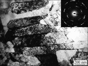
Fig.3 TEM image showing lamellar blocks with DDWs in deformation band region
As the distance decreases, dominant microstructure changes with the increase in deformation strain and strain rate. Most original grains are observed to be subdivided into lamellar blocks (Fig.4(a)). The width of the lamellar-shape structures is almost the same with that in Fig.3, but the length is much longer than that in Fig.3. Those very flat blocks are sandwiched by lamellar dislocation boundaries that have replaced the small strain DDWs. In contrast to the small strain lamellar blocks, the cell blocks at the large strain are usually discontinuous. Strips of equiaxed subgrains are always observed in lamellar blocks at large strains (Fig.4(a)). Those lamellar blocks are separated by sharper and thinner boundaries and the misorientations across them are much larger (as evidenced by SAED pattern in Fig.4(a)). It is rational to understand that those boundaries are developed from original DDWs by accumulation and annihilation of more dislocations, which increases their average misorientation angle and decreases their spacing with increasing strain and strain rate[11]. With increasing the strain continuously, DDWs may transform into small-angle grain boundaries by absorbing more and more dislocations.
Simultaneously, different oriented lamellar blocks also appear and intermix with other lamellar blocks at the crater bottom, which results in further refinement of the cells by cutting the lamellar blocks into smaller cells. In some places, the smaller cell was presented as submicron polygonal cells (cells 1-6 in Fig.4(b)). Cells 1 and 2 are subgrains with distinct boundaries which may be developed from DDWs. The boundaries around cells 3 and 4 are not well-defined still like DDWs, as well cell 4 rotates to another direction not along the direction of two lamellar blocks. Development of some new boundaries from DDWs is seen in progress, e.g. cells 5 and 6, as indicated in Fig.4(b). The specific microstructures in the lamellar-shaped cells are polygonal cells separated by subboundaries or DDWs, so dense dislocations distribute inside polygonal cells and dislocation tangles exist near the boundaries. Dislocation tangles and DDWs will develop to subboundaries by accumulating more dislocations and dense lattice dislocations may involve in further refinement of the cells with increasing strain. With increasing the strain, more and more small polygonal cells with random orientations will occur.
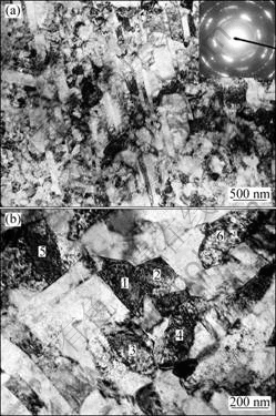
Fig.4 TEM images showing transition region: (a) Lamellar structure with strips of equiaxed subgrains; (b) Intersect lamellar structures forming submicron polygonal cells with subboundaries and DDWs
The deformation strain and strain rate are drastically increased just close to the crater bottom. In this layer, equiaxed grains are seen with grain size of about 100 nm (Fig.5). The lamellar blocks are present at the edge of this section, and the equiaxed grains seem to be arranged in parallel arrays. Apparently, those equiaxed grains are formed by breaking up the lamellar blocks due to dislocation motion and subboundary development. The continuous diffraction rings in the SAED pattern in Fig.5 indicate that randomly oriented grains were obtained.
Figure 6 illustrates residual microhardness profiles extending along the impact axes from the crater bottom to the matrix. From this figure, the thickness of the deformation bands area can be identified to be about 900 ��m. In addition, it can be seen that the residual microhardness outward from the crater bottom is about twice that of matrix without any softening. It implies that the ultrafine equiaxed grains can form even though there is still a high strain in the surrounding area corresponding to some equiaxed grains formed and companied by dense dislocations, dislocation tangles, DDWs and subboundaries.
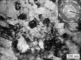
Fig.5 TEM image showing equiaxed grains separated by large misorientation boundaries
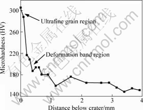
Fig.6 Residual Vickers microhardness profiles versus distance from crater bottom
4 Discussion
4.1 Development of DDWs
Spherical shock wave can form and propagate in the target by spherical projectile impact. Different dislocation characteristics can be induced by shock wave. Dislocations in BCC metals tend to be more uniformly distributed at a low strain level in shock loading[2]. The predominant substructure is dislocation tangle which appears to be fairly uniformly distributed overall with no well-defined cell structures. This randomly distributed dislocation and dislocation pile-up are called medium energy dislocation structures (MEDS) and high energy dislocation structures (HEDS)[12]. With decreasing the distance from crater bottom, dislocations structure may change to decrease internal energy. An increasing dislocation density is observed which gives rise to the formation of lamellae structure shown in Figs.3 and 4. These lamellae structures are always composed of dense dislocation walls (DDWs) or dislocation tangles (DTs), which are very similar to the microstructure during cold rolling, low energy dislocation structures (LEDS)[12]. Low energy dislocation structures are stress screened by definition. It means that the range of the stress field of the average dislocation in a LEDS extends more or less only to the nearest neighbor dislocations[12]. Dislocations must arrange themselves by the resolved shear stress component to stationary state with low energy level. Consequently, uniformly distributed dislocation substructure may evolve to low energy dislocation structure such as DDWs and DTs. Development of these configurations results in subdivision of original grains separated by DDWs and DTs.
The spacing of DDWs is related to the dislocation cell dimension (L), as a function of acting shear stress (��), L=10Gb/�� (G is the shear modulus and b the Burgers vector)[13]. The dislocation cell size shrinks with increasing flow stress. The width of lamellar bands decreases as the stress increases gradually along the impact direction from matrix to crater bottom. The spacing of DDWs is 100-300 nm. Figure 4 apparently illustrates that the shear stress and the dislocation density at the crater bottom are very high.
The multi-directional lamellar structures which may be induced by spherical shock wave were observed at the crater bottom (Fig.4). The crater bottom is just beneath the impact point and the origin of spherical shock wave. The distribution of stress in the target is axisymmetric, and the crater bottom is located at the axis of symmetry. The different stress may lead to the change of slip systems even inside the same grain. The dislocations interact with other dislocations in different slip systems, and the dislocation tangles may form the dislocation cell boundaries. With increasing the plastic strain, the cell boundaries may arise from the mutual trapping of dislocations into low energy configurations[14]. Therefore, the radial lamellar structure is formed and interacts with each other at crater bottom. This configuration can subdivide grains more efficiently compared to other simple deformation such as rolling and torsion.
4.2 Formation of ultrafine grains
Figure 5 illustrates that the ultrafine grain with grain size of about 100 nm formed at the crater bottom. The continuous diffraction rings in the selected area diffraction pattern in Fig.5 indicate that randomly oriented grains were obtained. Some researches indicate that the formation of ultrafine grains at hypervelocity impact is dynamic recrystallization (DRX) with the impact velocity of 3.3 km/s corresponding to the shock pressure of 89 GPa[8]. The narrow dynamic recrystallized zone was observed in the iron target with the impact velocity of 3.3 km/s. The impact velocity of 3.3 km/s is higher than 2.8 km/s presented in this work. The shock pressure at the instant of impact is 89 GPa, also higher than 68 GPa in this work.
The difference of shock pressure could induce dissimilar deformation microstructure since the stress, strain rate and plastic strain may vary with shock pressure. Large stress can act more dislocations to subdivide and diminish the width of cell. The refined subgrains with high energy may induce the nucleation of recrystallization. Strain rate plays a key role in refining grains into the nanometer region[15]. The different severe plastic processes, such as ECAP, HPT and SMAT, have different residual grain sizes due to the different strain rates. Plastic strain at crater bottom can produce huge temperature rise. The following equation is applied to calculating the temperature rise:
![]() (1)
(1)
where �� is the fraction of plastic deformation work converted to heat, here ��=0.9; �� is the density of the material; and cp is the specific heat capacity. The temperature rise under hypervelocity impact condition almost comes from the adiabatic plastic deformation depending on strain by Eq.(1). With increasing the impact velocity, the plastic strain increases. When the temperature rise induced by the strain with high velocity reaches (0.5-0.6)Tm, dynamic recrystallization may happen[16].
It can be noted that in Ref.[8] the fine grain zone at crater bottom is softer than the heavily deformed regime nearby. The grain size of narrow dynamic recrystallized zone is 300-500 nm. But in this work, the microhardness of fine grain zone is higher than the heavily deformed regime nearby and the grain size of fine grain zone is just about 100 nm. These dissimilarities of refine grain zone are produced by different impact velocities. Higher velocity corresponding to higher shock pressure can form larger strain and strain rate. This may result in higher energy which has higher possibility to form ultrafine grains by dynamic recrystallization. The grains with elimination of strain formed during dynamic recrystallization and grain growth at higher temperature cause the soften effect at the crater bottom. In this work, the fine grains form in the grain refine process just through plastic deformation. The dynamic recrystallization does not appear or just starts due to the lower impact velocity. It should be mentioned that severe plastic deformation can refine the grains, but with the increase of impact velocity, the grains from dynamic recrystallization will be domain in the microstructure at the crater bottom.
5 Conclusions
1) Ultrafine grain structure with an average grain size of 100-200 nm was obtained at the crater bottom of pure iron target by impact at the velocity of 2.8 km/s. The distribution of ultrafine grain region is 0-400 ��m away from crater bottom, and the severe deformation band region is 400-900 ��m away.
2) Based on the microstructure observation, a grain refinement process induced by plastic deformation during hypervelocity impact in pure iron is proposed. The process can be divided into three steps. Dislocation induced by spherical shock wave has a tendency to form low energy dislocation structures (LEDS), such as DDWs and DTs, to refine the original grains and form lamellar structure. The DDWs and DTs transform into subboundaries which separate lamellar structure to cells. Evolution of subboundaries to high misorientation grain boundaries leads to the formation of ultrafine grains.
References
[1] BAKER R, PERSECHINO A. An analytical model of hole size in finite plates for both normal and oblique hypervelocity impact for all target thicknesses up to the ballistic limit [J]. International Journal of Impact Engineering, 1993, 14: 73-84.
[2] HUANG J C, GRAY G T ��. Substructure evolution and deformation modes in shock-loaded niobium [J]. Materials Science and Engineering A, 1988, 103: 241-255.
[3] FAN Ai-ling, LI Shu-kui, TIAN Wen-huai, WANG Fu-chi. Comparison of microstructures in electroformed and spin-formed copper liners of shaped charge undergone high-strain-rate deformation [J]. Transaction of Nonferrous Metals Society of China, 2007, 17: 1447-1450.
[4] YANG Yong-biao, WANG Fu-chi, TAN Cheng-wen, WU Yuan-yuan, CAI Hong-nian. Plastic deformation mechanisms of AZ31 magnesium alloy under high strain rate compression [J]. Transaction of Nonferrous Metals Society of China, 2008, 18: 1043-1046.
[5] ESQUIVEL E V, MURR L E. Grain boundary contributions to deformation and solid-state flow in severe plastic deformation [J]. Materials Science and Engineering A, 2005, 409: 13-23.
[6] MURR L E, GARCIA E P; FERREYRA E T, NIOU C S, RIVAS J M, QUI S A. Microstructural aspects of hypervelocity impact cratering and jetting in copper [J]. Journal of Materials Science, 1996, 31: 5915-5932.
[7] MURR L E, BUJANDA A A, TRILLO E A, MARTINEZ N E. Deformation twins associated with impact craters in polycrystalline iron targets [J]. Journal of Materials Science Letters, 2002, 21: 559-563.
[8] MURR L E, TRILLO E A, BUJANDA A A, MARTINEZ N E. Comparison of residual microstructures associated with impact craters in fcc stainless steel and bcc iron targets: the microtwin versus microband issue [J]. Acta Materialia, 2002, 50: 121-131.
[9] ZHEN L, LI G A, ZHOU J S, YANG D Z. Micro-damage behaviors of Al-6Mg alloy impacted by projectiles with velocities of 1-3.2 km/s [J]. Materials Science and Engineering A, 2005, 391: 354-366.
[10] FERREYRA T E, MURR L E, GARCIA E P, HORZ F. Effect of initial microstructure on high velocity and hypervelocity impact cratering and crater-related microstructures in thick copper targets: Part I. Soda-lime glass projectiles [J]. Journal of Materials Science, 1997, 32: 2573-2585.
[11] DOHERTY R D, HUGHES D A, HUMPHREYS F J, JONAS J J, JENSEN D J, KASSNER M E, KING W E, MCNELLEY T R, MCQUEEN H J, ROLLETT A D. Current issues in recrystallization: A review [J]. Materials Science and Engineering A, 1997, 238: 219-274.
[12] KUHLMANN-WILSDORF D. Theory of plastic deformation: Properties of low energy dislocation structures [J]. Materials Science and Engineering A, 1989, 113: 1-41.
[13] KUHLMANN-WILSDORF D, van der MERWE J H. Theory of dislocation cell sizes in deformed metals [J]. Materials Science and Engineering, 1982, 55: 79-83.
[14] KUHLMANN-WILSDORF D, HANSEN N. Geometrically necessary, incidental and subgrain boundaries [J]. Scripta Metallurgica et Materialia, 1991, 25: 1557-1562.
[15] WANG K, TAO N R, LIU G, LU J, LU K. Plastic strain-induced grain refinement at the nanometer scale in copper [J]. Acta Materialia, 2006, 54: 5281-5291.
[16] MCQUEEN H J, JONAS J J. Recent advances in the hot working: Fundamental dynamic softening mechanisms [J]. Journal of Applied Metalworking, 1984, 3: 233-241.
��������ײ�´����а徧����ϸ������
�ߴ�𩣬�� ǿ��������
����������ѧ ����ѧԺ������ 100081
ժ Ҫ����������ײ���ڴ����а���ϵ��ӵײ��γ��˳�ϸ���ṹ��ͨ����ѧ����(OM)��ɨ��羵(SEM)����羵(TEM)�Ե��ӽ��治ͬ��ȴ�������֯���й۲�������õ������Ա���������ϸ���Ľ��ۡ����ȣ�������λ���ṹ(LEDS)������ܶ�λ��ǽ(DDWs)��λ������(DTs)���γɽ�ԭʼ�����ָ�Ϊ�����IJ�״�ṹ������Ӧ�������DDWs��DTs�ݻ�Ϊ���е�ȡ�����Ǿ��粢����״�ṹ�ָ�ΪϸС��״�ṹ���Ǿ���ת��Ϊ�߽ǶȾ��磬���յ��³�ϸ�����γɡ��Զ�̬�ٽᾧ�����У��ɳ���������²����ĸ�Ӧ���Ӧ���ʵ��µij�ϸ�����γɽ��������ۡ�
�ؼ��ʣ���������������ײ������ϸ��
(Edited by YANG Hua)
Corresponding author: XU Qiang; Tel: +86-10-68913365; Fax: +86-10-68912274; E-mail: xuq@bit.edu.cn
DOI: 10.1016/S1003-6326(11)60817-0
