

Deformation behaviors of magnesium alloy AZ31 sheet in cold deep drawing
YANG Lian-fa(������)1, MORI Ken-ichiro2, TSUJI Hirokazu2
1. School of Electromechnical Engineering, Guilin University of Electronic Technology, Guilin 541004, China;
2. Department of Production Systems Engineering, Toyohashi University of Technology,Toyohashi 441-8580, Japan
Received 5 March 2007; accepted 2 July 2007
Abstract:
To investigate how the popular magnesium alloy AZ31 sheet (aluminum 3%, zinc 1%) behaves in cold working, deep drawing experiments at room temperature, along with finite element(FE) simulation��were performed on the cold forming sheet of the AZ31 alloy after being annealed under various conditions. The activities were focused on the fracture pattern, limit drawing ratio(LDR), deformation load, thickness distribution, anisotropic effect, as well as the influences of the annealing conditions and tool configuration on them. The results display that punch shoulder radius instead of die clearance, has much influence on the thickness distribution. The anisotropy is remarkable in cold working, which adversely impacts the LDR. The fracture often happens on the side wall at an angle to axis of the deformed specimen. The results also imply that the LDR for the material under present experimental conditions is 1.72, and annealing the material at 450 �� for 1 h may be preferable for the cold deep drawing.
Key words:
AZ31 magnesium alloy; cold deep drawing; anisotropy; limit drawing ratio; finite element simulation;
1 Introduction
Owing to their low density, high specific strength and excellent behaviors in shock absorption, corrosion resistance, etc[1-2], magnesium alloys are ambitious materials for light construction components with the reputation of ��the metal of 20th century��[3-4], and have been increasingly applied to automobile and bicycle components, computer housing, cellular phone cover, etc[5-6]. Nowadays die-casting and die-forging are popular ways for manufacturing components of magnesium alloys. However, plastic forming technology is preferable for producing sheet cover components[7-8]. Magnesium alloys show excellent formability at elevated temperature of about 200 �� because non-basal slip systems become active in addition to basal slip, so sheet forming at elevated temperature, or warm forming becomes dominant nowadays[9-10]. However, during warm forming process the die and blank holder have to be heated while punch is needed to be kept cool, which makes the processing apparatus complicated and the initial investment high[11-12]. Moreover, magnesium alloys are easy to suffer from oxidation during warm forming[13]. Consequently, cold forming, e.g. deep drawing at room temperature is getting attractive[14]. Initial researches on this aspect are conducted by the Materials Forming Laboratory of Toyohashi University of Technology, Japan[15-16]. Up to now, however, there are few literatures concerning the cold deep drawing of magnesium alloy sheets. Hence, it is of great value to reveal the deformation behaviors so as to establish fundamental knowledge of the cold forming technology.
In this work, the deformation behavior of magnesium alloy AZ31 (aluminum 3%, zinc 1%) sheet in cold deep drawing was investigated by both the experimental approach and the finite element(FE) analysis, and emphasis was put on the fracture pattern, limit drawing ratio(LDR), deformation load, thickness distribution, anisotropic effect, as well as the influences of the annealing process and tool configuration.
2 Annealing process and tensile tests
2.1 Material and annealing
The magnesium alloy used in present experiment was AZ31 sheet (aluminum 3%, zinc 1%) of 0.5 mm in thickness, which was directly purchased from Japanese market.
Before the deep drawing experiments the AZ31 sheet blanks were annealed so as to improve its formability at room temperature. The annealing was completed in KDF-S90 (200 V, 50/60 Hz, 4 kW), an electric furnace produced by Sanyo-Denken Co. Ltd. For the sake of lessening the oxidation during the annealing process, each sheet blank was clamped by two thin stainless steel sheets and then packed well in aluminum foils. After being put into the electric furnace, the sheet blanks were heated within half an hour to the presetted annealing temperature and kept at that temperature for 1-3 h, and then were naturally cooled down in the electric furnace. The annealing conditions are listed in Table 1.
Table 1 Annealing conditions for AZ31 sheet blanks

2.2 Tensile tests and mechanical properties
In order to obtain stress��strain relationships that are taken as the material model for later finite element simulation, standard uniaxial tensile tests were conducted on AZ31 sheets prior to and after the annealing process, respectively. The tensile tests were carried out on AGS-J-50kN, a Precision Universal Tester produced by Shimadzu Corporation. The stress��strain curves and mechanical parameters of AZ31 sheets under different annealing conditions are shown in Fig.1 and listed in Table 2, respectively.
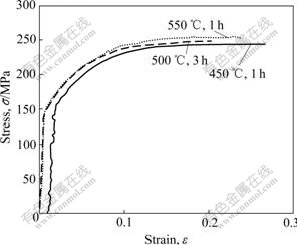
Fig.1 Stress��strain curves of AZ31 sheets obtained from tensile tests
Table 2 Mechanical properties of AZ31 sheet after annealed
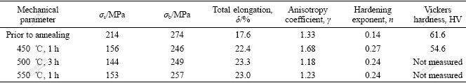
As shown in Fig.1, the stress��strain curves of AZ31 sheets are close to each other irrespective of the annealing conditions. This implies that the effect of annealing conditions on the stress��strain curve is not remarkable. On the other hand, referring to Table 2, it is observed that the yield strength (��s), the ultimate tensile strength(��b) and the Vickers hardness decrease to some extent after annealing, contrary to the strain hardening exponent and total elongation. Anisotropy coefficient, ��, increases with annealing temperature and annealing time, but changes slightly when the annealing temperature is 500 �� or higher. With respect to the anisotropy, high annealing temperature seems preferable. However, since the oxidation at elevated temperature close to melting point becomes severe, the most appropriate annealing condition for AZ31 sheet, in view of practicability, is at 450 �� for 1 h.
3 Experimental work of cold deep drawing
The experiment was performed so as to investigate the deformation load, fracture pattern, LDR and thickness distribution.
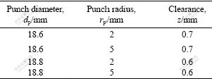
The working part of the experimental tool for cold deep drawing is shown in Fig.2. The diameter of the die cavity Dd is 20 mm, and the die shoulder radius rp is 4 mm in any case. The diameter of the pouch dp is 18.6 mm or 18.8 mm to produce two kinds of die clearances, as shown in Table 3. The diameter of sheet blank D0 is 32 mm or 33 mm.

Fig.2 Schematic diagram of tool configuration for cold deep drawing
Table 3 Measurements of working parts of experimental tool
Previous research displays that the LDR of AZ31 sheet with lubricant MoS2 is higher than that with lubricant aluminum oil or Teflon sheet[16]. Consequently in the experiment the blank holder and die other than the punch were uniformly greased by MoS2. Previous research also displays that the LDR for the AZ31 sheet will not change obviously when blank holder force(BHF) is over 3 kN, so an initial BHF of 1kN was adopted in deep drawing experiments.
The cold deep drawings were carried out on AG-IS-250kN, a Precision Universal Tester produced by Shimadzu Corporation. During the drawing process the ram of the tester moved at the rate of 1 mm/s and the load-stroke curves were automatically recorded by the tester. After the deep drawing, measurements of the thickness and the cup height were conducted with digital micrometer by sectioning the drawn specimen symmetrically.
4 Finite element model
In order to clearly display the anisotropic effect of AZ31 sheet in cold deep drawing, FE simulations were performed on the forming process using an explicit dynamic code DYNAFORM.
Fig.3 shows the geometrical FE model, in which only a quarter of the geometry is modeled with adoption of symmetric constraint due to the axisymmetric specimen. The model is coincident with experimental tool configuration well except that the punch is upside in the FE model. In simulation the sheet blank was assumed to be homogeneous and incompressible but anisotropic in deformation behavior. The strain��stress curves experimentally obtained as shown in Fig.1 are employed as the material model of the simulation. The other two parameters required for the simulations are the elastic modulus(E) and Poisson ratio(��), which were set to be 210 GPa and 0.33, respectively. The sheet blank was meshed by shell element of 0.1-0.2 mm, while the punch, the die and the blank holder were modeled as rigid elements with friction coefficients of 0.15, 0.05 and 0.05, respectively. The friction conditions accord basically with those in the deep drawing experiments.

Fig.3 Quarter model of FE simulation: (a) Before mesh; (b) After meshed
5 Results and discussion
5.1 Fracture pattern
Fig.4 exhibits the well-formed and fractured specimens. Some of the cups fractured at the punch shoulder, similar to the ordinary metal sheet; nevertheless most cups fractured at side wall in the late stage of the forming with the crack at an angle to axis of the deformed specimen[15]. This is one of the remarkable characteristics of magnesium alloy sheet in cold deep drawing.

Fig.4 Well-formed specimen (a) and fractured pattern (b)
5.2 LDR
Drawing ratio is commonly expressed by Rd= D0/d, where d is the inner diameter of the deformed specimen. The Rd should be equal to punch diameter dp if the spring-back is neglected. LDR is the one when the specimen is on the verge of fracture.
All the specimens of D0=33 mm (Rd=33/18.8=1.76) fractured during the deep drawing irrespective of the annealing conditions listed in Table 1. As for the specimen of D0=32mm (Rd=32/18.8=1.72), all specimens annealed with 400 �� fractured; a minority of specimens annealed with 450 ��, 1 h fractured; a greater majority of specimens annealed with 500 ��, 1 h or 550 ��, 3 h fractured in the deep drawing; but all specimens annealed with 500 ��, 3 h or 550 ��, 1 h succeeded. It can be concluded that the LDR of AZ31 sheet is 1.72 under present experimental conditions. The following discussion will focus on the specimen of D0=32mm annealed with 450 ��, 1 h, 500 ��, 3 h and 550 ��, 1 h, respectively.
5.3 Deformation load
Fig.5 illustrates the deformation load��stroke curves of AZ31 sheet in cold deep drawing. It is observed that two peaks appear when the die clearance is small (z=0.6 mm), in contrast with one peak when it is big (z=0.7 mm). The first peak, or the maximum deformation load appears at the stroke of about 6 mm, which is the result of joint action of the ��strengthening effect�� due to working hardening and ��softening effect�� caused by flange shrinking during the deep drawing process. The ��softening effect�� is dominant prior to the peak, whereas overwhelms after that, so the deformation load culminates somewhere during the deep drawing process. On the other hand, the flange gets thicker during the deep drawing process and the resistance to flowing of the material into the die cavity through a small clearance (dp=18.8 mm) then gets higher, thus a bigger deformation load is required and the second peak inevitably appears. For the same reason, no second peak appears if the die clearance is big enough (e.g. z=0.7 mm). This finding suggests that the load can be reduced and LDR can be increased somewhere with appropriate increase of die clearance.
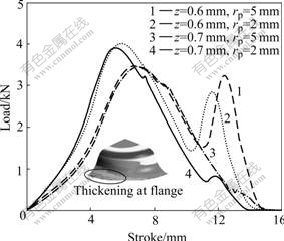
Fig.5 Curves of load vs stroke (450 ��, 1 h, D0=32 mm)
Fig.5 also reveals that punch shoulder radius (rp=2 mm or 5 mm) has stronger influence on the second peak than on the first peak.
5.4 Thickness distribution
In the case of a big die clearance (e.g. z=0.7 mm), both the maximum thickness at the cup edge and minimum thickness at the ��dangerous section�� near the punch shoulder (It is so called because fracture often happens there) are big, as shown in Fig.6. One reason may be that while the thick flange is forced into the die cavity, it is compelled to get thinner and equal to the die clearance if the spring-back is ignored, consequently a bigger clearance results in a bigger thickness at the cup edge. On the other hand, a bigger clearance may reduce the flow resistance of the material into the cavity and the pull force at ��dangerous section��, resulting in a small deformation in thickness there. This implies that the possibility of fracture around the punch shoulder can be reduced with the appropriate increase of the die clearance. However, it must be noted that a big die clearance may result in a severe difference between the maximum and minimum thicknesses, or a non-uniform strain distribution in thickness.

Fig.6 Distribution of thickness strain from axis of specimen (450 ��, 1 h, D0=32 mm)
The location of ��dangerous section��, i.e. the thinnest location, is evidently affected by the punch shoulder radius instead of the die clearance. The smaller the punch shoulder radius, the farther the ��dangerous section�� from the axis of the specimen and the thinner the wall at this position. This result can be explained by the fact that a small punch shoulder radius increases the bending deformation and the flow resistance of material as mentioned above.
5.5 Anisotropic effect
The simulated thicknesses are in good agreement with experimental data (test), as shown in Fig.7, which indicates that the FE model is accurate enough. It can be observed that anisotropy results in the different thickness distribution at the different directions of 0?, 45? and 90? in the sheet plane.
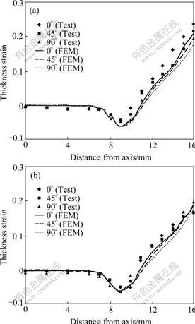
Fig.7 Influence of anisotropy on thickness distribution: (a) 500 ��, 3 h; (b) 550 ��, 1 h
Another outstanding effect by anisotropy is that it makes the material flow into the die cavity at different rates during the deep drawing process. This results in different thicknesses at flange (Fig.8) and an ��earing phenomenon��, i.e. uneven edges of the cup specimen (Fig.9). The edge unevenness and thickness non- uniformity of the specimen with ��=1.23 (450 ��, 1 h) are more evident than those of the specimen with ��=1.23 (550 ��, 1 h). In other word, the former is easy to fracture at sidewall surface.

Fig.8 Anisotropy behavior in thickness distribution: (a) 450 ��, 1 h (��=1.68); (b) 550 ��, 1 h (��=1.23)

Fig.9 Height difference at cup edge deduced by anisotropy behavior (values in brackets are obtained by simulation): (a) 450 ��, 1 h (��=1.68); (b) 550 ��, 1 h (��=1.23)
6 Conclusions
1) Anisotropy of AZ31 sheet is remarkable in cold deep drawing, which adversely impacts on the LDR. The anisotropy of the sheet in cold deep drawing can be abated by annealing, and the annealing at the temperature of 450 �� for 1 h may be preferable.
2) The fracture often happens at the sidewall with the crack at a certain angle to the axis of the deformed specimen. This is obviously different from that of common metals.
3) Punch shoulder radius instead of die clearance has great influence on the minimum thickness and its location. Deformation load and fracture possibility around the punch shoulder can be reduced with the appropriate increase of die clearance, but risking a severe non-uniformity in the thickness distribution.
4) The LDR of AZ31 sheet under present experimental conditions is 1.72. In order to increase the formability of the sheet, further research should be focused on the improvement of material properties of the raw sheet rather than on the deep drawing process itself.
Acknowledgements
The experimental and simulation works were completed in the Materials Forming Laboratory of Toyohashi University of Technology, Japan. The first author of this paper would like to acknowledge the support of the Laboratory in providing the experimental material, the experimental tool and forming conditions. The first author also would like to acknowledge the care guidance of Pro. MORI Ken-ichiro while conducting the research work as a visiting scholar in his laboratory in 2006.
References
[1] ELIEZER D, AGHION E, FROES F H. Magnesium science, technology and application [J]. Advanced Performance Materials, 1998, 5(3): 201-212.
[2] ABBOTT T, KAMAD S, KOIKE J, KDND H K, KAWAMURA Y. Magnesium research trend in Japan [J]. Materials Science Forum, 2003, 419/422: 21-24.
[3] MORDIKE B L, EBERT T. Magnesium properties��Applications potential [J]. Mater Sci Eng A, 2001, 302: 37-45.
[4] AGHION E, BRONFIN B, ELIEZER D. The role of the magnesium industry in protecting the environment [J]. J Mater Process Technol, 2001, 117(3): 381-385.
[5] QI Qing-ju, LIU Yong-bing, YANG Xiao-hong. The research on magnesium alloys and their applications prospect in automotive industry [J]. Automotive Engineering, 2002, 24(2): 94-100, 125.
[6] YUAN Xu-di. The application prospects of magnesium alloys in the automobile industry [J]. Nonferrous Metals Processing, 2002, 31(1): 14-17.
[7] HARADA G. Forging of magnesium alloys [J]. Press Technology, 2004, 42(2): 63-68. (in Japanese)
[8] YAMASAKI E, TAHEN K, SAKAWA O. Warm processing of magnesium alloys [J]. Press Technology, 2004, 42(2): 43-45. (in Japanese)
[9] ZHANG S H, ZHANG K, XU Y C, WANG Z T, XU Y, WANG Z G. Deep-drawing of magnesium alloy sheets at warm temperatures [J]. J Mater Process Technol, 2007, 185(1/3): 147-151.
[10] WANG Ling-yun, SONG Mei-juan, LIU Rao-chuan. Superplasticity and superplastic instability of AZ31B magnesium alloy sheet [J]. The Chinese Journal of Nonferrous Metals, 2006,16(2): 327-332. (in Chinese)
[11] CHEN F K, HUANG T B, CHANG C K. Deep drawing of square cups with magnesium alloy AZ31 sheets [J]. International Journal of Machine Tools & Manufacture. 2003, 43(15): 1553-1559.
[12] CHANG Qun-feng, LI Da-yong, PENG Ying-hong. Experimental and numerical study of warm deep drawing of AZ31 magnesium alloy sheet[J]. International Journal of Machine Tools & Manufacture, 2007, 47(3/4): 436-443.
[13] NGAILE G, ALTAN T. Finite element simulation of magnesium alloy sheet forming at elevated temperatures [J]. J Mater Process Technol, 2004, 146(1): 52-60.
[14] WAGENER H W, HOSSE-HARTMANN J, FRIZ R. Deep drawing and impact extrusion of magnesium alloys at room temperature [J]. Advanced Engineering Materials, 2003, 45(4): 237-242.
[15] MORI K, TSUJI H, HARADA Y. Cold deep drawing of AZ31 Magnesium alloy [C]// The Proceedings of the 2005 Japanese Spring Conference for the Technology of Plasticity. Japan: Sanjyo, 2005: 229-230.
[16] TSUJI H AND MORI K. Effect of lubricants on cold deep drawing of AZ31 Magnesium alloy sheet [C]// The Proceedings of the 56 Japanese Joint Conference for the Technology of Plasticity. Japan: Okinawa, 2005: 141-142.
Corresponding author: YANG Lian-fa; Tel: +86-773-2951235; E-mail: y-lianfa@163.com
