

Numerical simulation of jet breakup due to amplitude-modulated (A-M) disturbance
LUO Jun(�� ��)1, QI Le-hua(���ֻ�)1, 2, LI Li(�� ��)1,
YANG Fang(�� ��)1, JIANG Xiao-shan(��Сɺ)1
1. School of Mechatronic Engineering, Northwestern Polytechnical University, Xi��an 710072, China;
2. Key Laboratory of Contemporary Design and Integrated Manufacturing Technology,
Ministry of Education, Northwestern Polytechnical University, Xi��an 710072, China
Received 23 May 2007; accepted 19 December 2007
Abstract:
In order to characterize the mechanics of jet breakup, the finite volume formulations were employed to solve the Navier-Stokes equations and continuity equation of jet. The volume of fluid(VOF) method was used to track the free surface of jet. The spray process of the molten Pb63Sn37 alloy was simulated based on the mathematical model by means of FLUENT code. The configuration of jets generated in different disturbance ratios and modulation ratios was obtained. The theoretical results show that the droplets merge together by the number of disturbance ratio N, which agrees with the corresponding picture captured in the experiment. In addition, the droplet streams broken at non-optimal frequency are also uniform according to simulation results, which proves that the A-M disturbance can increase the width of the uniform droplet generating frequency.
Key words:
amplitude-modulated(A-M) disturbance; jet; finite volume formulation; uniform droplet stream;
1 Introduction
The uniform metal droplet deposition technology has emerged as one efficient net forming technology of metal parts[1-2]. This technology, like the ink-jet printing, deposits micro metal droplets instead of liquid ink onto substrate to build three-dimensionally physical parts[3-5]. The key factor of the metal droplet deposition technology is to generate the uniform droplets. The conventional method for generating uniform droplets uses sinusoidal disturbance to break the jet at optimal frequency[6-7]. The frequency of disturbance must be adjusted carefully near optimal frequency for uniform droplet generation and the droplet size can not be ��customized�� when the size of orifice is chosen.
A nonconventional droplet generation technology using the amplitude-modulated(A-M) disturbance has been developed by ORME et al[8-9] to solve those problems. Compared with the conventional disturbance, this technology can generate a more flexible and controllable uniform droplet stream. The predict method for jet breakup forced by amplitude-modulated(A-M) disturbance is based on RAYLEIGH linear theory, which is only an approximate method and cannot predict more complex condition. So the parameters of jet breakup (like jet breakup length, droplet diameter) are still obtained from experiment.
The mathematical model of jet breakup is developed in order to characterize the mechanics of jet breakup forced by A-M disturbance accurately. The jet breakup process and droplet mergence are simulated by the volume of fluid(VOF) method based on this model. The effects of the frequency and the frequency ratio on the droplet streams were analyzed in this work.
2 Background
The phenomenon of droplet formation from laminar jet was initially described mathematically by RAYLEIGH who solved the non-viscous axisymmetric fluid jet breakup problem by linear instability theory[10]. Then WEBER[11] extended RAYLEIGH��s analysis to viscous liquids, which led to a detailed expression including liquid viscosity. When the viscous liquid is ejected, the N-S equations and the continuity equation can be expressed as
![]()
![]() (1)
(1)
![]()
![]() (2)
(2)
![]() (3)
(3)
where ur and uz are jet liquid velocities in the axial and radial direction; r is the density of the liquid and m is the viscosity of liquid. In Weber��s linear instability theory, the pressure p is expressed as
![]() (4)
(4)
where ![]() is the pressure of jets; p(r)exp(wt)sin(ikz) is the disturbance of velocity; w and k are the growth rate and wave number, respectively. The radial disturbance on the circumference of jet grows exponentially in time as exp(wt). After solving the N-S equations and the continuity equation of jet, the growth rate w can be expressed as
is the pressure of jets; p(r)exp(wt)sin(ikz) is the disturbance of velocity; w and k are the growth rate and wave number, respectively. The radial disturbance on the circumference of jet grows exponentially in time as exp(wt). After solving the N-S equations and the continuity equation of jet, the growth rate w can be expressed as
![]() (5)
(5)
where Rj is the jet radius; k*=2��Rj/�� is the nondimensional wave number. From the partial differential of Eqn.(3) with respect to k*, the fast disturbance growth rate wopt can be obtained:
 (6)
(6)
For analyzing the breaking of jet in the non-optimal condition, the jet nonlinear instability theory was developed by PIMBLEY and LEE[12] and the satellite droplet phenomenon was studied. KAN and CHEN[13] employed commercial CFD software (CFD-ACE+) to simulate the metal jet breakup. LI et al[14] employed the FLUENT code to simulate the breakup of the conventional breakup of the uniform droplet stream, and these theoretical results are more accurate than the predictions from linear instability theory. Those methods are more accurate than the linear instability theory.
When jet is forced by A-M disturbance, the pressure can be expressed as
p(t)=p0+��p(1+msin��mt)sin��ct (7)
where ��c is the angular frequency of carrier wave; ��m is the angular frequency of modulation wave; m is the ratio of modulation to carrier amplitudes.
For analyzing the breaking of jet forced by A-M disturbance accurately, the finite volume formulations were employed to simulate the process of jet breakup, and the VOF method was utilized to trace free surface of jet.
3 Mathematical formulations
The laminar jet is free-surface flow. In this work, the N-S equations and continuity equation of jet (Eqns.(1)-(3)) are solved by finite volume formulations. The surface of jet, tracked by VOF method is re- constructed by Young��s interface construction algorithm. The simulation is realized using the FLUENT code.
In FLUENT, the surface tension model is the continuum surface force(CSF) model. The volume force is added to the momentum equation as source item. The volume force can be expressed as
 (8)
(8)
![]() and
and ![]() are defined as the gradient and the curvature of the ith phase flow on the surface, respectively; ��ij is the tension of free-surface and ��a is the volume-averaged density on the surface.
are defined as the gradient and the curvature of the ith phase flow on the surface, respectively; ��ij is the tension of free-surface and ��a is the volume-averaged density on the surface.
The free-surface is defined by solving the function of volume in the mesh cells[10]. If the whole calculation domain is ��, the domain of flow A is ��1, and the domain of flow B is ��2, so, a function can be defined as
![]() (9)
(9)
Cij is defined as the integration of ��(x, t) in the mesh cell Iij (assuming that the mesh is rectangle).
![]() (10)
(10)
where Cij is the fluid volume fraction function, and it satisfies the Eqn.(11), which is the equation of VOF[15]:
![]() (11)
(11)
4 Treatment on key problems
The physical model shown in Fig.1 is built according to the experimental apparatus used in Ref.[9]. In order to improve the efficiency and accuracy of simulation, the unstructured and structured meshes are employed in the crucible domain and the jet domain, respectively. Since the jet keeps axisymmetrical in the breakup, the simulation can be simplified to an axisymmetrical problem. The size of jet domain is about 10 cm in length and 0.5 cm in width. The size of crucible domain is the same with the physical model shown in Fig.1. The whole mesh and local mesh of the orifice are shown in Fig.2.
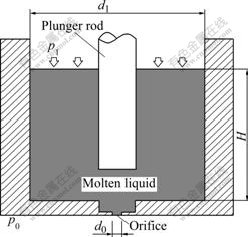
Fig.1 Schematic diagram of crucible
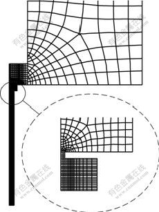
Fig.2 Local mesh of simulation domain and orifice
The boundary conditions are shown in Fig.3. The inlet has a constant pressure pl that is also the spray pressure used in Ref.[9]. The outlet pressure p0 is equal to one standard atmospheric pressure. The Wall 1 and Wall 2 are considered as the smooth walls. The disturbance will be loaded to the liquid by defining the motion of the wall 2.
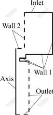
Fig.3 Setting of boundary conditions
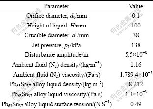
The jet material is the Pb63Sn37 alloy. This alloy is heated to 473 K in the spray process and maintains liquid in the spray process. The liquid temperature isn��t taken into consideration in the calculation. The parameters of spray conditions and the properties of the material are listed in Table 1.
Table 1 Parameters of spray condition and properties of material[9]
When the jet was established, the A-M disturbance was applied to the jet by the user-defined interface function of the FLUENT on the Wall 2. The carrier and modulation wave of A-M disturbance are sinusoid waves. The A-M wave is expressed as
Dwave=Ac[1+msin(2��fmt)]sin(2��fmt) (12)
where m is the degree of modulation; N=fc/fm represents the ratio of carrier frequency to modulation frequency. The carrier wave with frequency of 12 kHz is shown in Fig.4(a); the modulation wave is shown in Fig.4(b); the A-M wave with m of 0.5 is shown in the Fig.4(c). The carrier wave is enveloped by modulation wave. The amplitude of carrier wave presents periodical variety with the modulating wave waveshape.
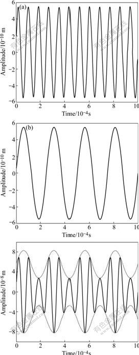
Fig.4 Shapes of A-M wave: (a) Carrier wave; (b) Modulation wave; (c)A-M wave
5 Results and discussion
The comparison of the simulation results and the pictures captured in the experiment is shown in Fig.5. In the experiment[9], after the metal is melted in the crucible, the liquid is ejected from the diameter of 0.1 mm orifice under the pressure of 138 kPa. The external A-M distance agitated by the piezoelectric crystal is transferred into metal liquid by a plunger rod which is Wall 2 in the boundary conditions. The carrier frequency of this disturbance is 12 kHz; the ratio of modulation m is 0.5 and the frequency ratio N is 1, 2 and 3 in the right picture of Figs.5(a), (b) and (c), respectively. The unmerging droplet diameter estimated from the jet dia- meter is about 0.2 mm.
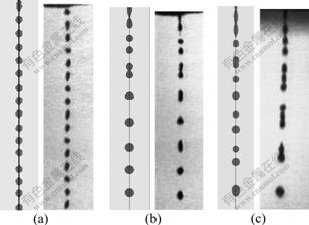
Fig.5 Droplet streams of different frequency ratios: (a) N=1; (b) N=2; (c) N=3
The simulation parameters described in the section 4 come from this experiment, and the simulation results (the left figure of Figs.5(a), (b) and (c)) show that the uniform droplets with diameter of 0.2 mm are obtained when frequency ratio N is 1 in Fig.5(a). Two or three such droplets merge into a large one when N is 2 or 3 in Figs.5(b) and (c).
Since the simplified model doesn��t take the factors, like the roughness of orifice surface, into consideration, the simulation results differ from the picture in the droplet shape. But the prediction of droplet pattern agrees with the picture. When the frequency ratio N of modulation is integer, the droplets merge together by the number of N, which proves that the method employed in this work is feasible.
The droplet streams, which are generated by the A-M disturbance with N of 3, m of 0.5 and three different carrier frequencies except the optimal one, are shown in Fig.6. It can be seen that only the merging location closes to the orifice when the carrier frequency increases, and three carrier droplets finally merge into one modulation droplet. Fig.7 shows that the separation of the adjacent droplets decreases by about 2 mm when the carrier frequency increases from 2.1 kHz to 3.0 kHz. The jets that are forced by conventional sinusoidal disturbance at frequency from 2.1 kHz to 3.0 kHz, will be non-uniform according to the jet instability theory. But the predictions in Fig.6 show that the droplet streams are uniform when the frequency of the carrier wave is non-optimal. It can be seen that the A-M disturbance can widen the range of frequency for uniform droplet stream generation and ��customize�� the droplet stream.

Fig.6 Droplet streams of different carrier frequencies: (a) fc=9.0 kHz; (b) fc=11.0 kHz; (c) fc=18.0 kHz
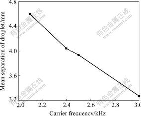
Fig.7 Curve of droplet separation vs carrier frequency
6 Conclusions
1) FLUENT code is employed to investigate the jet forced by A-M disturbance, in which carrier frequency is 12 kHz and frequency ratio N is 1, 2, 3. The prediction of droplet pattern agrees with the corresponding picture captured in the experiment. This method is useful for predicting the jet breakup with the A-M disturbance.
2) The uniform droplet streams are obtained and the droplet separation decreases when the carrier frequency increases from 2.1 kHz to 3.0 kHz. These results show that the carrier frequency of A-M disturbance for generating uniform droplets stream is not unique.
3) Compared with jet linear instability theory, a more accurate and convenient method that is valuable for analyzing the A-M disturbance is developed. It can be used to predict the parameters of droplet stream such as droplet breakup length and droplet size.
References
[1] CAO W, MIYAMOTO Y. Freeform fabrication of aluminum parts by direct deposition of molten aluminum [J]. Journal of Materials Processing Technology, 2006, 173(2): 209-212.
[2] TSENG A A, LEE M H, ZHAO B. Design and operation of a droplet deposition system for freeform fabrication of metal parts [J]. Journal of Engineering Materials and Technology, Transactions of the ASME, 2001, 123(1): 74-84.
[3] ANDO T, CHUN J, BLUE C. Uniform droplets benefit advanced particulates [J]. Metal Powder Report, 1999, 54(3): 30-34.
[4] SON H Y, NAH J W, PAIK K W. Formation of Pb/63Sn solder bumps using a solder droplet jetting method [J]. IEEE Transactions on Electronics Packaging Manufacturing, 2005, 28(3): 274-281.
[5] HAYES D J, WALLACE D B, COX W R. Micro jet printing of solder and polymers for multi-chip modules and chip-scale packages [C]// Proceedings of IMAPS International Conference on High Density Packaging and MCMS. Denver, 1999.
[6] FILLMORE G L, BUEHNER W L, WEST D L. Drop charging and defection in an electrostatic ink jet printer [J]. IBM Journal of Research of Development, 1977, 21(37): 37-47.
[7] ORME M, SMITH R. Enhanced aluminum properties by means of precise droplet deposition [J]. ASME Journal of Manufacturing Science and Engineering, 2000, 122: 484-493.
[8] LIU Q, LEU M C, ORME M. Amplitude modulated droplet formation in high precision solder droplet printing [C]// Advanced Packaging Materials Processes, Properties and Interfaces. Braselton, GA, 2001: 123-128.
[9] ORME M, COURTER J, LIU Q, HUANG C. Electrostatic charging and deflection of nonconventional droplet streams formed from capillary stream breakup [J]. Physics of Fluids, 2000, 12(9): 2224-2235.
[10] RAYLEIGH L. On the instability of jets [J]. Proc London Math Soc, 1878, 10: 4-13.
[11] WEBER C. Disintegration of liquid jets [J]. Z Angew Math Mech, 1931, 11(2): 136-159.
[12] PIMBLEY W T, LEE H C. Satellite droplet formation in a liquid jet [J]. IBM Journal of Research and Development, 1977, 21(1): 21-30.
[13] KAN H C, CHEN C C. Numerical analysis of effects of perturbation frequency on mono-sized droplet formation [C]// The 11th National Computational Fluid Dynamics Conference. Taiwan, 2004: 1-7.
[14] LI L, QI L H, YANG F, LUO J, JIANG X S. Numerical simulations of flow field and temperature field for droplet spray process [J]. Hangkong Xuebao/Acta Aeronautica et Astronautica Sinica, 2007, 28(3): 719-723. (in Chinese)
[15] WANG F J. Analysis of numerical hydrodynamic��the fundamental and application of CFD software [M]. Beijing: Tsinghua University Press, 2004: 7-11. (in Chinese)
Foundation item: Project(20070699076) supported by Specialized Research Fund of the Doctoral Program of Higher Education of China; Project supported by the Innovation Foundation by Northwestern Polytechnical University, China
Corresponding author: QI Le-hua; Tel; +86-29-88460447; E-mail: Qilehua@nwpu.edu.cn
