

J. Cent. South Univ. (2019) 26: 970-983
DOI: https://doi.org/10.1007/s11771-019-4064-0

Mechanical behaviour analysis and support system field experiment of confined concrete arches
WANG Qi(����)1, 2, LUAN Ying-cheng(��Ӣ��)1, JIANG Bei(����)1, 3,LI Shu-cai(������)1, YU Heng-chang(�ں��)1
1. Research Center of Geotechnical and Structural Engineering, Shandong University, Ji��nan 250061, China;
2. State Key Laboratory of Coal Resources and Safe Mining, China University of Mining & Technology, Xuzhou 221116, China;
3. School of Civil Engineering and Architecture, University of Jinan, Ji��nan 250022, China
 Central South University Press and Springer-Verlag GmbH Germany, part of Springer Nature 2019
Abstract:
Soft rock control is a big challenge in underground engineering. As for this problem, a high-strength support technique of confined concrete (CC) arches is proposed and studied in this paper. Based on full-scale mechanical test system of arch, research is made on the failure mechanism and mechanical properties of CC arch. Then, a mechanical calculation model of circular section is established for the arches with arbitrary section and unequal rigidity; a calculation formula is deduced for the internal force of the arch; an analysis is made on the influence of different factors on the internal force of the arch; and a calculation formula is got for the bearing capacity of CC arch through the strength criterion of bearing capacity. With numerical calculation and laboratory experiment, the ultimate bearing capacity and internal force distribution is analyzed for CC arches. The research results show that: 1) CC arch is 2.31 times higher in strength than the U-shaped steel arch and has better stability; 2) The key damage position of the arch is the two sides; 3) Theoretical analysis, numerical calculation and laboratory experiment have good consistency in the internal force distribution, bearing capacity, and deformation and failure modes of the arch. All of that verifies the correctness of the theoretical calculation. Based on the above results, a field experiment is carried out in Liangjia Mine. Compared with the U-shaped steel arch support, CC arch support is more effective in surrounding rock deformation control. The research results can provide a basis for the design of CC arch support in underground engineering.
Key words:
Cite this article as:
WANG Qi, LUAN Ying-cheng, JIANG Bei, LI Shu-cai, YU Heng-chang. Mechanical behaviour analysis and support system field experiment of confined concrete arches [J]. Journal of Central South University, 2019, 26(4): 970�C983.
DOI:https://dx.doi.org/https://doi.org/10.1007/s11771-019-4064-01 Introduction
With the continuous development of underground engineering, the problems of high-stress and soft rock become the increasingly important factors to destroy underground chambers [1, 2]. In recent years, many scholars have done a lot of researches on the surrounding rock control mechanism and supporting technology in soft rock chambers [3�C10].
At present, the traditional technologies are still adopted for surrounding rock control in underground engineering. They are anchor-net shotcrete, arch support, anchor net spray with steel arch support, bolt-grouting support and other joint support. With constructions moving to deeper underground, many problems appear, such as large burying depth, weak surrounding rock and high ground stress. As the results, some destructive phenomena occur, such as large and long duration deformation, roof caving and floor heave. Those phenomena lead to broken components, failure of traditional support system, casualties, repeated repairs and increase of maintenance costs. Therefore, the traditional support methods can no longer meet the support requirements and a new high strength support technology is necessary.
In ground structural engineering, confined concrete (CC) has many advantages such as the high bearing capacity, good ductility, simple construction and obvious economic feature [11�C16]. It is widely used in highways, urban bridges and high-rise buildings. Concrete- filled steel tube (CFST) is a common form of CC. In recent years, some researchers have studied the mechanical properties of CC and its application in underground engineering. KWON et al [17] proposed axial compressive flexural strength and simplified interaction curves for a circular cross-section CC. With the curves, the member axial and flexural strength can be calculated. PORTOL S et al [18] carried out numerous slender short column bias tests of normal and high-strength concrete. The influence of high strength concrete on the overall bearing capacity and ductility of confined concrete short columns was studied by establishing different evaluation indexes. QIN et al [19] tested concrete-filled steel tubular (CFT) columns subjected to cyclic loading under constant axial load, and the seismic performance of CFT columns and failure modes were analyzed. AL-RIFAIE et al [20] investigated the behaviour of concrete filled steel tube (CFST) columns against lateral and axial impact loading. The author applied U-shaped and square steel CC arch in a difficult roadway of deep, tectonic fracture zones; and they adopted the straight-wall and semi-circular CC arches and achieved a great supporting effect [21�C23]. The above achievements are focused on the research of the basic CC members; and the arch structure is mostly the straight wall semicircle and horseshoe shape. There is no corresponding theoretical research on the completed CC arch.
Taking the Liangjia Coal Mine, the only coastal mining area in eastern China, as an example, the stratigraphic structure is complex and its stability is poor. It is an unstable typical soft rock roadway. The depth of mine is �C660 m. The joint support of circular section and anchor net spray+U36 steel arch cannot control the surrounding rock deformation and failure of the roadway. As the results, many serious damages occurred such as buckling, breakage of the arches, and deformation and floor heave of the roadway (Figure 1).
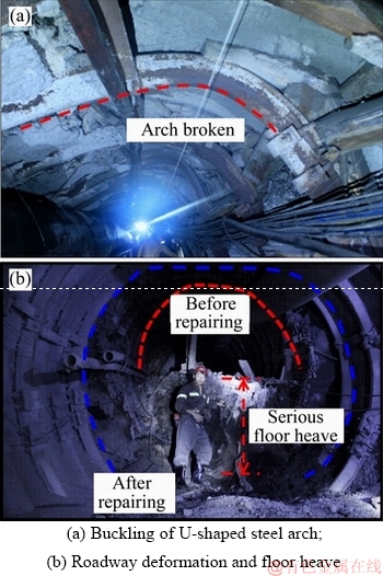
Figure 1 Site investigation of roadway damage in extremely soft rock:
Based on the above background, the authors carried out the full-scale laboratory experiment on CC arch and U36 arch, according with the actual shape and size of the roadway arch. Both the CC and U36 arches have the same steel content in the section. In the experiment, the bearing characteristics and deformation and failure characteristics of the arch are clarified; and the feasibility is studied on replacing the traditional U-shaped steel arches with CC arches. A mechanical calculation model is established for arches with the arbitrary number of sections and non-equal stiffness; the influence of different factors is analyzed on the internal force of the arch; the ultimate bearing capacity of the arch is got according to the buckling strength bearing criterion; and the correctness of theoretical analysis is verified. From all the aspects, research is made on the deformation and damage patterns, and the key damaged positions of the arch. It provides a guide for the design of support scheme on site.
2 Laboratory comparative experiments on CC arches
2.1 Experiment scheme
To compare the mechanical properties and the mechanism of deformation of the CC arch with that of U-shaped steel arch, the circular arch in the field is taken as the research object; a full scale laboratory comparative experiment is conducted on CC and U36 steel arches in the original supporting scheme; and a comparative analysis is made on the deformation and failure modes, the critical damaged positions and the ultimate bearing capacity of the two arches.
The CC arch is 5.2 m in diameter and divided into four sections, each section being connected by a casing. According to the principle of similar steel content of section to U36 steel arch, a circular steel tube is selected with an outer diameter of 159 mm and a wall thickness of 10 mm, presented by CC159��10 below; the cross-sectional area is 4681 mm2 for CC159��10 steel tube and 4570 mm2 for U36 arch; and the difference between the two was 2.37%. The casing size is 194 mm��14 mm and the concrete for filling is C40. According to the stress measurement results of surrounding rock, the same loading method is adopted for both the laboratory and field experiments. The lateral pressure coefficient is 1.5, meaning the horizontal load is 1.5 times of the vertical load. The size of the U36 steel arch is the same as that of CC arch and loading method is also the same for both.
2.2 Experiment methods
Twelve cylinders are used to provide loads to the arch. A specified bias load is achieved on the arch by adjusting the loading force of each cylinder.
Loading method: The method of monotonous pressurization is adopted, the pressures of left and right horizontal cylinders (2#, 3#, 4#, 8#, 9# and 10#) are 1.5 times the pressures of up and down vertical hydraulic cylinders (11#, 1#, 12#, 5#, 6# and 7#) (shown in Figure 2).
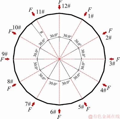
Figure 2 Loading diagram of circular arch
Loading speed rate and pressure holding time: When the load is less than 90% of the ultimate load, the loading speed rate is 10 kN/min and the pressure holding time is 0.5 min/30kN. When the load exceeds 90% of the predicted ultimate load, the loading speed rate is reduced to 5 kN/min, and the pressure is held for 0.5 min every 10 kN.
Loading stop standard: Stop loading, when the entire arch enters the yield state or significant damages occur.
2.3 Experiment phenomenon
2.3.1 Laboratory experiment on CC arches
As shown in Figure 3, the experiment on CC arches lasts for about 1420 s and can be divided into the following four stages:
1) The first stage: Within about 160 s before the experiment, no obvious deformation is observed on the arch and the thrust of each cylinder increases more uniformly.
2) The second stage: As the load continues to increase, the shape of the entire arch is changed from round to oval and both sides are squeezed inward, under the influence of the bias load.
3) The third stage: Up to about 1140 s, the arch load reaches the ultimate load, the arch deformation is sped up, and damages appear on the side.
4) The fourth stage: Up to 1420 s at the end of the experiment, the arch deformation becomes more serious and the most serious damages occur on the both sides.
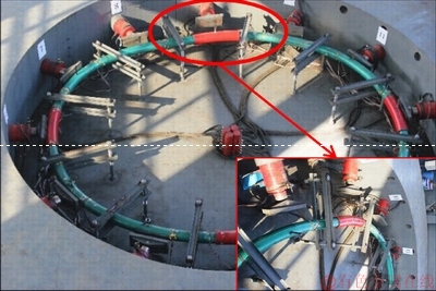
Figure 3 Overall deformation of confined concrete arch
The statistical analysis of the thrust of each cylinder at the end of the experiment shows the ultimate bearing capacity of CC arch is FCC�Cl=2003.2 kN in the laboratory experiment.
2.3.2 U36 steel arch laboratory experiment
As shown in Figure 4, the experiment on U36 steel arches lasts for about 1310 s and can be divided into the following four stages:
1) The first stage: After the experiment begins, the deformation of the arch increases uniformly with the cylinder thrust.
2) The second stage: Up to 510 s, the arch deformation is sped up and the shape of the entire arch is changed from round to oval.
3) The third stage: Up to about 1105 s, the side at the position 3# is suddenly bent inward; buckling damage occurs and the bearing capacity of the entire arch decreases sharply; and the vault between positions 12# and 1# is also seriously bent, and obvious intensity damages occur at the two positions.
4) The fourth stage: Up to 1310 s, at the end of the experiment, the arch deformation becomes more serious and the most serious damages occur on the both sides.
The statistical analysis of the thrust of each cylinder at the end of the experiment shows the ultimate bearing capacity of U36 arch is Fu�Cl=867.5 kN in the laboratory experiment.
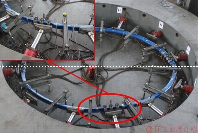
Figure 4 Unstable failure modes of U-shaped arch
2.4 Experiment results analysis
With a similar section steel content, the ultimate bearing capacity of CC arches is 2.31 times higher than that of U36 steel arches, and therefore, CC arch has higher strength bearing capacity.
With the increase of load, the overall shape of both CC and U36 steel arches is changed from circular to oval. However, with the continuous increase of load, the U36 steel arch is suddenly buckled and damaged at the side position and loses its stability; and in contrast, the CC arch still has better planar stability.
The above results show CC arch has the characteristics of high strength and high rigidity, and it is feasible to use CC arch instead of the traditional U-shaped arch.
3 Theoretical analysis on CC arch
At present, there is no theoretical formula for calculating the internal forces and bearing capacity of CC arch with circular cross-section. To design CC arch in the field application, a mechanical calculation model is established for CC arch of circular cross-section with arbitrary section numbers and unequal stiffness; an internal force calculation formula is deduced for any section of the arch; an analysis is made on the influence of different factors on the internal force of the arch; and the ultimate bearing capacity of the arch is got according to the criterion of bending strength. These provide a theoretical guideline for the design of CC arch support.
3.1 Internal force analysis on CC arch
3.1.1 Arch mechanical calculation model
According to the basic parameters and load model of arches in underground engineering, a mechanical calculation model is established for CC arch, as shown in Figure 5.
In Figure 5, the center of the arch is represented by O; radius is represented by R; the lower end is the fixed bearing A point; and the upper end is the sliding bearing B point. OB is the starting line of 0��, the counterclockwise rotation is positive and the rigidity of the arch is EI. The arches are usually connected by flanges or casings. In this paper, the nodes are equivalently processed.
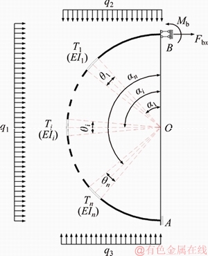
Figure 5 Mechanical calculation model of arch with circular section
Assuming the node is rigid, Ti represents i# node from the starting line 0�� from top to bottom, and its position is represented by the node positioning angle ��i (the position of node center cross-section). The rigidity of the node differs from that of the arch. The influence of the node should be simplified on the overall rigidity to make the calculation more accurate. According to the equivalent rigidity method, the arch node should be replaced by a certain length of a rod with the same cross-section. The rod size is represented by the arch length corresponding to the central angle ��i and the equivalent rigidity of the node is expressed as EI��. The surrounding rock pressure is simplified with the left load as q1, the up load as q2 and the lower load as q3.
In the following mechanical analysis and calculation, the axial force F is positive pressure, and the moment M, as the tension in the arch outside, is positive. The load and the reaction force in the direction shown in Figure 5 are positive.
3.1.2 Internal force calculation and analysis
The mechanical calculation model of the arch is a statically indeterminate structure. The solution can be got by the ��force method�� to release the support restraint at the vault B point and replace it with the extra unidentified forces X1 and X2. Here, X1 represents the horizontal bearing reaction force FBX at point B and X2 represents the restraining moment Mb at point B.
The obtained Eq. (1) shows the equation of force:

 (1)
(1)
According to the virtual work principle, the basic parameters can be got in Eq. (1), according to Eqs. (2) and (3).
 (2)
(2)
In the same way, the expressions of ��22, ��21 and ��12 can be got.

 (3)
(3)
In the same way, the expression of ��2p can be got. With ��1�C��1/2=0, ��n�C��n/2=��, we can get extra unknowns X1 and X2 and then calculate the bending moment and axial force at any section according to Eq. (4).

 (4)
(4)
In Eqs. (1)�C(4), ��ij represents the displacement of the basic structure along the Xi direction under the unit force Xj=1 alone, and ��ip represents the displacement of the basic structure under the load along the Xi direction.  and
and  represent the bending moment and the axial force generated by unit force Xi=1 in any section of the basic structure. Mp and Fp are expressed as the bending moment and the axis force value generated by the load in any section of the basic structure.
3.1.3 Internal force analysis
To verify the correctness of the theoretical analysis, the same parameters of the arches are selected for both the following theoretical calculation and the laboratory experiment. Based on Eq. (4), the internal force of any section of the arch can be calculated under different influence factors, and then the theoretical calculation could be analyzed.
The flexural rigidity of the CC arch can be calculated as EI=3.3��103 kN��m2 and the tensile rigidity EA=1.76��106 kN. The stiffness ratio of the node, the ratio of node stiffness to arch stiffness, is defined as ��=EI��/EI; the side pressure coefficient, ratio of side load to top load is ��=q1/q2, and the upper load q2 is equal to the lower load q3.
1) The impact of load q1 on the internal force of the arch
Setting lateral pressure coefficient ��=1.5 and the node stiffness ratio ��=1.5, a study is made on the relationship curves of internal force P (M, N) with q1, �� under load changes, where �� represents the angle corresponding to the different cross sections of the arch with the values of 0��, 30��, 45��, 60��, 90��, 120��, 150�� and 180�� and values of q1 are 10, 30, 50, 70, 90 and 100 kN/m.
As shown in Figures 6 and 7, the following regular patterns appear on the internal force of the arch with the change of the load q1:
(1) Figures 6(a) and (b) show the bending moment and axial force of each section of the arch are linearly related to the load q1; and the bending moment increases are fastest at 0��, 90�� and 180��, and the axial force has the fastest growth rate at 0�� and 180�� positions.
(2) Figures 6(a) and 7(a) show the bending moment has positive and negative moments. The sign is changed around 45�� and 135�� with the positive moment at the positions of both the vault and the bottom of the arch, and the negative moments at the both sides around 90��.
(3) Figure 6(b) and Figure 7(b) show all the axial force is pressure. The axial force is the smallest in the 90�� position. It gradually increases from 90�� to both sides with a progressive growth rate.
2) Influence of lateral pressure coefficient �� on the internal force of the arch
A study is made on the relationship between the internal force P (M, N) and ��, �� under different lateral pressure coefficient �� by changing the value of q1. We set the node stiffness ratio ��=1.5, keep q2=50 kN/m constant in the study. The values of �� are 0.2, 0.6, 1.0, 1.2, 1.6 and 2.0 in order, and the values of q1 are 10, 30, 50, 70, 90 and 100 kN/m.
Figures 8 and 9 show that the following regular patterns are generated for the internal force of the arch by changing the lateral pressure coefficient ��:

Figure 6 Internal force relationship curves of P�Cq1:
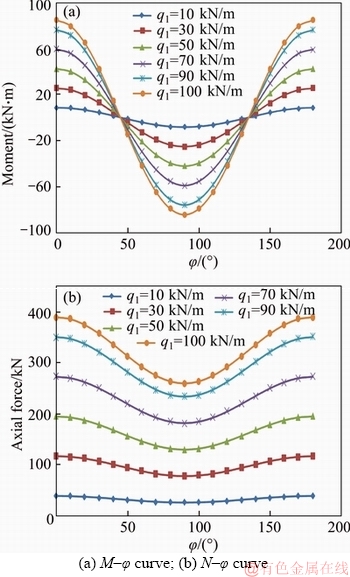
Figure 7 Internal force relationship curves of P�C��:
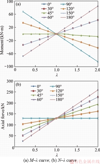
Figure 8 Internal force relationship curves of P�C��:
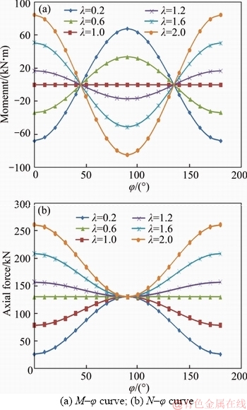
Figure 9 Internal force relationship curves of P�C��:
(1) Figures 8(a) and (b) show the internal force value and the lateral pressure coefficient �� are linearly related. The bending moment increases the fastest and reaches the maximum at 0��, 90�� and 180��. The axial force has the fastest growth rate at 0�� and 180��.
(2) Figure 9(a) show that there are zero moment points at 45�� and 135��. As the lateral pressure coefficient ��=1, there is no bending moment in the arch; as the lateral pressure coefficient ��<1, the vault and the bottom of the arch are stretched inside and stretched outside in 90��; and as lateral pressure coefficient ��>1, the vault and the bottom of the arch are stretched outside and stretched inside in 90��.
(3) Figure 9(b) show the axial force of the arch is always the pressure and the isometric point exists at the position of 90��; as the lateral pressure coefficient ��=1, the axial force of each section of the arch is equal; as the lateral pressure coefficient ��<1, the axial force has the minimum value at the vault and the bottom of the arch, and the maximum axial force is in 90��; and as ��>1, the axial force has the maximum value at the vault and the bottom of the arch, and the minimum axial force is in 90��.
3) Impact of node positioning angle �� on the internal force of the arch
The lateral pressure coefficient is set as ��=1.5, where q2=75 kN/m and q1=50 kN/m; the node stiffness ratio is set as ��=1.5 and two nodes are arranged in 10�� and 20��, and its relative position is kept unchanged. Based on the above mentioned, a study is made on relationship curve between the internal force P (M, N) and ��, as the node moves from 10�� to 70��; and the curve in 0�� is extracted.
As shown in Figures 10 and 11, the following regular patterns are generated on the internal force of the arch by changing the node positioning angle ��:
(1) The influence of the node positioning angle is greater on the arch moment than on the axial force.
(2) The change of the node positioning angle is influenced by the change of the non-equal stiffness node position on the internal force of the arch. The section bending moment will be transferred correspondingly along with the change of the node positioning angle.
3.1.4 Summary
Through summarizing and analyzing, the main influence law of each factor is got on the internal force of arch:
1) The load and lateral pressure coefficients significantly influence the internal force, which is linearly related to the internal force of the arch. The change of node positioning angle has a relatively small influence on internal forces.
2) When the load changes, the bending moment increases most at 0��, 90�� and 180��, and the maximum value of bending moment occurs in these positions. The axial force increases most at 0��and 180��, and the maximum axial force occurs in these positions. The axial force growth rate is gradually increased from 90��to both sides.
3) When the lateral pressure coefficient changes, the bending moment has the fastest growth rate in 0��, 90�� and 180��, and the fastest growth rate of axial force is in 0�� and 180��.
4) As the lateral pressure coefficient ��=1, there is no bending moment in each section, and the axial forces in each section are equal. As ��<1, the vault and bottom of the arch are tensioned inside and the axial force is in its minimum; and the arch is tensioned outside and axial force is maximum in 90��. As ��>1, the situation is the opposite.
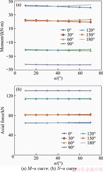
Figure 10 Internal force relationship curves of P�C��:
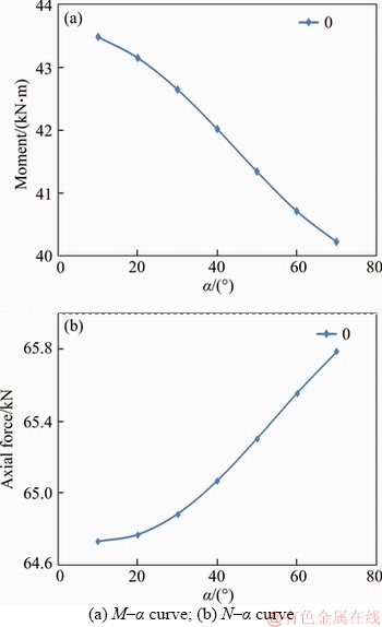
Figure 11 0�� position P�C�� relationship curve:
3.2 CC arch bearing capacity calculation
It is the basis for the design of CC arch to clarify the ultimate bearing capacity of the arch and to grasp the characteristics of the bearing strength.
The support arch in underground engineering mainly bears the joint action of bending moment and axial force load. The ultimate carrying capacity of CC arch can be calculated in the failure of the bending strength, based on the mechanical calculation model of the arch in Figure 5; and the judgment criterion of the damaged bending strength in Ref. [23] is also used in the calculation. The calculation is as shown in Eq. (5).
 (5)
(5)
In Eq. (5), a, b and c are the equation coefficients related to the parameters of the arch section; �� is the steel content in the section (ratio of the steel area to the concrete area); ��m is the equivalent bending moment coefficient; Mu is the pure bending strength of bearing capacity; Nu is the bearing capacity of axial compressive strength; and M and N are the calculated bending moment and axial force of any section.
According to the basic parameters of CC159�� 10 arch, the bearing capacity of arch strength can be calculated according to Eq. (6):
 (6)
(6)
Through Eq. (6), the discrimination curve of N/Nu�CM/Mu strength bearing capacity can be drawn, as shown in Figure 12.
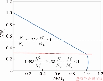
Figure 12 Strength bearing capacity criterion curve of CC159��10 member
The physical meaning of compression bending strength bearing capacity criterion: If the coordinate point of (M/Mu, N/Nu) falls inside the area enclosed by the curve and the positive coordinate axis, the section strength is reliable; and if it falls outside the area, strength damage will occur. This criterion is based on Mu and Nu values obtained and internal force values M and N of arbitrary cross-section.
According to the curve of bearing capacity of CC arch, the calculation procedure is designed for the bearing capacity of the arch; the ultimate bearing capacity of CC159��10 arch is got as Fcc-t=1940.8 kN; and the horizontal and vertical loads are q1=56.0 kN/m and q2=q3=37.3 kN/m. The internal force distribution of the arch is shown in Figure 13.
4 CC arch numerical calculation
The theoretical calculation of the CC159��10 arches is verified to compare with the laboratory mechanical experiment of the full scale arch; and a numerical analysis model, which has the same size with the laboratory experiment arch, is established and a numerical calculation is made.
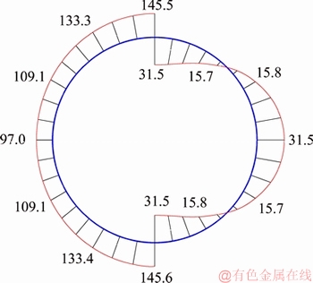
Figure 13 Example of internal force calculation results of circular arch
4.1 Arch numerical calculation model
The ABAQUS finite element software is used to analyze the ultimate bearing capacity and deformation of the arch. The stress�Cstrain relationship model is adopted for the steel and the plastic damage model is used for the concrete. The material parameters are given in the literature [21]. By applying a surface load along the normal direction of the external surface, a loading pattern can be achieved for the specified lateral pressure coefficient. The inner wall of steel pipe and the outer side of concrete are constrained by tie. The parts are assembled into assembly and the mesh generation adopts the mapping mesh method. Meanwhile, three dimensional solid element is adopted for steel tube and core concrete, and C3D8R type is chosen for the elements.
4.2 Experiment results analysis
4.2.1 Comparison of carrying capacity of arches
The calculated ultimate bearing capacity of the arch is Fcc-n=1820.7 kN. Compared with the ultimate bearing capacity of Fcc-1=2003.2 kN in laboratory experiment, the difference rate is ��n�Cl= the difference rate is small, which verifies the correctness of the numerical calculation. In addition, the difference rate of carrying capacity between numerical calculation and theoretical analysis is
  6.19%, and the difference rate between theoretical analysis and laboratory experiment is ��t�Cl=
 the overall difference rate is small.
4.2.2 Analysis and comparison of deformation and failure modes of arches
The numerical calculation of the deformation and stress morphology of the arch in Figure 14, the following analysis and comparison of deformation and failure modes of arches:
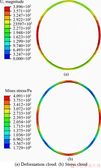
Figure 14 CC159��10 arch deformation and stress cloud:
In the deformation aspect: In the numerical calculation, CC arch is squeezed inward from both sides under the action of the bias load; and the whole shape is changed from circular to oval. This phenomenon is consistent with the deformation of the arch in the laboratory experiment.
In the aspect of internal force distribution: In the numerical calculation, the internal force of the arch is larger at the both sides, the vault and the bottom of the arch. In the theoretical analysis, the bending moment value is the largest on the two sides; and the internal force combination value of the bending moment and the axial force is great.
In deformation and destruction: In the numerical calculation, the deformation and displacement is the largest on the two sides. The strength damage occurs first on the two sides in the laboratory experiment.
The above analysis shows the numerical simulation, the theoretical analysis and the laboratory experiments are consistent on the deformation and failure modes of the arch. The two sides of the arch are the most easily damaged part of the arch, and should be reinforced in the design of the support scheme.
4.2.3 Comparison of internal force mode of arch
Based on the numerical calculation results, the internal force distribution of the arch is got under the ultimate load as shown in Figure 15.
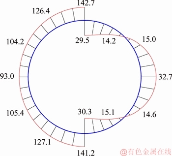
Figure 15 Internal force calculation results of CC159��10 arch in numerical test
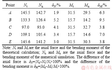
To verify the rationality of theoretical calculation, a comparative analysis is made on the internal force distribution of the theoretical calculation and the numerical calculation. Five points of 0��, 30��, 90��, 120�� and 180�� are selected on one side of the arch and are marked as A, B, C, D and E respectively. The axial force and the bending moment value are extracted for each point in the theoretical calculation and the numerical calculation as shown in Table 1.
Table 1 shows that the maximum difference rate of the axial force of the arch is 5.2% in 30�� and the maximum difference rate of the bending moment is 9.5% in 30��. The difference rate of the axial force and the bending moment of each point are within a reasonable range. The internal forces are more consistent. These prove the correctness of the theoretical calculation.
Table 1 Comparison of results of theoretical calculation and numerical simulation
5 Field applications
U-shaped steel arches have brought the problems of insufficient support strength and frequent repair to Liangjia Coal Mine with the deep soft rock roadways. To solve the problems, the technology of CC arch support is designed and applied on site.
5.1 On site bearing capacity monitoring of U-shaped steel arch
It is the premise of the arch design to understand load bearing capacity. For this purpose, the authors monitored the stress conditions of the traditional U36-type steel arch on site. The semi-circular U36 arch is equipped with seven pressure measuring points uniformly with serial numbers from 1# to 7#. They are mainly to monitor the radial force on the vault, the spandrel and the side (as shown in Figure 16). Due to the force transmission effect of the sleepers and the larger stress area, the phenomenon of stress concentration can be avoided. It can be considered that only seven positions are stressed on the cross section of the arch. The sum of the force on the seven sleepers is the load on the top cross section of the semicircular arch.
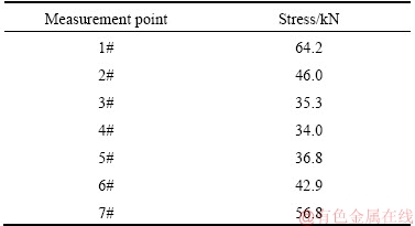
The on-site monitoring is shown in Figure 17. Based on the field monitoring results, the force value of each measuring point (as shown in Table 2) is selected when the arch was stressed most on the 90th day. The sum of the pressure values at each measuring point is 316 kN. The upper and lower cross-section arch are roughly in the same stress state under interaction, so the semi-circular arch pressure value multiplied by 2 is regarded as U36-type steel arch strength bearing capacity Fu-f=632 kN for the on-site test.
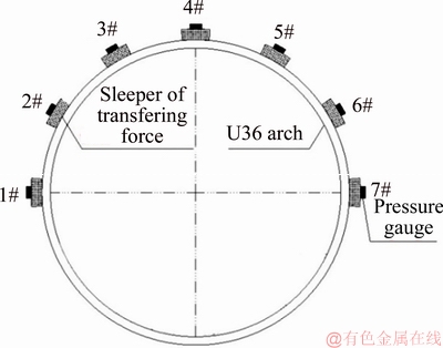
Figure 16 Diagram of U-shaped steel arch monitoring
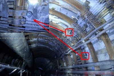
Figure 17 Monitoring of U-shaped steel arch��s bearing capacity
Table 2 Stress of each measurement point
5.2 CC arch support scheme
According to the bearing condition of the arch and the theoretical calculation formula in this paper, the design scheme of CC support is designed. According to the calculation formula of the internal force of the arch (4) and the criterion of bearing capacity of U36 steel arch [21], the theoretical strength carrying capacity is got as Fu-t=961 kN. Compared with the monitoring value of Fu-f=632 kN of the field test, the difference rate of bearing capacity is 34.2%. The main reasons for this are that the on-site geological conditions are complex and the strength bearing capacity of U-shaped steel arch can hardly reach the theoretical calculation value.
The supporting strength of the arch should be fully guaranteed in the design of CC arch support scheme. To this purpose, we assume that the theoretical strength bearing capacity is increased by 100% than U36 arch support bearing capacity Fu-f in the field test; and that means CC arch has double reserve and its theoretical load-bearing capacity should reach 2Fu-f=1264 kN. Meantime, it is taken account that the bearing capacity of U36 arch in the field test is 34.2% lower than the theoretically calculated value and can hardly reach the theoretical bearing capacity. So, here we assume that the theoretical bearing capacity of the CC arch is reduced by 34.2%, and then the theoretical strength of the bearing capacity should reach 1921 kN (1264/65.8%=1921 kN). The theoretical strength bearing capacity of CC159��10 CC arch is Fcc-t=1940.8 kN, which meets the design requirements; and the theoretical strength carrying capacity of CC arch is increased by 202% compared with that of the U36 arch (Fcc-t/Fu-t��100%=202%).
The design scheme adopts CC159��10 Arch, which is divided into 4 sections. The design spacing of the arch, the parameter and form of anchoring and meshing is the same as the original support scheme. Back-wall filling is conducted between the arch and the surrounding rock to ensure arch and surrounding rock uniformly contacted, and to avoid stress concentration. The two sides, which is easy to be broken, is reinforced by the longitudinal connection, and the reinforcing structure and the site implementation plan is shown in Figure 18.
5.3 Support evaluation
After the support experiment is completed, the surrounding rock convergence and deformation are monitored in the roadway. The monitoring results are shown in Figure 19.
According to the monitoring curve of on-site roadway surface, the convergence and deformation speed of the roadway is relatively fast in the first 15 d, and it is slowed down after 30 d and becomes stable after 90 d. The maximum deformation of the right side is 37 mm and the minimum deformation of the left shoulder is 12 mm. This proves that CC support system has a great control effect on the deformation of deep roadway with soft rocks.
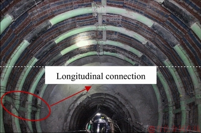
Figure 18 Diagram of confined concrete supporting effect
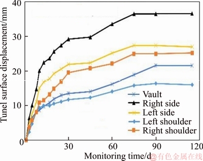
Figure 19 Monitoring of tunnel surface displacement
6 Conclusions
1) To solve the current difficulty of surrounding rock control in underground engineering, the paper puts forward a new high strength supporting technology of CC arch.
2) The mechanical calculation model of CC arch is established. The influence of different factors is analyzed on the internal force of the arch. According to the discriminant formula of the buckling strength of the arch, the calculation program of the bearing capacity is designed and the ultimate bearing capacity of the arch is got. It can provide theoretical guidance for CC arch support design.
3) With similar cross-sectional steel content, the bearing capacity of CC arch is 2.31 times higher than that of the U36 arch. CC arch has higher strength bearing capacity and better plane stability. Under the condition that the lateral pressure coefficient is 1.5, the key damage is on the two sides of the arch that should be reinforced.
4) The design scheme of CC support is put forward and applied in the deep roadway with soft rocks. The application results show that the deformation of surrounding rock can be well controlled with the new technique. This technique can provide a new and effective supporting method for underground engineering with supporting difficulties.
References
[1] YU Wei-jian, WANG Wei-jun, CHEN Xin-yuan, DU Shao-hua. Field investigations of high stress soft surrounding rocks and deformation control [J]. Journal of Rock Mechanics and Geotechnical Engineering, 2015, 7(4): 421�C433. DOI: 10.1016/j.jrmge.2015.03.014.
[2] LIN Peng, LIU Hong-yuan, ZHOU Wei-yuan. Experimental study on failure behavior of deep tunnels under high in-situ stresses [J]. Tunnelling and Underground Space Technology, 2015, 46: 28�C45. DOI: 10.1016/j.tust.2014.10.009.
[3] WU Ai-xiang, HU Kai-jian, HUANG Ming-qing, WANG Yi-ming, WANG Jing-jun. Deformation mechanism and repair support of haulage roadway with weak-fractured surrounding rock [J]. Journal of Central South University: Science and Technology, 2017, 48(8): 2162�C2168. (in Chinese)
[4] WANG Hui, ZHENG Peng-qiang, ZHAO Wen-juan, TIAN Hong-ming. Application of a combined supporting technology with U-shaped steel support and anchor-grouting to surrounding soft rock reinforcement in roadway [J]. Journal of Central South University, 2018, 25(5): 1240�C1250. DOI: 10.1007/s11771-018-3821-9.
[5] MA Zhen-qian, JIANG Yao-dong, DU Wei-sheng, ZUO Yu-jun, KONG De-zhong. Fracture evolution law and control technology of roadways with extra thick soft roof [J]. Engineering Failure Analysis, 2018, 84: 331�C345. DOI: 10.1016/j.engfailanal.2017.08.020.
[6] CHEN Shun-man, WU Ai-xiang, WANG Yi-ming, CHEN Xu, YAN Rong-fu, MA Hao-ji. Study on repair control technology of soft surrounding rock roadway and its application [J]. Engineering Failure Analysis, 2018, 92: 443�C455. DOI:10.1016/j.engfailanal.2018.06.006.
[7] DU Chun-huang, CAO Ping, CHEN Yu, LIU Jie, ZHAO Yan-lin, LIU Jing-shuo. Study on the Stability and Deformation of the Roadway Subjected to High In-Situ Stresses [J]. Geotechnical and Geological Engineering, 2017, 35(4): 1615�C1628. DOI: 10.1007/s10706-017-0197-9.
[8] KANG H P, LIN J, FAN M J. Investigation on support pattern of a coal mine roadway within soft rocks��A case study [J]. International Journal of Coal Geology, 2015, 140: 31�C40. DOI: 10.1016/j.coal.2015.01.003.
[9] ZHAN Ping, MA Nian-jie, JIANG Wei, REN Jian-ju. Combined support technology of large section roadway in high-stress fractured surrounding rock [J]. Procedia Engineering, 2011, 26: 1270�C1278. DOI: 10.1016/j.proeng. 2011.11.2301.
[10] KANG Yong-shui, LIU Quan-sheng, GONG Guang-qing, WANG Huai-chao. Application of a combined support system to the weak floor reinforcement in deep underground coal mine [J]. International Journal of Rock Mechanics and Mining Sciences, 2014, 71: 143�C150. DOI: 10.1016/j.ijrmms. 2014.03.017.
[11] LU Yi-yan, LI Na, LI Shan, LIANG Hong-jun. Experimental investigation of axially loaded steel fiber reinforced high strength concrete-filled steel tube columns [J]. Journal of Central South University, 2015, 22(6): 2287�C2296. DOI: 10.1007/s11771-015-2753-x.
[12] MAHDI N, SAEED F, MORTEZA N, JAVAD J. Experimental study on modulus of elasticity of steel tube-confined concrete stub columns with active and passive confinement [J]. Engineering Structures, 2017, 130: 142�C153. DOI: 10.1016/j.engstruct.2016.10.008.
[13] ELLOBODY E, YOUNG B, LAM D. Behaviour of normal and high strength concrete-filled compact steel tube circular stub columns [J]. Journal of Constructional Steel Research, 2006, 62(7): 706�C715. DOI: 10.1016/j.jcsr.2005.11.002.
[14] HAN Lin-hai, AN Yu-feng. Performance of concrete-encased CFST stub columns under axial compression [J]. Journal of Constructional Steel Research, 2014, 93: 62�C76. DOI: 10.1016/j.jcsr.2013.10.019.
[15] LI Yan, CAI C S, LIU Yang, CHEN Yan-jiang, LIU Jia-feng. Dynamic analysis of a large span specially shaped hybrid girder bridge with concrete-filled steel tube arches [J]. Engineering Structures, 2016, 106: 243�C260. DOI: 10.1016/j.engstruct.2015.10.026.
[16] WANG Zhi-bin, TAO Zhong, HAN Lin-hai, UY B, LAM D, KANG W H. Strength, stiffness and ductility of concrete- filled steel columns underaxial compression [J]. Engineering Structures, 2017, 135,: 209�C221. DOI: 10.1016/j.engstruct. 2016.12.049.
[17] KWON Y B, PARK S W. Resistance of circular concrete- filled tubular sections to combined axial compression and bending [J]. Thin�CWalled Structures, 2017, 111: 93�C102. DOI: 10.1016/j.tws.2016.11.014.
[18] PORTOLS J M, ROMERO M L, BONET J L, FILIPPOU F C. Experimental study of high strength concrete-filled circular tubular columns under eccentric loading [J]. Journal of Constructional Steel Research, 2011, 67(4): 623�C633. DOI: 10.1016/j.jcsr.2010.11.017.
[19] QIN Peng, TAN Yang, XIAO Yan. Low cyclic fatigue performance of concrete-filled steel tube columns [J]. Journal of Central South University, 2015, 22: 4035-4042. DOI: 10.1007/s11771-015-2947-2.
[20] AL-RIFAIE A, JONES S W, WANG Q Y, GUAN Z W. Experimental and numerical study on lateral impact response of concrete filled steel tube columns with end plate connections [J]. International Journal of Impact Engineering, 2018, 121: 20�C34. DOI: 10.1016/j.ijimpeng.2018.07.003.
[21] WANG Q, JIANG B, LI S C, WANG D C, WANG F Q, LI W T, REN Y X, GUO N B, SHAO X. Experimental studies on the mechanical properties and deformation & failure mechanism of U-type confined concrete arch centering [J]. Tunnelling and Underground Space Technology, 2016, 51: 20�C29. DOI: 10.1016/j.tust.2015.10.010.
[22] WANG Qi, JIANG Bei, PAN Rui, LI Shu-cai, HE Man-chao, SUN Hui-bin, QIN Qian, YU Heng-chang, LUAN Yin-cheng. Failure mechanism of surrounding rock with high stress and confined concrete support system [J]. International Journal of Rock Mechanics and Mining Sciences, 2018, 12: 89�C100. DOI: 10.1016/j.ijrmms.2018.01.020.
[23] WANG Qi, SHAO Xing, LI Shu-cai, WANG De-chao, LI Wei-teng, WANG Fu-qi, LIU Wen-jiang, ZHANG Shi-guo. Mechanical properties and failure mechanism of square type confined concrete arch centering [J]. Journal of China Coal Society, 2015, 40(4): 922�C930. DOI: 10.13225/j.cnki.jccs. 2014.0863. (in Chinese)
[24] JIANG Bei. Control mechanism and application of confined concrete for super large section tunnel on weak surrounding rock [D]. Ji��nan: Shandong University, 2016. (in Chinese)
(Edited by HE Yun-bin)
���ĵ���
Լ��������������ѧ���ܷ�����֧����ϵ�ֳ�����
ժҪ����Ե������ҵ��¹��̿������⣬���������Լ����������ǿ֧�����������������з���ȫ�ȳ���ѧ����ϵͳ������Լ�����������ܵ��ƻ����Ƽ���ѧ���ܽ������о���ͬʱ��������Բ�ζ����������������ǵȸնȹ�����ѧ����ģ�ͣ��Ƶ��˹����������㹫ʽ�������˲�ͬ���ضԹ���������Ӱ����ɣ����ѹ��ǿ���б��õ���Լ�����������ܳ����������㹫ʽ��������۷�������ֵ��������������Լ�����������ܵļ��������������ֲ������˶Աȷ������о����������1)Լ�����������ܱȴ�ͳU�ֹ���ǿ�����2.31�����Ҿ��и��õ��ȶ��ԣ�2)���ܹؼ��ƻ���λΪ����ﲿ��3)���۷�������ֵ�����Լ����������ڹ��ܵ������ֲ������������ͱ����ƻ���̬�ȷ�����нϺõ�һ���ԣ���֤�����ۼ������ȷ�ԡ��������о��Ļ����ϣ���չ������ú��Լ��������֧���ֳ����飬�봫ͳU�ֹ���֧����ȣ�����֧����Ч������Χ�ұ��Ρ��о��ɹ���Ϊ���¹���Լ����������ǿ֧������ṩ���ݡ�
�ؼ��ʣ�Լ�����������ܣ�ȫ�ȳ��������飻���۷�������ֵ���飻�ֳ�Ӧ��
Foundation item: Projects(51674154, 51704125, 51874188) supported by the National Natural Science Foundation of China; Projects(2017T100116, 2017T100491, 2016M590150, 2016M602144) supported by the China Postdoctoral Science Foundation; Projects(2017GGX30101, 2018GGX109001, ZR2017QEE013) supported by the Natural Science Foundation of Shandong Province, China; Project(SKLCRSM18KF012) supported by the State Key Laboratory of Coal Resources and Safe Mining, China; Project(2018WLJH76) supported by the Young Scholars Program of Shandong University, China
Received date: 2018-04-02; Accepted date: 2018-10-30
Corresponding author: JIANG Bei, PhD, Associate Professor; E-mail: jiangbei519@163.com; ORCID: 0000-0002-3323-5557
Abstract: Soft rock control is a big challenge in underground engineering. As for this problem, a high-strength support technique of confined concrete (CC) arches is proposed and studied in this paper. Based on full-scale mechanical test system of arch, research is made on the failure mechanism and mechanical properties of CC arch. Then, a mechanical calculation model of circular section is established for the arches with arbitrary section and unequal rigidity; a calculation formula is deduced for the internal force of the arch; an analysis is made on the influence of different factors on the internal force of the arch; and a calculation formula is got for the bearing capacity of CC arch through the strength criterion of bearing capacity. With numerical calculation and laboratory experiment, the ultimate bearing capacity and internal force distribution is analyzed for CC arches. The research results show that: 1) CC arch is 2.31 times higher in strength than the U-shaped steel arch and has better stability; 2) The key damage position of the arch is the two sides; 3) Theoretical analysis, numerical calculation and laboratory experiment have good consistency in the internal force distribution, bearing capacity, and deformation and failure modes of the arch. All of that verifies the correctness of the theoretical calculation. Based on the above results, a field experiment is carried out in Liangjia Mine. Compared with the U-shaped steel arch support, CC arch support is more effective in surrounding rock deformation control. The research results can provide a basis for the design of CC arch support in underground engineering.
