
J. Cent. South Univ. (2012) 19: 517-521
DOI: 10.1007/s11771-012-1034-1![]()
Relationship between rectification moment and angle of shield based on numerical simulation
SUN Wei(��ΰ)1, YUE Ming(����)2, WEI Jian(κ��)1
1. School of Mechanical Engineering, Dalian University of Technology, Dalian 116028, China;
2. School of Automotive Engineering, Dalian University of Technology, Dalian 116028, China
? Central South University Press and Springer-Verlag Berlin Heidelberg 2012
Abstract:
The finite element method is used to simulate the rectification process of shield machine, to study the relationship between rectification moment and angle and to explore the influence laws of different soil parameters and buried depth on rectification moment. It is hoped that the reference value of rectification moment can be offered to operator, and theoretical foundation can be laid for future automatic rectification technology. The results show that the rectification moment and angle generally exhibit good linear behavior in clay layers with different soil parameters or buried depths, and then the concept of rectification coefficient, that is, the ratio of rectification angle to rectification moment, is proposed; different soil parameters and buried depths have different influences on rectification coefficient, in which elastic modulus has great influence but others have little influences; the simulations of rectification process are preformed in clay layers with different elastic modulus, and fitting results show that elastic modulus and rectification coefficient present the quadratic function relation.
Key words:
finite element method; rectification moment; rectification angle; elastic modulus��
1 Introduction
At present, the rectification control method of shield machine depends on measured data. Firstly, deflection angle is determined according to measured data of pose. When it exceeds allowable value, the machine alarms and the driver operates reversely to make the shield machine return to design axis [1]. Since the complexity of working condition causes many interference factors during construction, this kind of rectification control method which relies solely on construction experience will lead to great rectification error. Analyzing the action law of rectification loads deeply and studying the mechanical behavior characteristic of rectification have theoretical and practical significance in both present construction operation and future automatic rectification technology.
The loads of shield machine during rectification process present heavy load, dynamic load and offset load characteristics, which are different from that during forward tunneling process. Together with strong nonlinear constitutive relation of soil, it is unpractical to establish precise mechanical model [2-3]. Additionally, the electrohydraulic thrust cylinders which are responsible for regulating attitudes are controlled by group. The difference of thrust forces of the hydraulic actuators would cause the direct rectification moment with respect to the shieldtail centers. Therefore, this rectification moment could be defined to simplify the analysis process according to the practical tunneling. Based on these viewpoints, the finite element method is used to simulate the rectification process of shield machine, to study the relationship between rectification moment and angle, and to explore the influence laws of different soil parameters or buried depths on the rectification moment.
Finite element analysis method can express complex non-linear process by constructing discrete form mathematical model, so that the simulation process is basically consistent with the actual physical process. This method has become a practical technology, and has been applied in many fields [4]. The applications of finite element method in shield tunneling are as follows: LEE and ROWE analyzed the finite element modeling of the three-dimensional ground deformations due to tunneling in soft cohesive soils [5-6]; EXADAKTYLOS and STAVROPOULOU explored a closed-form elastic solution for stresses and displacements around tunnels by finite element method [7]; BRASSING and BEZUIJEN modeled the grouting process around a tunnel lining in a geotechnical centrifuge [8]; ZHANG et al researched surface settlement and surface deformation of shield tunnel by finite element method [9]; SUN analyzed various impact factors and the law of surface settlement by three-dimensional finite element method, and furthermore explored the construction deformation of Shanghai subway overlap shield tunnel by three- dimensional elastic-plastic finite element method [10]; WANG and SHI analyzed the force condition of tunnel segment [11]; XU researched the influencing factors of transverse seismic response of shield tunnel [12].
In this work, the three-dimensional finite element numerical model of shield machine is established to simulate the shield rectification process and then analyze the relationship between shield force and behavior of the shield, that is, the relationship between rectification moment and rectification angle. The pressure distribution of the cylinder can be determined by investigating the relationship between rectification moment and rectification angle and the influence laws of different soil parameters and buried depths on the above-mentioned relationship. It is hoped that theoretical foundation can be provided for automatic rectification technology of the shield machine. Note that the rectification in vertical plane is analyzed in this work, since the vertical rectification process influenced by the weight of shield machine is more difficult than that in horizontal plane. However, the simulation methods are also suitable to analyze the horizontal rectification process.
2 Finite element modeling
2.1 Soil model selection
Since the physical properties of soil are very complex, it is difficult to generalize all properties by a single model. Even if it exists, there will be quite some parameters in the model, which cannot be measured one by one. So, according to concrete region, project and soil, a kind of model, which can best present the main properties of soil and whose parameters can be measured more simply, should be adopted. D-P model is intended to be used in this work, because it can better present properties of soil and its parameters are relatively less which can also be easily obtained from conventional geological report [13].
D-P model uses generalized von Mises yield criterion, and the expression is as follows:
![]() (1)
(1)
where F is the yield function; I1 and J2 are the first and second invariant of stress tensor; K is the bulk modulus.
The relational expression of stress-strain can be obtained according to D-P model:
![]() (2)
(2)
 (3)
(3)
where ��ij is the total strain; ��ij is the total stress; G is the shear modulus; ��kk is the volumetric strain.
The parameters �� and K in D-P model are material constants of D-P criterion, which can be expressed as the function expression of cohesion C and internal friction angle �� as follows:
![]() (4)
(4)
![]() (5)
(5)
2.2 Premise and hypothesis
According to the practical situation, some hypotheses should be introduced in simulation circumstances:
1) The variables, which are closely related to construction and are difficult to quantify, such as the gap of shield tail, the degree of grouting, the degree and range of tunnel soil being disturbed, will be generalized as equivalent circle zone which is homogeneous and thickness-equivalent [14].
2) Relative sliding may happen between shield machine and the peripheral soil during tunneling. So, shield/soil interface is assumed to be interface element and the relative displacement of contact pair is used to simulate the sliding between shield machine and the peripheral soil.
3) The segment is considered as a homogeneous ring and the shield machine, together with the cutter head, is considered as homogeneous cylinder.
4) The materials of segment and equivalent circle zone are treated as elastic materials; the soil layer in which shield machine tunnels is regarded as single soil layer; the torque is applied to shieldtail to simulate the rectification moment.
2.3 Finite element model
According to a practical shield machine, some parameters are chosen as follows: the length of shield machine is 7.57 m and the external diameter is 6.25 m; the segment is 1.2 m in width and 0.3 m in thickness; the mass of shield is calculated to be 370 t. Solid95 element is applied for the simulation of soil and Solid45 for the segment and equivalent circle zone. Moreover, the boundary constraint conditions during calculating are as follows: the ground surface is free boundary; all nodes in left and right sides are subjected to the displacement constraints in the x direction; all nodes in front and back are subjected to the displacement constraints in the z direction; all nodes in bottom surface are subjected to the displacement constraints in the y direction.
Considering that the soil mass is an infinite body and the range of soil stress redistribution after tunnel excavating is 3-5 times of tunnel radius, three- dimensional finite element model of soil body has a length of 40 m, a width of 40 m and a height of 40 m. The buried depth of shield machine is 16.875 m. There are five segments spliced with a total length of 6 m. The model is established, as shown in Fig. 1.
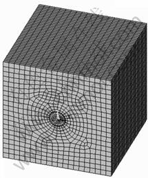
Fig. 1 Three-dimensional finite element model
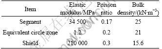
In this case, the simulation is based on the assumption that the shield machine tunnels in a single soil layer. There will be ten difficult simulation environments, as listed in Table 1. These ten difficult simulation environments can be divided into three groups in order to analyze the influences of soil bulk density, buried depth and elastic modulus on rectification moment. Other material parameters used in this simulation are listed in Table 2.
Table 1 Simulation environment parameters
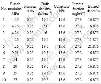
Table 2 Other material parameters
3 Analyses of simulation results
Considering every proposed simulation environment, ten difficult torques (6-60 MN��m) are selected for the simulation analysis.
3.1 Influences of soil bulk density on rectification moment
According to the simulation environments of the first group (No. 1, No. 2 and No. 3), it can be seen that all the parameters are the same except the soil bulk density. It can be seen from simulation results that for difficult soil layers, the rectification moment and angle generally exhibit good linear behavior. Linear fitting is applied to simulation results with the confidence of 95% (analysis processes of other groups are similar to this one). Based on this, the concept of rectification coefficient k is proposed in this work, that is, the ratio of rectification angle to rectification moment. Let T be the rectification moment and �� be the anticipant rectification angle, and the rectification coefficient can be defined as
![]() (6)
(6)
The fitting results of the first group are compared, as shown in Fig. 2.

Fig. 2 Comparison of fitting results of first group (�� is soil bulk density)
It can be seen from Fig. 2 that the slope of fitting straight line decreases continuously along with the increase of soil bulk, which means that the rectification angle under the same rectification moment decreases continuously, but the decrease range is very small. The value range of soil bulk density is generally between 16 kN/m3 and 23 kN/m3. Within the value range mentioned above, the change range of rectification coefficient is about 0.065% which is very small.
3.2 Influences of buried depth on rectification moment
According to the simulation environments of the second group (No. 1, No. 4 and No. 5), one will find that all the parameters are the same except the buried depth. Comparison of fitting results of the second group is shown in Fig. 3.
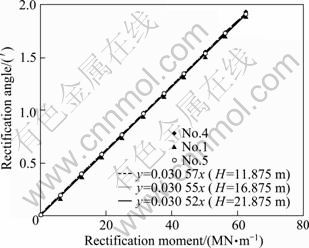
Fig. 3 Comparison of fitting results of second group (H is buried depth)
It can be seen from Fig. 3 that the slope of fitting straight line decreases continuously along with the increase of buried depth, which means that the rectification angle under the same rectification moment decreases continuously, but the decrease range is very small. As the buried depth increases by 84%, rectification coefficient just decreases by 0.16%.
3.3 Influences of elastic modulus on rectification moment
According to the simulation environments of the third group (No. 1, No. 6-No. 10), one will find that all the parameters are the same except the elastic modulus. Comparison of fitting results of the third group is shown in Fig. 4.
It can be seen from Fig. 4 that the slope of fitting straight line decreases continuously along with the increase of elastic modulus, which means that the rectification angle under the same rectification moment decreases continuously. The change range of elastic modulus is relatively wider and elastic modulus has a greater influence on rectification coefficient.
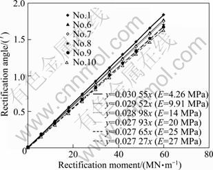
Fig. 4 Comparison of fitting results of third group (E is elastic modulus)
4 Rectification mechanism model characterized by elastic modulus
It can be concluded that elastic modulus E has greater influence on rectification coefficient but other parameters have little influences. Without considering the little influences of other parameters, elastic modulus E can be used to express the rectification coefficient k. So the relationship between rectification moment and angle can be determined by a given elastic modulus E.
The relation curve between elastic modulus E and rectification coefficient k can be obtained by curve fitting, as shown in Fig. 5.
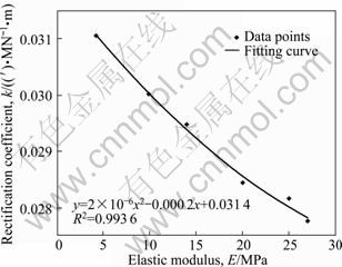
Fig. 5 Relation curve between elastic modulus and rectification coefficient
It can be seen from Fig. 5 that elastic modulus and rectification coefficient present the quadratic function relation. The fitting result of relation curve is as follows:
![]() (7)
(7)
The goodness of fit test reaches 0.993 6 which reflects the fitting accuracy is acceptable. According to Eq. (7), the rectification coefficient k can be determined by elastic modulus E. Then, the rectification moment T can be obtained from rectification coefficient calculated above and elastic modulus measured in advance by the following evaluation equation:
![]() (8)
(8)
It is a reference value for present rectification operation by which the theoretical foundation is established for the future automatic rectification technology.
5 Conclusions
1) The rectification moment and angle generally exhibit good linear behavior in clay layers with different soil parameters and buried depths. Based on this, the concept of rectification coefficient is proposed.
2) Different soil parameters and buried depths have different influences on rectification coefficient, in which elastic modulus has great influence but others have little influences. Without considering the little influences of other parameters, elastic modulus and rectification coefficient present the quadratic function relation.
3) Since there is a distinction of active earth pressure and passive earth pressure, the elastic modulus of soil on two sides of shield machine should be different. The rectification angle is very small, so the nuance above is neglected. In the future work, the influences of active earth pressure and passive earth pressure will be fully considered and more accurate simulation will be carried out to explore the relationship between the rectification moment and rectification angle.
References
[1] ZHENG Xiang-hong. On the deviation and control of shield attitude [J]. West-China Exploration Engineering, 2006(1): 162-163. (in Chinese)
[2] WU Li, QU Fu-zheng. Discrete element simulation of mechanical characteristic of conditioned sands in earth pressure balance shield tunneling [J]. Journal of Central South University of Technology, 2009, 16: 1028-1033.
[3] YUE Ming, WEI Jian, SUN Wei, GUO Zheng-gang. Dynamic mechanism and key rectification techniques of shield machine in the vertical plane [C]// Intelligent Robotics and Applications. Heidelberg: Springer, 2009: 412-422.
[4] ZHENG Yi, ZHAO Guo-xiong, SUN Sheng. High speed objects impaction research by finite element method [J]. Journal of Mechanical Strength, 2003, 25(1): 36-38. (in Chinese)
[5] LEE K M, ROWE R K. Finite element modeling of the three-dimensional ground deformations due to tunneling in son cohesive soils:
[6] LEE K M, ROWE R K. An analysis of three-dimensional ground movements: The thunder bay tunnel [J]. Canadian Geotechnical Journal, 1991, 28(1): 25-41.
[7] EXADAKTYLOS G E, STAVROPOULOU M C. A closed-form elastic solution for stresses and displacements around tunnels [J]. International Journal of Rock Mechanics & Mining Sciences, 2002, 39: 102-110.
[8] BRASSING H E, BEZUIJEN A. Modelling the grouting process around a tunnel lining in a geotechnical centrifuge [C]// Proceeding of the 15th International Conference on Soil Mechanics and Geotechnical Engineering. Istanbul, Turkey: 2001: 1455-1458.
[9] ZHANG Hong-zhou, GE Ke-shui, ZHAI Jian-hua. Research on ANSYS method for shield-driven tunnel earth��s surface settlement pre-estimating [J]. Liaoning Communication Science and Technology, 2006(10): 62-64. (in Chinese)
[10] SUN Jun. Soil disturbance and the environmental stability control in urban areas under shield tunneling [C]// 2nd China-Japan Joint Symposium on Recent Development of Theory and Practice in Geotechnology. Hong Kong, China: 1999: 9-10.
[11] WANG Zhong-shun, SHI Ye-fei. Finite element analysis of the shield tunnel segment [J]. Journal of Zhejiang Vocational and Technical Institute of Transportation, 2005, 6(3): 43-46. (in Chinese)
[12] XU Li-juan. Study on influencing factors of transverse seismic response of shield tunnel [D]. Suzhou: Suzhou University of Science and Technology, 2008. (in Chinese)
[13] DRUCKER D C. Definition of stable inelastic material [J]. Journal of Applied Mechanics-Transactions of the ASME, 1959, 26(1): 101-106.
[14] ZHANG Hong-zhou, ZHANG Jin-wei, ZHAI Jian-hua. ANSYS method for deduction of parameters of equivalent circular zone of shield tunnel [J]. Tunnel Construction, 2006, 26(5): 8-10. (in Chinese)
(Edited by YANG Bing)
Foundation item: Project(2007CB714006) supported by the National Basic Research Program of China
Received date: 2010-09-21; Accepted date: 2011-01-10
Corresponding author: YUE Ming, PhD; Tel: +86-411-84707435; E-mail: yueming@dlut.edu.cn
Abstract: The finite element method is used to simulate the rectification process of shield machine, to study the relationship between rectification moment and angle and to explore the influence laws of different soil parameters and buried depth on rectification moment. It is hoped that the reference value of rectification moment can be offered to operator, and theoretical foundation can be laid for future automatic rectification technology. The results show that the rectification moment and angle generally exhibit good linear behavior in clay layers with different soil parameters or buried depths, and then the concept of rectification coefficient, that is, the ratio of rectification angle to rectification moment, is proposed; different soil parameters and buried depths have different influences on rectification coefficient, in which elastic modulus has great influence but others have little influences; the simulations of rectification process are preformed in clay layers with different elastic modulus, and fitting results show that elastic modulus and rectification coefficient present the quadratic function relation.
