

J. Cent. South Univ. (2020) 27: 2763-2775
DOI: https://doi.org/10.1007/s11771-020-4497-5

Crashworthiness design and experimental validation of a novel collision post structure for subway cab cars
XING Jie(�Ͻ�)1, 2, XU Ping(��ƽ)1, 2, ZHAO Hui(�Ի�)1, 2,
YAO Shu-guang(Ҧ���)1, 2, WANG Qian-xuan(��ǰѡ)3, LI Ben-huai(���)1, 2
1. Key Laboratory of Traffic Safety on Track, Ministry of Education, Central South University,Changsha 410083, China;
2. Joint International Research Laboratory of Key Technology for Rail Traffic Safety,Changsha 410083, China;
3. School of Railway Tracks and Transportation, Wuyi University, Jiangmen 529020, China;
 Central South University Press and Springer-Verlag GmbH Germany, part of Springer Nature 2020
Abstract:
This paper proposes a novel collision post structure designed to improve the crashworthiness of subway cab cars. The structure provides two innovative features: 1) a simpler connection between the post and the car roof, which gives a more reasonable load transfer path to reduce the stress concentration at the joint; and 2) a stiffness induction design that provides an ideal deformation model to protect the safe space of the cab cars. The novel collision post structure was evaluated with finite element analysis, and a prototype cab car was mechanically tested. The results demonstrate that the deformation response was stable and agreed well with the expected ideal mode. The maximum load was 874.17 kN and the responses remained well above the elastic design load of 334 kN as required by the design specification. In addition, there was no significant tearing failure during the whole test process. Therefore, the novel collision post structure proposed has met the requirements specified in new standard to improve the crashworthiness of subway cab cars. Finally, the energy absorption efficiency and light weight design highlights were also summarized and discussed.
Key words:
collision post structure; subway cab cars; crashworthiness; quasi-static test��
Cite this article as:
XING Jie, XU Ping, ZHAO Hui, YAO Shu-guang, WANG Qian-xuan, LI Ben-huai. Crashworthiness design and experimental validation of a novel collision post structure for subway cab cars [J]. Journal of Central South University, 2020, 27(9): 2763-2775.
DOI:https://dx.doi.org/https://doi.org/10.1007/s11771-020-4497-51 Introduction
The issue of crashworthiness requirements for subway cab cars has been a topic of discussion for some time. Cab cars are passenger-carrying vehicles located at the very end of the subway train. The operator is positioned at the end of the cab car where he or she can have a good visibility of the track. However, the proximity of the operator to the very end of the car puts him or her at greater risk in the event of a collision condition.
Generally, crashworthiness research focuses on the scenario that a leading cab car hits another train head on. In this scenario, the underframe and the superstructure of the cab car are loaded. The energy-absorbing component installed on the underframe dissipates the kinetic energy through various forms plastic deformation. Many literatures have reported on the design and structural optimization of the underframe energy-absorbing structures [1-10]. After continuous research and development, the passive safety performance of the cab car under this collision condition has been greatly improved. But there are some special circumstances that make the energy absorbing structure not working properly [11-14]. On June 18, 1998, a train collided with a highway truck at a grade crossing in Portage, USA. The highway truck consisted of a tractor with two trailers. The trailers were loaded with coils of sheet steel. The train collided with the second trailer, and during the impact, a coil of steel broke free and punctured the end of the car. The steel coil rolled down half the length of the car and killed three people, as shown in Figure 1 [15].
In this extreme collision scenario, a leading cab car hits an object at a grade crossing in such a manner that the superstructure is loaded, but the underframe is not. Since the underframe of the cab car provides the greatest strength to protect passengers, this scenario can be dangerous for operators and passengers if the end frame is breached by the object. Hence, the design of cab car end structure should include collision post structure that provides protection against intrusion.
Since the mid 1990��s, there has been research about design layout development, finite element analysis and component testing of the end frame structures to increase the strength of cab cars [16, 17]. The results have demonstrated that a substantial improvement is possible without incurring an undue penalty in weight and cost.
From 2003 to 2009, based on the higher strength requirements that were given in the American Public Transportation Association (APTA) S-034 [18], a series of studies were carried out, including cab car end structural design and fabrication [19, 20], heavy object impact [21-25], train-to-train impact [26], test sled impact [27, 28] and quasi-static crush [29]. These investigations mainly focused on the state-of-the-art (SOA) design at that time. As indicated in Figure 2, the collision post crushes and severe tears appear on the post where it is attached to the underframe. Due to the failure and tearing, the safe space of the driver��s cab is invaded. In order to optimize the design scheme, increasing the strength and stiffness of the collision column can effectively avoid connection failure, but at the same time, it will increase the impact force and cause excessive acceleration of the carbody.
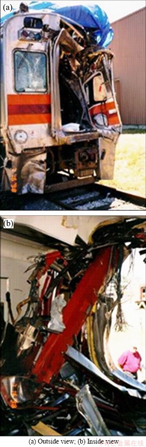
Figure 1 Cab car destroyed in grade crossing collision in Portage, USA:
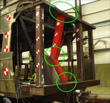
Figure 2 Collision post crushed after quasi-static test [29]
Therefore, this paper provides a novel collision post design which can satisfy the two opposing design requirements mentioned above and improve the crashworthiness of cab cars. The remainder of this paper is structured as follows. We firstly provide the design specification of the collision post in Section 2. In Section 3, the design process is detailed described, including the theoretical analysis and numerical simulation. The prototype evaluation experiment and its results are presented and discussed in Section 4. Finally, the key conclusions and highlights of this paper are summarized in Section 5.
2 Design specification
The objective of this paper is that the crash performance of the collision post structure can meet the requirements while reducing weight and cost. The relevant detailed requirements in the ASME RT-2-2014 standard are shown in Table 1 [30].
According to the above evaluation criteria and other design requirements, the newly designed collision post should:
1) Be strong enough with a critical buckling load greater than the elastic design load (334 kN);
2) Be flexible enough with the post deflection of the center great than 1/3 of its full depth (72 mm);
3) Avoid the stress concentration and local tearing condition at the joint location.
3 Design method and process
3.1 Theoretical derivation
In general, the collision post structure is designed as a hollow column with a rectangular section. It is connected to the car body through roof and underframe, as shown in Figure 3(a). When the collision post bears the load specified by the standard, the mechanical model can be considered as a beam structure with fixed constraint at both ends, as displayed in Figure 3(b).
In order to obtain the bending internal force and corresponding deformation of the beam structure, the external constraints on points A and B need to be solved first. According to the Castigliano��s theorem: if there are n generalized forces F1, F2, ��, Fn acting on an elastic structure, and the displacement along each generalized force direction is ��1, ��2, ��, ��n, the partial derivative of the strain energy U with the general displacement ��i is equal to the corresponding general force Fi, as illustrated in Eq. (1).
 (1)
(1)
Assuming that the elasticity modulus is E and the static moment is I, the bending moment of the beam structure can be expressed as:
 (2)
(2)
If the influence of axial deformation is ignored, the deformation energy of the beam can be expressed as:
 (3)
(3)
The deflection and rotation angle of point B can be expressed as:

 (4)
(4)

 (5)
(5)
According to the boundary conditions fB=0, ��B=0 and equilibrium equation:
Table 1 Elastic-plastic structural load requirements

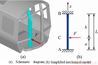
Figure 3 Schematic diagram and simplified mechanical model of collision post:
 (6)
(6)
Simultaneous Eqs. (4)-(6), the results can be solved as:
 ,
,
 (7)
(7)
Substituting Eq. (7) into Eq. (2), the bending moment distribution of the beam structure can be solved and is shown in Figure 4. And at the same time, we can get:
Because aC|<|MB|< |MA|. Therefore, with the continuous increase of force F, the failure process of beam structure can be divided into three phases, as displayed in Figure 5.
Phase 1: As the load increases gradually, the first plastic hinge appears at Point A with the maximum bending moment. At this time, the beam structure has not loosed its bearing capacity;
Phase 2: As the load increases further, the second plastic hinge appears at Point B. But the load can still be increased;
Phase 3: When the third plastic hinge appears at Point C, beam structure has reached the limit state and cannot withstand higher load. If the loading continues to the specified displacement, the maximum longitudinal displacement will be obtained near Point C.
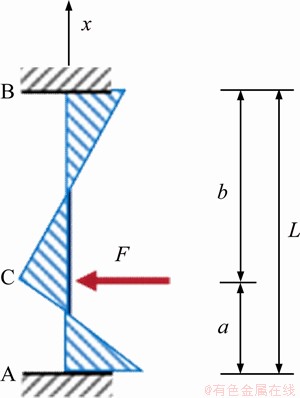
Figure 4 Bending moment distribution of beam structure
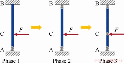
Figure 5 Failure process of beam structure under continuous loading condition
In terms of the crashworthiness of the collision post structure, when the displacement at middle height of the post meets the standard requirements, Point C will have more deformation, which is obviously not conducive to the protection of the safe space of the cab car. Therefore, the bending resistance capacity of the collision post should be redistributed. The plastic hinge should be induced and generated at middle-height of the post. Therefore, the ultimate maximum displacement occurs at the ideal position, as illustrated in Figure 6.
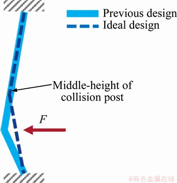
Figure 6 Deformation comparison of previous and ideal designs
3.2 Innovative design details
To improve the crashworthiness and reduce the loss of safe space in the cab cars, the novel collision post structures have two innovative improvements, as shown in Figure 7.
Firstly, the stiffness induction design of the collision post is carried out. A U-shape reinforce diaphragm is added inside the hollow post, as displayed in Figure 7(a). The novel design enhances the bending resistance of the lower half of the post, and induces the plastic hinge generated at the middle-height position. As a result, the ideal deformation condition mentioned in the previous section is obtained.
Then, the connection between the top of the post and its attached structures has been modified. The original anti-telescoping (AT) plate structure is cancelled and the top of the post is directly connected to the roof. This design decreases the load transfer path from the top of the post to the roof, which is more reasonable. Based on this, the stress concentration at the joint can be reduced as well.
3.3 Numerical simulation
In order to verify whether the design meets the requirements, the simulation of the elastic-plastic loading condition is set up using explicit dynamic analyses with LS-DYNA. The model used for the analysis is displayed in Figure 8. The fixed constraint is applied at the rear of the carbody, the load is applied using a rigid ram at 450 mm above the top of the end sill. In order to simulate the elastic-plastic behavior of materials in the loading process, ��MAT_PLASTIC_KINEMATIC�� material type is selected. The material properties defined in finite element model are shown in Table 2. The source data are obtained from quasi-static tensile tests. As an example, the test condition and specimens fractured after test of ASTM A588-A material are displayed in Figure 9. Among them, the collision post structure is made of ASTM A588-A material, and the U-shape diaphragms are made of AISI 301LN-1/4 H material. In order to simulate the possible tearing conditions, the maximum principal strain failure criterion was added to the material model.
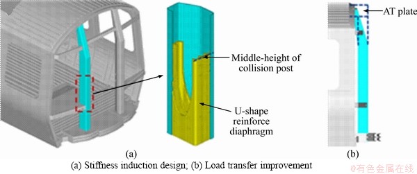
Figure 7 Innovative details of newly designed collision post structures:
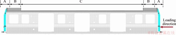
Figure 8 Finite element model for elastic-plastic loading condition
Table 2 Material properties defined in finite element model
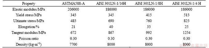
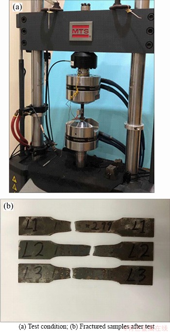
Figure 9 Material tests of ASTM A588-A material:
As illustrated in Figure 10, the load is applied rapidly but using a smooth curve at a rate that would not introduce significant dynamic effects in the structure. The ram is initially adjacent to the collision post outer face and is pushed inward by 100 mm over approximately 170 ms. After reaching a peak inward displacement the direction of the ram is smoothly reversed relaxing the applied load. The magnitude of the peak displacement is determined in preliminary analyses where the magnitude of elastic spring back and collision post crush deformations under the loading ram are evaluated. The displacement level is found to be sufficient to produce the required residual permanent displacement levels when the load is removed.
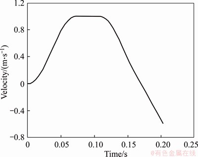
Figure 10 Loading velocity of rigid ram
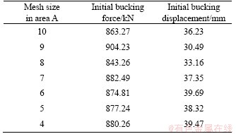
The mesh size is critical to the accuracy and computing efficiency of the finite element simulation, therefore a mesh sensitivity analysis is performed. Considering the whole structure of the carbody is relatively large and the main plastic deformation occurs concentrated in the front-end area, different mesh sizes are used for different parts of the entire model. In order to determine the optimal mesh density in area A, several pre-test simulations are conducted to select the optimal mesh size. As displayed in Table 3, when the element size is less than 7 mm, the calculation results have tended to be stable. Therefore, the mesh size of this area is determined to be 6 mm. As for area C, no obvious plastic deformation occurs in this area during the simulation, so the mesh size is chosen to be 20 mm. In terms of area B, the mesh size is uniformly transitioned from 6 to 20 mm, thereby connecting the elements of areas A and C.
Table 3 Sensitivity analysis of mesh size in area
According to the numerical prediction shown in Figure 11(a), the collision post deformation is well induced and the plastic hinge generates at the middle-height of post. The displacements at specified locations are 200.21 and 156.03 mm when initially unloads and finally unloads, respectively. The results are far beyond the design requirements of 72 mm. The force-displacement curve is displayed in Figure 11(b). The maximum load is 874.81 kN which occurs when displacement is 39.69 mm. Then, the load drops slightly and starts to oscillate, but always remains above the elastic design level of 334 kN. In addition, the collision post and its attached connection structure do not tear or fail during the whole analysis process. Therefore, the novel collision post structure can meet all the design criteria.
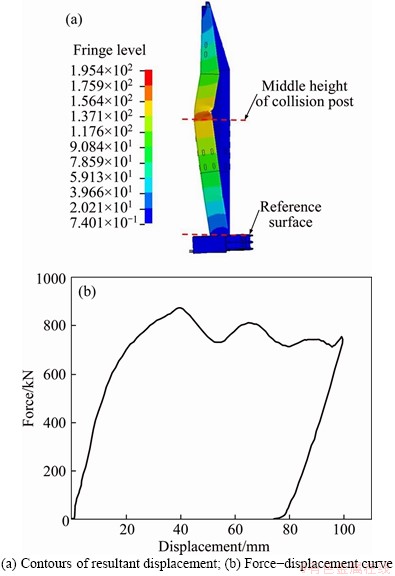
Figure 11 Numerical results of newly designed collision post under elastic-plastic loading condition:
4 Prototype experiment
4.1 Experimental set-up
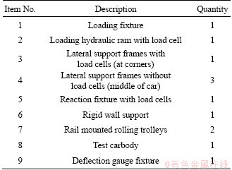
The test configuration for the quasi-static test is illustrated in Figure 12. Component descriptions for each identified item are contained in Table 4. The setup includes a prototype carbody on rails, longitudinally supported at one end by a rigid wall and loaded on the other end through a heavy duty loading fixture. The carbody was vertically supported on two test bogie surrogates. Due to the eccentric loading with respect to the car longitudinal centerline, lateral constraint is provided with several brackets spaced along the length on each side of the car. During the test, the load is applied by a hydraulic load cylinder with a speed at 20 mm/min.
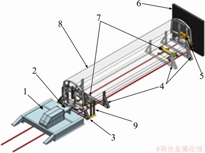
Figure 12 Overall test setup of collision post quasi-static test
Table 4 Equipment list
4.2 Measurement system
To ensure accurate understanding of applied and reaction loads, load cells are utilized at the load application and reaction points, the trolley vertical support points, and the lateral constraint frames. Longitudinal applied and reaction loads are critical data required by the test. To collect these loads, load cells are placed between: 1) the ram and the post; 2) the rigid wall and the reaction end. Vertical load cells are used at each of the 4 airbag suspension locations to determine car mass and distribution throughout the test. To measure any lateral reaction loads generated to resist the applied eccentric collision post load, two load cells are used at the lateral support frame closest to the loading end. Figures 13 and 14 show the position details of the load cells (LCs).
To measure the bending of the collision post during the test, deflection gauges (DGs) are applied at six places along the length of the post, including the top and bottom of the post as well as the location of the maximum predicted deflection. As shown in Figure 15, these gauges are mounted to measure the motion of the post in the direction of the applied force.
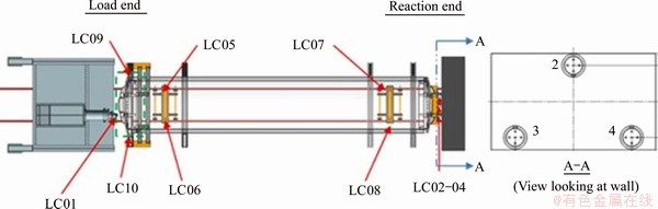
Figure 13 Overall configuration of load cells
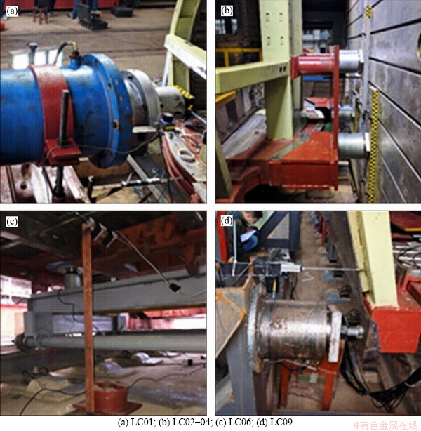
Figure 14 Install position of load cells:
4.3 Results and discussion
4.3.1 Overall structural deformation
The observed post-test deformation response is stable and agrees well with the expected deformation mode from the pretest calculations. Comparisons of the measured and simulated deformation mode of the collision post are shown in Figure 16. Overall the deformation mode and local buckling behavior of the post are very similar. At the same time, no obvious tearing is found in the key parts of the connection. Compared with the results shown in Figure 2 [27], the newly designed scheme effectively protects the safe space of cab cars. This is mainly caused by two reasons. Firstly, the stiffness of the collision post shows the strong- weak-strong distribution under the effect of the induced design. When the crushing force is applied, the plastic hinge appears first in the middle of structure rather than at the root. Therefore, the stress level at the root of the collision column is effectively reduced, and the tearing phenomenon is avoided as well. On the other hand, the simplified structure of the top of the collision post makes the force transmission path clearer and more effective. More crushing force can be transmitted through the roof to the middle of the carbody, instead of focus on the junction of the collision column with the roof. As a result, the ideal bucking model of collision post is obtained.
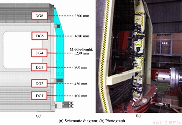
Figure 15 Positions of deflection gauges to measure collision post:
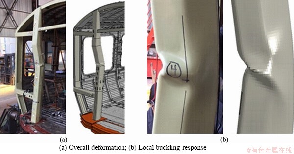
Figure 16 Comparison of simulated and observed overall behavior for test:
4.3.2 Detailed crash responses
The displacement measurements from the test are shown in Figure 17. Consistent with the results predicted by previous analysis, the middle height of the post (DG4) has the maximum longitudinal displacements both at the time of initially and finally unloaded, which are 196.76 and 144.71 mm, respectively.
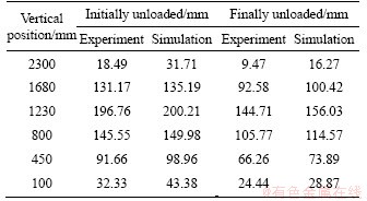
The measured collision post geometry and displacements from simulation and test are compared in Figure 18 and Table 5. Again the mode shape of the response is very similar with slightly larger displacements in the simulation. This is a result of the stiffer boundary conditions in the simulation resulting in larger deformations of the post for similar ram displacements. The peak permanent displacements from both the test measurements and simulation at the middle of the post (DG4) are greater than required (72 mm).
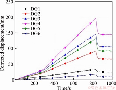
Figure 17 Displacement measurements on collision post
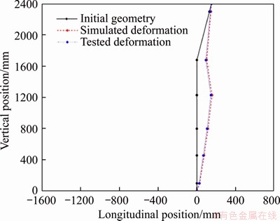
Figure 18 Collision post geometry measurement during test
Table 5 Displacement data of collision post during test
The longitudinal force measurements for the test are shown in Figure 19(a). A primary measurement of the applied load is obtained by a load cell mounted on the loading ram. There are also three load cells on the reaction wall at the far end of the test car which are summed in the figure to calculate the total reaction force shown by the black line. In general, the applied load and reaction force agree reasonably well. However, as the deformation increases, the measured ram force increases from the reaction load to the point where it is approximately 50 kN above the reaction force (out of a total of approximately 800 kN).
The discrepancy of the measured ram and reaction loads is a result of the vertical forces that develop on the ram as the collision post deforms. The rotation of the lower collision post during the test creates a sloped interface where the ram is pushed upward and the forward carbody is pushed downward. This can be seen in the vertical load cell measurements under the front bolster shown in Figure 19(b). The combined vertical force at the front bolster is over 100 kN (not including the initial weight of the test car). In addition, as seen in Figure 19(c), there is a significant asymmetry in the lateral reaction due to the applied eccentric collision post load. As a result, the summed reaction force is the more accurate determination of the applied longitudinal load in the test.
The measured force and displacement (DG2, at ram height) are combined to obtain the force- displacement behavior. The simulated and measured force-displacement curves for the collision post are compared in Figure 20. The comparison shows a good correlation between the simulation and the test. The response remains well above the elastic collision post design load of 334 kN as required by the design specification. But the prediction appears slightly stiffer and stronger than the tested response which is resulted from the stiffer boundary conditions in the simulation resulting in higher load of the collision post. On the other hand, the accelerated loading rate used in the simulation contributed some non-negligible dynamic effects that increase the predicted load. These two main factors cause the discrepancy.
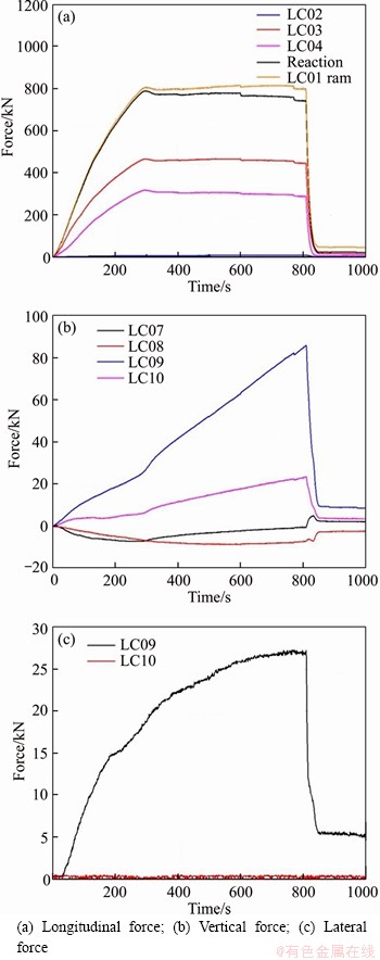
Figure 19 Force measurements for the test:
Besides the evaluation index mentioned in the new stand ASME RT-2-2014, energy absorption efficiency is also an important parameter in crashworthiness design. Generally, the parameter specific energy absorption (SEA) is used to describe the energy dissipation efficiency of an energy absorbing structures. Considering that the main function of the collision post and its attached structure investigated in this paper is to protect the safe space of cab cars, the sensitivity of energy absorption to displacement is worthy of more attention. Therefore, the parameter energy absorption efficiency defined as the energy absorption per unit displacement is proposed and compared with the traditional collision post design.
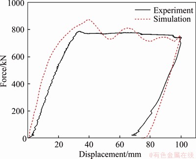
Figure 20 Comparison of simulated and measured force-displacement behaviors
The novel collision post structures can absorb 55.95 kJ of energy in 69.45 mm of permanent deformation. The energy absorption efficiency is 0.81 kJ/mm. Reference [29] gives the relevant data of the past design, the 149.13 kJ of energy is dissipated in 254 mm and the efficiency is 0.58 kJ/mm. Obviously, the novel design has a much higher efficiency in energy absorption. This is mainly because the new design has solved the problem of collision post connection failure. Thus, the energy absorption is greatly increased without fracture.
4.3.3 Light-weight design highlights
The light-weight design is also a part of structural improvement that cannot be ignored. It is difficult to make accurate comparisons because previous designs are based on different standards. But the new design still has many lightweight design highlights. In the new scheme, the AT plate is cancelled and the variable cross lateral beams are alternated. While improving the load transfer, it also reduces a lot of weight. As for the collision post structure, although reinforcing diaphragm is introduced, the variable thickness design has also been realized. The thickness of the lower part is 12 mm, and the upper part is only 4 mm, which reduces the weight of the structure. Finally, the total mass of the collision post structure and the attached beams is 525.06 kg.
5 Conclusions
This work describes the development of a novel collision post structure designed to improve the crashworthiness of subway cab cars. The key conclusions of the paper are as follows.
1) The innovative design of the collision post includes a load transfer improvement that reduces the stress concentration at the joint, and a stiffness induction design, inducing the ideal deformation model.
2) The novel design is evaluated first with finite element analysis, which shows a good performance and provides a test plan for the validate experiment.
3) The experimental results agree well with the simulations, and demonstrate that the novel design can meet all the provisions of the new standard ASME RT-2-2014.
4) The novel design realizes the collaboration of light weight and high performance, which can provide a good reference and demonstration for the evolutionary design in the future.
Contributors
The overarching research goals were developed by XING Jie and XU Ping. YAO Shu-guang and ZHAO Hui provided the theoretical prediction and established the models and calculated the numerical results. XING Jie and LI Ben-huai carried out the experiment and analyzed the measured data. The initial draft of the manuscript was written by XING Jie, ZHAO Hui and WANG Qian-xuan. All authors replied to reviewers�� comments and revised the final version.
Conflict of interest
XING Jie, XU Ping, ZHAO Hui, YAO Shu-guang, WANG Qian-xuan and LI Ben-huai declare that they have no conflict of interest.
References
[1] XIE Su-chao, ZHOU Hui. Impact characteristics of a composite energy absorbing bearing structure for railway vehicles [J]. Composites Part B: Engineering, 2014, 67: 455-463. DOI:10.1016/j.compositesb.2014.08.019.
[2] XU Ping, YANG Cheng-xing, PENG Yong, YAO Shu-guang, ZHANG De-hong, LI Ben-huai. Crash performance and multi-objective optimization of a gradual energy-absorbing structure for subway vehicles [J]. International Journal of Mechanical Science, 2016, 107: 1-12. DOI: 10.1016/ j.ijmecsci.2016.01.001.
[3] XU Ping, YANG Cheng-xing, PENG Yong, YAO Shu-guang, XING Jie, LI Ben-huai. Cut-out grooves optimization to improve crashworthiness of a gradual energy-absorbing structure for subway vehicles [J]. Materials and Design, 2016, 103: 132-143. DOI: 10.1016/j.matdes.2016.04.059.
[4] XIE Su-chao, LIANG Xi-feng, ZHOU Hui, LI Jian. Crashworthiness optimisation of the front-end structure of the lead car of a high-speed train [J]. Structralal and Multidisciplinary Optimization, 2016, 53: 339-347. DOI: 10.1007/s00158-015-1332-y.
[5] LU Zhai-jun, LI Ben-huai, YANG Cheng-xing, ZHAO Hui, XU Ping, YAO Shu-guang, PENG Yong, ZHANG De-hong. Numerical and experimental study on the design strategy of a new collapse zone structure for railway vehicles [J]. International Journal of Crashworthiness, 2017, 22: 488-502. DOI: 10.1080/13588265.2017.1281080.
[6] XU Ping, XING Jie, YAO Shu-guang, YANG Cheng-xing, CHEN Kai, LI Ben-huai. Energy distribution analysis and multi-objective optimization of a gradual energy-absorbing structure for subway vehicles [J]. Thin-Walled Structures, 2017, 115: 255-263. DOI: 10.1016/j.tws.2017.02.033.
[7] YANG Cheng-xing, XU Ping, YAO Shu-guang, XIE Su-chao, LI Qing-ming, PENG Yong. Optimization of honeycomb strength assignment for a composite energy-absorbing structure [J]. Thin-Walled Structures, 2018, 127: 741-755. DOI: 10.1016/j.tws.2018.03.014.
[8] PENG Yong, HOU Lin, CHE Quan-wei, XU Ping, LI Fan. Multi-objective robust optimization design of a front-end underframe structure for a high-speed train [J]. Engineering Optimization, 2018, 1: 1-22. DOI: 10.1080/0305215X.2018. 1495719.
[9] XING Jie, XU Ping, YAO Shu-guang, ZHAO Hui, HUANG Qi, XU Kai, LI Ben-huai. Crashworthiness optimisation of a step-like bi-tubular energy absorber for subway vehicles [J]. International Journal of Crashworthiness, 2019, 4: 1-11. DOI: 10.1080/13588265.2019.1577522.
[10] GAO Guang-jun, ZHUO Tian-yu, GUAN Wei-yuan. Recent research development of energy-absorption structure and application for railway vehicles [J]. Journal of Central South University, 2020, 27(4): 1012-1038. DOI: https://doi.org/ 10.1007/s11771-020-4349-3.
[11] WEBSTER T, FRANCIS M, LOUIS T, ISABEL B, WILLIAM H. Collision of reading company commuter train and tractor-semitrailer, near Yardley Pennsylvania, June 5, 1975 [R]. Washinton D C: National Transportation Safety Board, 1976. https://www.ntsb.gov/investigations/accidentr eports/pages/rar7604.aspx.
[12] HALL J, FRANCIS R, HAMMERSCHMIDT J, GOGLIA J, BLACK G. Railroad accident report near head-on collision and derailment of two new jersey transit commuter trains near secaucus, New Jersey February 9, 1996 [R]. Washinton D C: National Transportation Safety Board, 1997. https:// www.ntsb.gov/investigations/accidentreports/pages/rar9701.aspx.
[13] HALL J, FRANCIS R, HAMMERSCHMIDT J, GOGLIA J, BLACK G. Collision and derailment of Maryland rail commuter MARC Train 286 and national railroad passenger corporation AMTRAK Train 29 near Silver Spring, MD February 16, 1996 [R]. Washinton D C: National Transportation Safety Board, 1997. https://www.ntsb.gov/ investigations/accidentrepor ts/pages/rar9702.aspx.
[14] HALL J, FRANCIS R, HAMMERSCHMIDT J, GOGLIA J, BLACK G. Collision of Northern Indiana commuter transportation district train 102 with a tractor-trailer, Portage, Indiana, June 18, 1998 [R]. Washinton D C: National Transportation Safety Board, 1999. https://www.ntsb.gov/ investigations/accidentreports/pages/rar9903.aspx.
[15] TYRELL D C. Rail passenger equipment accidents and the evaluation of crashworthiness strategies [J]. Proceedings of the Institute of Mechanical Engineers Part F: Journal of Rail and Rapid Transit, 2002, 216: 131-147. DOI: 10.1243/ 09544090260082371.
[16] TYRELL D C, SEVERSEN K J, MAYVILLE R A, STRINGFELLOW R G, BERRY S, PERLMAN A B. Evaluation of cab car crashworthiness design modifications [C]// Proceedings of the 1997 ASME/IEEE Joint Railroad Conference. Boston: 1997, 49-58. DOI: 10.1109/RRCON. 1997.581353.
[17] MAYVILLE R A, RANDOLPH P, JOHNSON K N. Static and dynamic crush testing and analysis of a rail vehicle corner structural element [C]// 8th ASME Symposium on Crashworthiness, Occupant Protection and Biomechanics in Transportation. Nashville: 1999: 1-17. https://rosap.ntl.bts. gov/view/dot/34003.
[18] APTA SS-C&S-034-99. Standard for the design and construction of passenger railroad rolling stock [S]. The American Public Transportation Association, 1999.
[19] MAYVILLE R A, JOHNSON K N, TYRELL D C, STRINGFELLOW R G. Rail vehicle cab car collision and corner post designs according to APTA S-034 requirements [C]// 2003 ASME International Mechanical Engineering Congress & Exposition. Washington, DC: 2003: 44114. DOI: 10.1115/ IMECE2003-55114.
[20] STRINGFELLOW R, AMAR T R. Development and fabrication of state-of-the-art end structures for budd M1 cars [C]// 2008 ASME Rail Transportation Division Fall Technical Conference. Chicago: 2008: 74033. DOI: 10.1115/ RTDF2008-74033.
[21] MARTINEZ E, TYRELL D, ZOLOCK J. Rail-Car impact tests with steel coil: Car crush [C]// 2003 IEEE/ASME Joint Rail Conference. Chicago: 2003: 1656. DOI: 10.1115/ RTD2003-1656.
[22] JACOBSEN K. Rail car impact tests with steel coil: Collision dynamics [C]// 2003 IEEE/ASME Joint Railroad Conference. Chicago: 2003: 1655. DOI: 10.1109/RRCON. 2003.1204652.
[23] TYRELL D. Review of severe deformation recommended practice through analyses [C]// 2005 IEEE/ASME Joint Rail Conference. Pueblo: 2005: 70043. DOI: 10.1109/RRCON. 2005.186062.
[24] MAYRELL R, STRINGFELLOW R, MARTINEZ E. Development of conventional cab car end structure designs for full scale testing [R]. Washinton D C: US Department of Transportation, 2006. https://cms8.fra.dot.gov/sites/fra.dot. gov/files/fra_net/1192/ord0620.pdf.
[25] TYRELL D, MARTINEZ E, JACOBSEN K, PERLMAN B. Passenger cab car grade crossing impact test report [R]. Washinton D C: US Department of Transportation, 2007. https://rosap.ntl.bts.gov/view/dot/8856.
[26] MARTINEZ E, SPONS G, TYRELL D. Train-to-train impact test of crash energy management passenger rail equipment: Structural results [C]// ASME 2006 International Mechanical Engineering Congress and Exposition. Chicago: 2006: 13597. DOI: 10.1115/IMECE2006-13597.
[27] PRIANTE M, LLANA P, JACOBSEN K, TYRELL D, PERLMAN B. A dynamic test of a collision post of a state-of-the-art end frame design [C]// 2008 ASME Rail Transportation Division Fall Technical Conference. Chicago: 2008: 74020. DOI: 10.1115/RTDF2008-74020.
[28] STRINGFELLOW R, PAETSCH C. Modeling material failure during cab car end frame crush [C]// Proceedings of the 2009 ASME Joint Rail Conference. Pueblo: 2009: 63054. DOI: 10.1115/JRC2009-63054.
[29] MUHLANGER M, LLANA P, TYRELL D. Dynamic and quasi-static grade crossing collision tests [C]// Proceedings of the 2009 ASME Joint Rail Conference. Pueblo: 2009: 63035. https://watermark.silverchair.com/115_1.pdf.
[30] ASME RT-2-2014. Safety standard for structural requirements for heavy rail transit vehicles [S]. The American Society of Mechanical Engineers, 2014.
(Edited by FANG Jing-hua)
���ĵ���
��������˾�������ͷ�ײ���ṹ����ײ�������������֤
ժҪ��Ϊ�˸��Ƶ�������˾���ҵ���ײ���ܣ����������һ�����͵ķ�ײ���ṹ��Ʒ������ýṹ�Ĵ���֮����Ҫ�����㣺1) ��ײ�����복�嶥�������Ӹ�Ϊ����ʹ������������Ӻ����������˹ؼ����Ӳ�λ��Ӧ�����У�2) ��ײ�����ڲ��ṹ�����˸ն��յ���Ʒ�����ʹ�����ڳ���ѹ����ʱ���Ի������ı���ģʽ���Ӷ����õı���˾���ҵİ�ȫ�ռ䡣�ڱ����У��Ը����ͷ�ײ���ṹ��������ײ����������Ԫ��������Ӧ��ԭ�ͳ����顣����������ýṹ�ı���ģʽ�ȶ�����Ԥ�Ƶ�����ģʽ�߶�һ�¡�����ʱ������غ�Ϊ874.17kN������ѹ���������غ�ȫ�̸��ڵ�������غ�334kN������֮�⣬�����в�δ�����ԵĽṹ˺��ʧЧ������ˣ�������������ͷ�ײ���ṹ�ܹ������±���ȫ�����Ҫ����Ч���Ƶ�������˾���ҵ���ײ���ܡ�����ĶԸýṹ������Ч���Լ���������Ʒ��������ͬ���������ܽ�����ۡ�
�ؼ��ʣ���ײ���ṹ����������˾���ң���ײ�ԣ���̬����
Foundation item: Project(2016YFB1200505-016) supported by the National Key Research and Development Program of China; Project(51675537) supported by the National Natural Science Foundation of China; Project(2018zzts161) supported by the Independent Exploration and Innovation Project of Central South University, China
Received date: 2019-12-30; Accepted date: 2020-06-09
Corresponding author: WANG Qian-xuan, PhD, Associate Professor; Tel: +86-750-3296296��E-mial: wqxzndx@163.com; ORCID: https://orcid.org/0000-0001-7412-6405
Abstract: This paper proposes a novel collision post structure designed to improve the crashworthiness of subway cab cars. The structure provides two innovative features: 1) a simpler connection between the post and the car roof, which gives a more reasonable load transfer path to reduce the stress concentration at the joint; and 2) a stiffness induction design that provides an ideal deformation model to protect the safe space of the cab cars. The novel collision post structure was evaluated with finite element analysis, and a prototype cab car was mechanically tested. The results demonstrate that the deformation response was stable and agreed well with the expected ideal mode. The maximum load was 874.17 kN and the responses remained well above the elastic design load of 334 kN as required by the design specification. In addition, there was no significant tearing failure during the whole test process. Therefore, the novel collision post structure proposed has met the requirements specified in new standard to improve the crashworthiness of subway cab cars. Finally, the energy absorption efficiency and light weight design highlights were also summarized and discussed.
