
J. Cent. South Univ. (2016) 23: 2083-2091
DOI: 10.1007/s11771-016-3264-0

Lateral load-carrying capacity analyses of composite shear walls with double steel plates and filled concrete with binding bars
ZHOU De-yuan(�ܵ�Դ), LIU Ling-fei(�����), ZHU Li-meng(������)
College of Civil Engineering, Tongji University, Shanghai 200092, China
 Central South University Press and Springer-Verlag Berlin Heidelberg 2016
Abstract:
A method is developed to predict the lateral load-carrying capacity of composite shear walls with double steel plates and filled concrete with binding bars (SCBs). Nonlinear finite element models of SCBs were established by using the finite element tool, Abaqus. Tie constraints were used to connect the binding bars and the steel plates. Surface-to-surface contact provided by the Abaqus was used to simulate the interaction between the steel plate and the core concrete. The established models could predict the lateral load-carrying capacity of SCBs with a reasonable degree of accuracy. A calculation method was developed by superposition principle to predict the lateral load-carrying capacity of SCBs for the engineering application. The concrete confined by steel plates and binding bars is under multi-axial compression; therefore, its shear strength was calculated by using the Guo-Wang concrete failure criterion. The shear strength of the steel plates of SCBs was calculated by using the von Mises yielding criterion without considering buckling. Results of the developed method are in good agreement with the testing and finite element results.
Key words:
1 Introduction
The reinforced concrete (RC) shear wall is a traditional lateral force resisting system. Various new techniques have been developed in order to improve mechanical properties of RC shear walls. The steel plate reinforced concrete shear wall is a promising alternative due to its good mechanical properties (strength, stiffness and ductility).
According to the position relationship between the steel plate and the concrete [1], the steel plate RC shear wall can be roughly divided into three categories as shown in Fig. 1: 1) the steel plate is located in the center of cross section of the shear wall [2-3]; 2) the steel plate is located at one side of the shear wall [4-5]; 3) the steel plate is located at two sides of the shear wall [6-8].
Various types of composite shear walls with double steel plates and filled concrete have been studied in literature. WRIGHT [9] reported the study on composite walls with two skins of profiled steel sheets. Their testing results indicate that the full axial capacity cannot be achieved due to the low interface bond strength. The Bi-steel composite wall was proposed by PRYER [10]. In this wall configuration, shear connectors are welded between two steel plates and concrete is poured after the wall is installed in place. High shear strength and good ductility were reported to be achieved. JI et al [11] proposed and tested the steel tube-double steel plate- concrete composite wall. The steel tube filled with concrete was placed in boundary elements, which can significantly increase the horizontal bearing capacity. EMORI [12] conducted tests on concrete filled steel box walls and EOM et al [13] studied seismic behaviors of double skin composite walls. Additionally, numerical and experimental studies of composite shear walls were reported in the research work of CLUBLEY et al [14], ARABZADE et al [15], and RAFIEI et al [16].
The composite shear wall with double steel plates and filled concrete with binding bars (SCBs) is one type of composite shear walls with double steel plates and filled concrete. The concrete and the binding bars restrain the local buckling of the steel plates. The concrete confined by the steel plates is under multi-axial compression. Therefore, the wall is expected to have good ductility, energy dissipation capacity and high shear strength.
The study of this paper is following-up work of the experiment carried out in Tongji University. The object of this study is to develop a method to predict the lateral load-carrying capacity of SCBs. Nonlinear finite element models of SCBs under in-plane loadings were established in Abaqus. The calculation method was developed for the lateral load-carrying capacity of SCBs and was verified by the comparison with the finite element analyses and the experiment results.
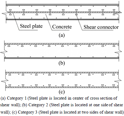
Fig. 1 Main types of steel plate RC shear wall:
2 Numerical analyses of SCBs
2.1 SCB testing program
Ten specimens of SCBs were designed and tests were conducted on wall specimens subjected to axial loading and horizontal low cyclic loading to study the seismic behaviors in consideration of the effect of cross section thickness, aspect ratio, steel plate thickness, space between binding bars, section steel, core concrete thickness and axial compression ratio by ZHU et al [17] (Figs. 2 and 3). The details of the specimens are shown in Table 1.
2.2 Finite element modeling
Nonlinear finite element analyses of SCBs are established in Abaqus 6.10 with the damaged plasticity model for concrete to develop reliable models forpredicting the lateral load-carrying capacity of the SCB (Fig. 4).
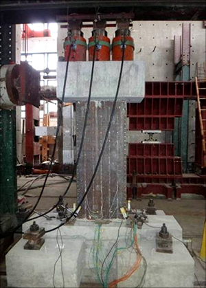
Fig. 2 Photo of SCB
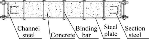
Fig. 3 Cross section of SCB
Shell element S4 was used to simulate the steel plates, the section steels and the channel steels. Truss element T3D2 was applied in the simulation of the binding bars. 3D stress element C3D8 was used to simulate the concrete. Embedded constraints were used to embed the binding bars and the section steels in the core concrete and to embed the steel plates, the channel steels, the section steels in the loading beam and bottom beam as well. Tie constraints were used to connect the binding bars and the steel plates. Surface-to-surface contacts provided by Abaqus were used to simulate the interaction between the steel plate and the core concrete in both the normal direction and the tangential direction. The hard contact was used to simulate the contact of the normal direction, which can transfer the pressure between the contact surfaces. The Coulomb friction model was used to simulate the friction of the tangential direction. Shear stress is transferred between the interfaces without sliding until the shear stress reaches a critical value ��crit:
 (1)
(1)
where �� is friction coefficient which equals 0.6 [18]; p is the pressure between the contact surfaces.
Table 1 Specimen design
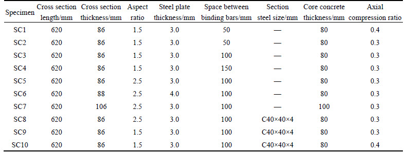
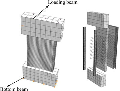
Fig. 4 Finite element model
All six degrees of freedom of bottom surface were constrained since the bottom beam was fixed by 4 screws in the testing. The uniform axial pressure was applied to the top surface of the loading beam. The lateral load or displacement was applied to one side of the loading beam.
Steel and concrete were modeled in the finite element method (FEM) analyses by following the constitutive laws that were explained as follows.
1) The damaged plasticity concrete model (DAPL) was used for concrete. The dilation angle of concrete is 30��. The uniaxial compressive stress-strain curve of concrete used in the analyses is shown in Fig. 5 and Eq. (2) [19]. The uniaxial tensile stress-strain curve of concrete used in the analyses is shown in Fig. 6 and Eq. (3).
 (2)
(2)
where 

 10-6;
10-6;
 fc= uniaxial compressive strength of concrete; ��c0=peak compressive strain of concrete; ��a and ��d are parametersin the stress-strain curve. In this study, fc=24 MPa; ��c0=1.54��10-3; ��a=2.1; ��d=0.998.
 (3)
(3)
where x=��t/��t0; y=��t/ft; 
 ft is the tensile strength of concrete; ��t0 is the peak tensile strain; ��t is a parameter of the tensile stress-strain curve. In this study, ft=2.638 MPa; ��t0=1.1��10-4; ��t=2.171.
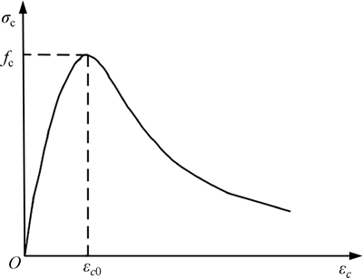
Fig. 5 Uniaxial compressive stress-strain curves of concrete
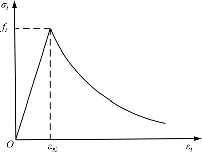
Fig. 6 Uniaxial tensile stress-strain curves of concrete
2) The von Mises yielding criterion was used for the steel. The uniaxial stress-strain relationship for the steel was assumed as a bi-linear model as shown in Fig. 7. In this work, the elastic modulus of the steel is 200�� 103 MPa or 0 for the cases of pre-yielding or post- yielding, respectively; fy are 321.7 MPa, 259.8 MPa and 322.4 MPa for the 3 mm steel plate, the 4 mm steel plate and the channel steel, respectively.
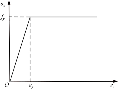
Fig. 7 Uniaxial compressive stress-strain curves of steel
2.3 Comparisons between FEM results and testing results
Comparisons between the FEM results for specimens SC1-SC10 under the monotonic loading and the testing results for specimens SC1-SC10 are shown in Fig. 8. Moreover, the FEM results for specimens SC1-SC10 under the monotonic loading and the skeleton curves for specimen SC1-SC10 obtained from the tests are shown in Fig. 9. In Figs. 8 and 9, ��EXP�� represents the testing result while ��FEM�� represents the FEM result.
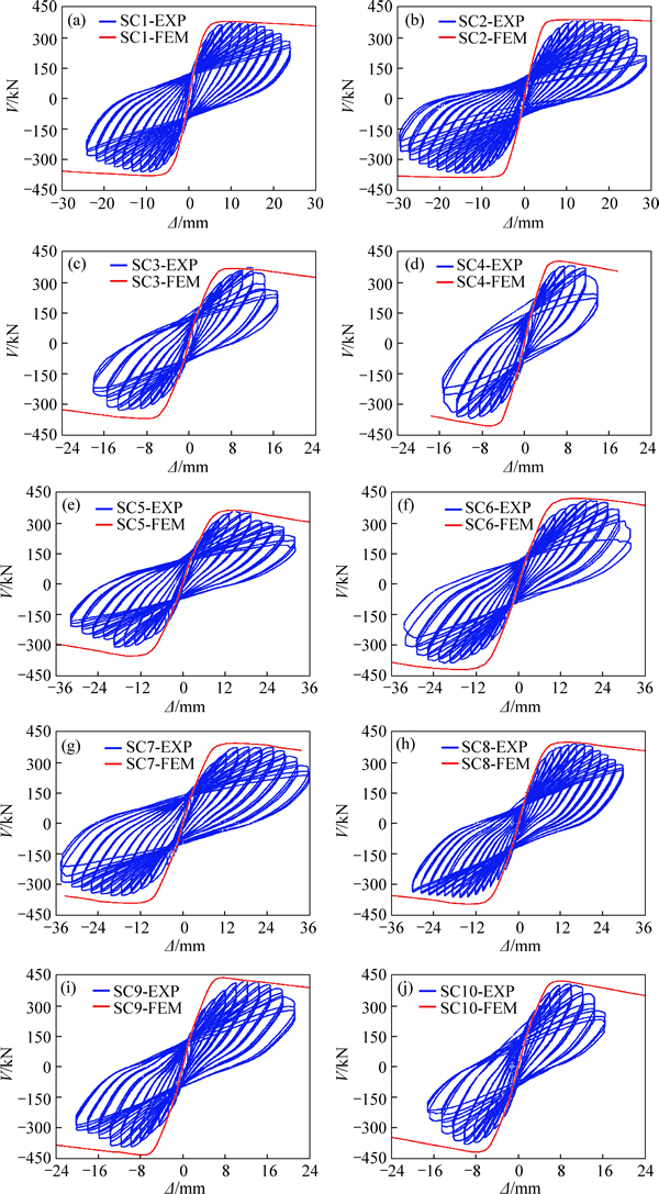
Fig. 8 Comparisons between FEM results and testing results
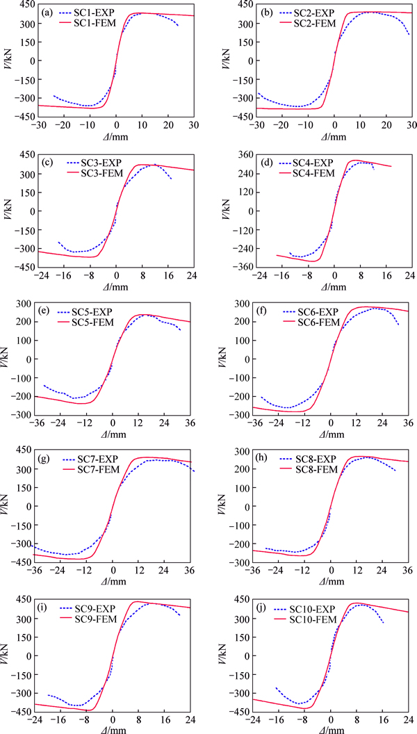
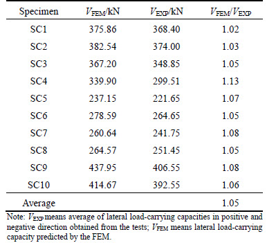
Fig. 9 Comparisons between FEM results and skeleton curves Comparisons of the lateral load-carrying capacities (the maximum loads) between the FEM results and the testing results are shown in Table 2. It can be seen that the FEM could provide a reasonable estimation of the lateral load-carrying capacities of SCBs.
Table 2 Comparisons of lateral load-carrying capacities between FEM results and the testing results
3 Development of load-carrying capacity calculation method
Although the finite element analysis can predict the lateral load-carrying capacity of SCBs with a reasonable degree of accuracy, a simple method is desirable for engineering applications. Therefore, a calculation method was developed in this work based on the superposition principle.
The lateral load-carrying capacity Vf,THE of SCBs consists of contributions from the steel plates and the core concrete:
 (4)
(4)
where Ac is the area of the core concrete; As is the area of the steel plates; ��c is the shear strength of the core concrete; ��s is the shear strength of the steel plates; �� is the modification factor of bending effect.
3.1 Basic assumptions
A coordinate system was established as shown in Fig. 10. In order to predict the lateral load-carrying capacity, three assumptions were made as follows:
1) The restrain stress of the core concrete is non- uniform. In order to simplify the study, the core concrete stress values in both the x direction (��cx) and the y direction (��cy) were assumed to distribute uniformly (Fig. 11).
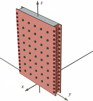
Fig. 10 Coordinate system
2) Since the axial load is far less than ultimate axial load (Table 1), the SCB is assumed to be in the elastic state under the axial compressive force. Therefore, the steel plate stress in the z direction (��sz) and the core concrete stress in the z direction (��cz) could be calculated according to their elastic models.
3) According to the testing result, it was assumed that the binding bars yield when the SCB reaches the state of lateral load-carrying capacity.
3.2 Calculation of core concrete shear stress ��c
Take a unit area (the shaded region in Fig. 11) to calculate the core concrete stress in the x direction (��cx). It could be determined by equilibrium condition:
 (5)
(5)
where l is the side length of the y direction of core concrete in xy cross section; az is the height of the shaded region; nb is the number of the binding bars in the unit area; ��b is the stress of the binding bars; Ab is the cross section area of the binding bars. ��cy could also be determined in the same way.
��cz, the core concrete stress in the z direction, was obtained by the second assumption. ��1, ��2 and ��3, the principal stresses of the core concrete, as shown in Fig. 12, were determined by Eqs. (6)-(8) with one quantity ��c:
 (6)
(6)
 (7)
(7)
 (8)
(8)
Because the expression is simple, easy to use and the parameters have clear physical and geometric meaning, the five-parameter failure criterion for concrete proposed by GUO and WANG [19] was adopted in the study, which was expressed by Eqs. (9)-(13). The core concrete shear stress ��c can be determined based on these equations.
 (9)
(9)
 (10)
(10)
 (11)
(11)
 (12)
(12)
 (13)
(13)
where a=6.9638; b=0.09; ct=12.2445; cc=7.3319; d=0.9297; fc is the compressive strength of the core concrete.
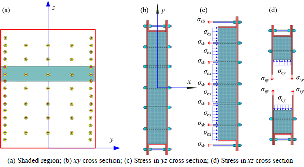
Fig. 11 Stress state of core concrete and steel plate:
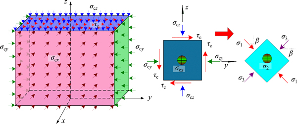
Fig. 12 Stress state of core concrete
3.3 Calculation of steel plate shear strength ��s
Stresses of the steel plates are shown in Fig. 13. The stress of the steel plates in the z direction, ��sz, can be determined by the second assumption. The von Mises yielding criterion (Eq. (14)) could be applied to calculate the shear strength of the steel plates.
 (14)
(14)
where fy is the yield stress of the steel plates. In Eq. (14), ��sy is unknown.
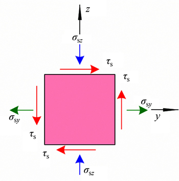
Fig. 13 Stress state of steel plate
3.4 Procedure to estimate lateral load-carrying capacity of SCB
Based on the superposition principle, the lateral load-carrying capacity of the SCB can be estimated with the core concrete shear stress ��c and the steel plate shear strength ��s. Steps to calculate the lateral load-carrying capacity of the SCB are shown in Fig. 14.
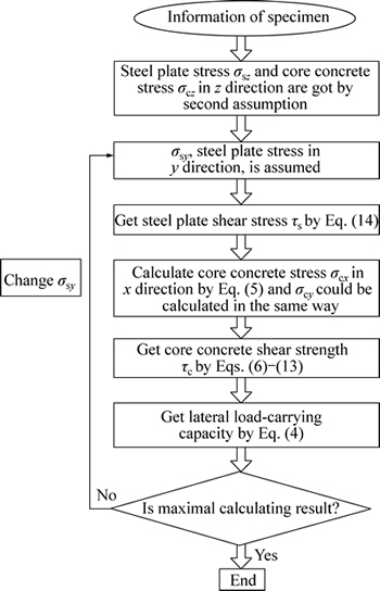
Fig. 14 Flow chart of calculating lateral load-carrying capacity of SCB
Consider the bending effect, the parameter �� of Eq. (4) is determined by
 (15)
(15)
where a is the aspect ratio.
Equation (4) can be expressed as
 (16)
(16)
3.5 Result comparisons
The lateral load-carrying capacities of ten specimens were estimated by the developed method. Comparisons between the results of the developed method, the FEM and the tests are shown in Table 3. It is indicated that the results obtained from the developed method are in good agreement with the testing results. Most of the results of the developed method are larger.
Table 3 Comparisons between results of developed method, FEM and tests
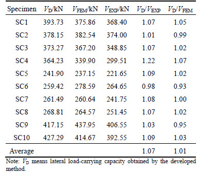
The reasons are that the effect of initial imperfection and buckling of the steel plates were not considered.
4 Summary and conclusions
1) The FEM results have good agreement with the testing results. The ratio of the prediction results to the corresponding testing results ranges from 1.02 to 1.13 with a mean value of 1.05. The finite element models can be used to predict the lateral load-carrying capacity of the SCB.
2) The developed method can be used to calculate the lateral load-carrying capacity of the SCB with a reasonable degree of accuracy. The ratio of the prediction results to the corresponding testing results ranges from 0.98 to 1.22 with a mean value of 1.07.
3) Compared to the FEM, the developed method is simple and feasible for the engineering application.
4) Further research for the developed method considering the effect of initial imperfection and buckling of the steel plate is required to improve the method.
References
[1] NIE Jian-guo, TAO Mu-xuan, FAN Jian-sheng, BU Fan-min, HU Hong-song, MA Xiao-wei, LI Sheng-yong, LIU Fu-jun. Research advances of composite shear walls with double steel plates and filled concrete [J]. Building Structure, 2011, 41(12): 52-60. (in Chinese)
[2] SUN Fei-fei, LI Guo-qiang, GAO Hui. Test research on seismic behavior of two-sided composite steel plate walls [C]// Proceedings of the 3rd International Conference on Steel and Composite Structures. Manchester, 2007: 805-811.
[3] DEAN R G, POLAND C D, CANON T J. Unusual structural aspects of H.C. Moffit Hospital [C]// Proceedings of the 46th Annual Convention of the Structural Engineers Association of California. Coronado: SEAOC, 1977.
[4] ASTANEH-ASL A. Seismic behavior and design of steel shear walls [C]// The 2001 Structural Engineers Association of California Seminar. San Francisco: SEAONC, 2001.
[5] ZHAO Q H, ASTANEH-ASL A. Cyclic behavior of traditional and innovative composite shear walls [J]. Journal of Structural Engineering, 2004, 130(2): 271-284.
[6] WRIGHT H D, ODUYEMI T O S, EVANS H R. The test behavior of double skin composite elements [J]. Journal of Constructional Steel Research, 1991, 19 (2): 97-110.
[7] WRIGHT H D, ODUYEMI T O S, EVANS H R. The design of double skin composite elements [J]. Journal of Constructional Steel Research, 1991, 19(2): 111-132.
[8] CLUBLEY S K, MOY S S J, XIAO R Y. Shear strength of steel-concrete-steel composite panels. Part I-testing and numerical modeling [J]. Journal of Constructional Steel Research, 2003, 59(6): 781-794.
[9] WRIGHT H D. The behavior of composite walling under construction and service loading [J]. Journal of Constructional Steel Research, 1995, 35(3): 257-277.
[10] PRYER J W. The development and use of British steel bi-steel [J]. Journal of Constructional Steel Research, 1998, 46(1/2/3): 15.
[11] JI Xiao-dong, JIANG Fei-ming, QIAN Jia-ru. Seismic behavior of steel tube-double steel plate-concrete composite walls: Experimental tests [J]. Journal of Constructional Steel Research, 2013, 86(7): 17-30.
[12] EMORI K. Compressive and shear strength of concrete filled steel box wall [J]. Steel Structures, 2002, 26(2): 29-40.
[13] EOM T S, PARK H G, LEE C H, KIM J H, CHANG I H. Behavior of double skin composite wall subjected to in-plane cyclic loading [J]. Journal of Structural Engineering, 2009, 135(10): 1239-1249.
[14] CLUBLEY S K, MOY S S J, XIAO R Y. Shear strength of steel- concrete-steel composite panels. Part II-detailed numerical modeling of performance [J]. Journal of Constructional Steel Research, 2003, 59(6): 795-808.
[15] ARABZADE A, MOHARAMI H. AYAZI A. Local elastic buckling coefficients of steel plates in composite steel plate shear walls [J]. Scientia Iranica A, 2011, 18(1): 9-15.
[16] RAFIEI S, HOSSAIN K M A, LACHEMI M, BEHDINAN K, ANWAR M S. Finite element modeling of double skin profiled composite shear wall system under in-plane loadings [J]. Engineering Structures, 2013, 56: 46-57.
[17] ZHU Li-meng, ZHOU De-yuan, HE Ming-yue. Test research on seismic behavior of low shear-span ratio composite shear wall with double steel platesand infill concrete [J]. Journal of Building Structures, 2013, 34(6): 93-102. (in Chinese)
[18] RABBAT B G, RUSSELL H G. Friction coefficient of steel on concrete or grout [J]. Journal of Structural Engineering, 1985, 111(3): 505-515.
[19] GUO Zhen-hai, WANG Chuan-zhi. Investigation of strength and failure criterion of concrete under multi-axial stress [J]. China Civil Engineering Journal, 1991, 24 (1): 1-14. (in Chinese)
(Edited by YANG Hua)
Foundation item: Project(51178333) supported by the National Natural Science Foundation of China; Project(SLDRCE09-D-03) supported by the Ministry of Science and Technology of China
Received date: 2015-08-10; Accepted date: 2015-11-10
Corresponding author: LIU Ling-fei, PhD Candidate; Tel: +86-18301796010; E-mail: liulingfeitj@163.com
Abstract: A method is developed to predict the lateral load-carrying capacity of composite shear walls with double steel plates and filled concrete with binding bars (SCBs). Nonlinear finite element models of SCBs were established by using the finite element tool, Abaqus. Tie constraints were used to connect the binding bars and the steel plates. Surface-to-surface contact provided by the Abaqus was used to simulate the interaction between the steel plate and the core concrete. The established models could predict the lateral load-carrying capacity of SCBs with a reasonable degree of accuracy. A calculation method was developed by superposition principle to predict the lateral load-carrying capacity of SCBs for the engineering application. The concrete confined by steel plates and binding bars is under multi-axial compression; therefore, its shear strength was calculated by using the Guo-Wang concrete failure criterion. The shear strength of the steel plates of SCBs was calculated by using the von Mises yielding criterion without considering buckling. Results of the developed method are in good agreement with the testing and finite element results.
