
J. Cent. South Univ. Technol. (2008) 15: 339-343
DOI: 10.1007/s11771-008-0064-1
![]()
Failure of rock under dynamic compressive loading
ZHOU Zi-long(������)1, LI Di-yuan(���Ԫ)1, MA Guo-wei(����ΰ)2, LI Jian-chun(���)2
(1. School of Resources and Safety Engineering, Central South University, Changsha 410083, China;
2. School of Civil and Environmental Engineering, Nanyang Technological University,
Nanyang Avenue, 639798, Singapore)
Abstract:
Split Hopkinson Pressure Bar(SHPB) test was simulated to investigate the distribution of the first principal stress and damage zone of specimen subjected to dynamic compressive load. Numerical models of plate-type specimen containing cracks with inclined angles of 0?, 45? and 90? were also established to investigate the crack propagation and damage evolution under dynamic loading. The results show that the simulation results are in accordance with the failure patterns of specimens in experimental test. The interactions between stress wave and crack with different inclined angles are different; damage usually appears around the crack tips firstly; and then more damage zones develop away from the foregoing damage zone after a period of energy accumulation; eventually, the damage zones run through the specimen in the direction of applied loading and split the specimen into pieces.
Key words:
1 Introduction
Failure of rock under static compressive load has been widely observed in laboratory tests and in situ projects, and has received considerable attention[1-4]. Various models and fracture criteria have been proposed in an attempt to capture the essential mechanism[5-10]. However, due to the complicated process of rock failure, the topic is still the hotspot of recent research and debate[11-13]. For rock failure under dynamic compressive loading, the mechanism is even more complex, and so far there is little knowledge about it.
From experiments of rock with Split Hopkinson Pressure Bar(SHPB), it was found that specimen usually breaks into two halves under lower dynamic loading, and then breaks into more sheet-like or bar-like pieces with increasing dynamic loading[14-15]. As well-known, in hydrostatic compression, no fracture will occur under the highest pressure, even for brittle materials. So it is reasonable to owe the rock failure to the tensile splitting intuitively. However, the failure process and mechanism behind these phenomena are still unknown.
In this paper, a numerical model for SHPB test was established with LS-DYNA to investigate the stress distribution and damage evolution of specimen. At the same time, as the microcracks and inhomogeneities always dominate the failure process of rock-like material,
models of plate-type specimen with different cracks were also simulated to show the crack propagation and damage evolution under dynamic compressive loading, in an attempt to find out the mechanism behind the failure process.
2 Stress distribution and damage evolution of specimen in SHPB test
2.1 Numerical model of SHPB test
SHPB test is a kind of widely used dynamic compression test method of material and its principle can be found in a lot of references[16-18]. The test equipment basically consists of a striker, an input bar, an output bar and a specimen sandwiched between the two bars. The established numerical model of the setup is shown in Fig.1, where the half-sine stress wave(Fig.1(b)) was directly applied to the end of input bar[19]. The stress wave had a peak value of 200 MPa and time span of 200 ��s. The input bar and output bar were both 50 mm in diameter and 1 m in length, with density of 7 700 kg/m3, Poisson��s ratio of 0.285 and elastic modulus of 250 GPa. For the specimen with dimensions of 25 mm in length and 50 mm in diameter, the material properties of self- defined damage model were the same as those in Ref.[20].
2.2 Numerical simulation results
For rock material, the compressive strength is
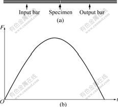
Fig.1 Constructed numerical model of SHPB test: (a) Con- figuration of SHPB test; (b) Applied stress wave (F and t are the scalar force and the time, respectively)
usually several times of its tensile strength. So the first principal stress in specimen is an important factor to cause the material failure. Fig.2 gives the dynamic evolution of the first principal stress and damage of specimen during the dynamic loading.
It can be seen that the stress distribution in specimen is very complex during the stress wave passing through. The first principal stress spreads like spokes of wheel and becomes larger and larger. The damage appears at the outer periphery firstly, and then develops to the center gradually.
At the same time, it can be seen that the damage evolution in specimen is not uniform. When the damage zones happen to encounter the original micro-flaws, the specimen will likely break into halves or sheet-like piece directly. Otherwise, it will crash into dust when the loading rate is high enough.
In this model, the specimen was homogeneous without micro-flaws aiming at investigating the stress distribution and evolution mainly. The damage evolution considering crack presence will be analyzed further in the following paragraphs.
3 Crack propagation under dynamic com- pressive loading
Rock normally contains micro-flaws, which may be grain boundary mismatches, low aspect-ratio cavities, micro-cracks, and soft and hard inclusions. All these micro-flaws can be treated as cracks. Since Griffith��s successful explanation of material failure with crack propagation, rock failure was usually owed to fracture and has been studied with fracture mechanics of crack from various points of view[5-9]. Here, plate-type specimens with crack at different angles were simulated to investigate the crack propagation under dynamic compressive loading.
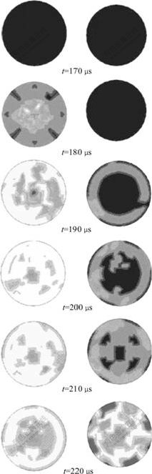
Fig.2 The first principal stress and damage evolution of specimen (view from the end where stress wave transmits in, left column showing the first principal stress and right column showing the damage evolution)
3.1 Description of model configuration and crack geometry
As shown in Fig.3, one plate of 25 mm in height, 50 mm in width and 1 mm in thickness was fabricated with inclined crack at center. Based on SHPB test, the stress wave of Fig.1(b) was applied at the top end of the plate with a fixed bottom end. The crack was simplified into a rectangular pore with 4.0 mm in length and 0.2 mm in width and inclined at angle (��) of 0?, 45?, and 90?, respectively.
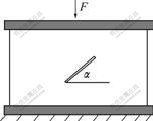
Fig.3 Numerical model of plate-type specimen with crack (F is the applied stress wave; �� is the inclined angle of crack)
3.2 Stress wave interaction and crack propagation
In Fig.4, the early-stage stress distributions of specimen containing different cracks are given, where different colors indicate different stress levels. From these figures, the interaction between stress wave and crack can be seen clearly. When the stress wave reaches the crack with inclined angle of 0?, it is reflected back as tensile stress and superposed with the original compressive stress wave, so there is one disturbed stress zone around the crack lasting all along. The same disturbed zone can be investigated for the crack with inclined angle of 45?. But for the crack inclined at angle of 90?, the stress wave passes through the crack without being disturbed at the early stage.
Because the interaction mechanisms between stress wave and cracks with different inclined angles are different, the damage evolutions in plate-type specimens are also different. Fig.5 shows the damage evolution of plate-type specimens with different cracks.
It can be seen from Fig.5 that, damage develops more quickly in plate-type specimen with crack of inclined angle of 0? or 45? than that with crack of 90? inclined angle. The damage of material does not take place continuously with time. There are usually two stages of damage evolution. The damage caused by cracks occurs firstly around the crack tips, and then some new damage zones appear suddenly far from the crack. As can be seen in Fig.5(a), damage takes place firstly at crack tips and at time of 4 ��s, then the damage zone enlarges around the crack in time span from 5 to 25 ��s. After a period of energy accumulation, more damage zones appear suddenly far from the foregoing damage
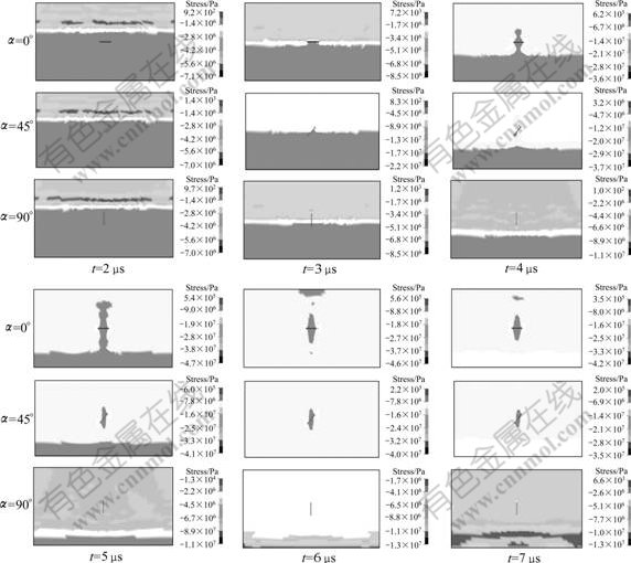
Fig.4 Early stage stress distribution in plate-type specimens with different cracks
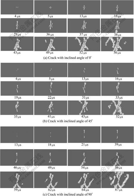
Fig.5 Damage evolution in plate-type specimens with crack of different inclined angles
zone at time of 36 ��s. For Fig.5(b) and Fig.5(c), suddenly-appeared damage zones can also be found at time of 41 and 49 ��s, respectively.
From the above, one common phenomenon can be observed that, all the damage zones propagate along the direction of applied dynamic compressive loading and eventually split the specimens into pieces. It should be pointed out that, although the inclined angles of the crack are different, the final failure patterns of specimens are rather similar, i.e. 56 ��s of Fig.5(a), 52 ��s of Fig.5(b) and 64 ��s of Fig.5(c).
4 Conclusions
1) Stress distributions and damage evolution of specimens in SHPB test are investigated numerically to unveil the failure mechanism of specimen under dynamic compressive loading.
2) Under dynamic compressive loading, rock tends to have splitting failure model. The first principal stress and damage distribution pattern of specimen from simulation are in accordance with the experiment results.
3) For specimens with cracks of different inclined angles, the interactions between stress wave and crack are complex and different.
4) For specimen with crack, its damage usually appears around the crack tips firstly, and then the damage zones develops away from the forgoing damage zone after a period of energy accumulation.
References
[1] Brace W F, Bombolakis E G. A note on brittle crack growth in compression [J]. Journal of Geophysical Research, 1963, 68(12): 3709-3713.
[2] Fairhurst C, Cook N G. Phenomenon of rock splitting parallel to direction of maximum compression in neighbourhood of surface [C]// MANUEL R. Proceedings of the 1st Congress of International Society of Rock Mechanics. Lisbon: Springer, 1966, 3(1): 687-692.
[3] Holzhausen G R, Johnson A M. Analysis of longitudinal splitting of uniaxially compressed rock cylinder [J]. Int J Rock Mech Min Sci Geom Abst, 1979, 16(1): 63-170.
[4] Adams G R, Jager A J. Petroscopic observation of rock fracturing ahead of stope faces in deep-level gold mines [J]. J South African Inst Min Metall, 1980, 80(6): 204-209.
[5] Nemat-Nasser S, Horii H. Rock failure in compression [J]. Int J Eng Sci, 1984, 22(8/10): 999-1011.
[6] Ashby M F, Hallam S D. The failure of brittle solids containing small cracks under compressive stress state [J]. Acta Metallurgica, 1986, 34(3): 497-510.
[7] Fredrich T, Evens B, Wong T. Effect of grain size on brittle and semibrittle strength: Implication for micromechanics modeling of failure in compression [J]. Journal of Geophysical Research, 1990, 95(B7): 10907-10920.
[8] Deng H, Nemat-Nasser S. Dynamic damage evolution of solids in compression: Microcracking, plastic flow, and brittle-ductile transition [J]. Journal of Engineering Materials and Technology: Transaction of the ASME, 1994, 116(3): 286-289.
[9] Wang E Z, Shrive N G. Brittle fracture in compression: Mechanisms, models and criteria [J]. Engineering Fracture Mechanics, 1995, 52(6): 1107-1126.
[10] Nikitin L V, Odintsev V N. A dilatancy model of tensile macrocracks in compressed rock [J]. Fatigue and Fracture of Engineering Materials and Structures, 1999, 22(11): 1003-1009.
[11] Li Yin-ping, Chen Long-zhu, Wang Yuan-han. Experimental research on pre-cracked marble under compression [J]. International Journal of Solids and Structures, 2005, 42(9/10): 2505-2516.
[12] Zhou Xiao-ping, Wang Jian-hua. Study on the coalescence mechanism of splitting failure of crack-weakened rock subjected to compressive loads [J]. Mechanics Research Communications, 2005, 32(2): 161-171.
[13] Wong R H, Lin P, Tang C A. Experimental and numerical study on splitting failure of brittle solids containing single pore under uniaxial compression [J]. Mechanics of Materials, 2006, 38(1/2): 142-159.
[14] LI Xi-bing, GU De-sheng. Rock impact dynamics [M]. Changsha: Central South University of Technology Press, 1994. (in Chinese)
[15] Li X B, Lok T S, Zhao J. Dynamic characteristics of granite subjected to intermediate loading rate [J]. Rock Mechanics and Rock Engineering, 2005, 38(1): 21-39.
[16] Li X B, Lok T S, Zhao J, ZHAO P J. Oscillation elimination in the Hopkinson bar apparatus and resultant complete dynamic stress-strain curves for rocks [J]. International Journal of Rock Mechanics and Mining Sciences, 2000, 37(7): 1055-1060.
[17] LI Xi-bing, LIU De-shun, GU De-sheng. Effective method of eliminating the oscillation of rock under dynamic stress��strain�� strain rate curves [J]. Journal of Central South University of Technology: Natural Science, 1995, 26(4): 457-460. (in Chinese)
[18] LOK T S, LI X B, LIU D, ZHAO P J. Testing and response of large diameter brittle materials subjected to high strain rate [J]. Journal of Materials in Civil Engineering(ASCE), 2001, 14(3): 262-269.
[19] LI Xi-bing, ZHOU Zi-long, WANG Wei-hua. Construction of ideal striker for SHPB device based on FEM and neural network [J]. Chinese Journal of Rock Mechanics and Engineering, 2005, 24(23): 4215-4219. (in Chinese)
[20] ZUO Yu-jun, LI Xi-bing, ZHOU Zi-long, MA Chun-de, ZHANG Yi-ping, WANG Wei-hua. Damage and failure rule of rock undergoing uniaxial compressive load and dynamic load [J]. Journal of Central South University of Technology, 2005, 12(6): 742-748.
(Edited by YANG Hua)
Foundation item: Projects(50534030, 50674107, 50490274) supported by the National Natural Science Foundation of China; Project(06JJ3028) supported by the Provincial Natural Science Foundation of Hunan, China
Received date: 2007-11-17; Accepted date: 2008-01-28
Corresponding author: ZHOU Zi-long, PhD; Tel: +86-731-8877276; E-mail: zlzhou@mail.csu.edu.cn
