
Trans. Nonferrous Met. Soc. China 30(2020) 1857-1872
Cross-sectional structure, microstructure and mechanical property evolutions of brass cladding pure copper stranded wire composite
during drawing
Yan-bin JIANG1,2 , Yong-shuai LI2 , Yu LEI2 , Jian-xin XIE2,3
1. School of Materials Science and Engineering, Central South University, Changsha 410083, China;
2. Key Laboratory for Advanced Materials Processing of Ministry of Education, University of Science and Technology Beijing, Beijing 100083, China;
3. Beijing Laboratory of Metallic Materials and Processing for Modern Transportation, University of Science and Technology Beijing, Beijing 100083, China
Received 5 September 2019; accepted 18 May 2020
Abstract:
A solid/liquid continuous casting and composite technology was used to produce d8.5 mm brass cladding pure copper stranded wire composite billet and the composite billet was then drawn. The results showed that the composite billet had good surface quality, metallurgical bonding interface between brass and pure copper as well as elongation of 53.1%. Synergistic deformation degree between pure copper wire and brass cladding layer was high during drawing. With an increase of the total deformation amount, the plastic deformation of the pure copper wire reduced triangular arc gaps between the pure copper wires and the triangular arc gaps were fully filled at 50%. When the total deformation amount was increased to 63%, dislocation cells and microbands successively formed in the pure copper wire. In the brass cladding layer, planar dislocation networks, twins and shear bands formed successively, and the main deformation mechanisms were dislocation sliding, twinning and shear deformation. The tensile strength increased from 240 MPa of the composite billet to 519 MPa of the one with the deformation amount of 63%, but the elongation decreased from 53.1% to 3.2%. A process of solid/liquid continuous casting and composite forming��drawing can work as a new compact method to produce brass cladding pure copper stranded wire composite as railway through grounding wire.
Key words:
solid/liquid continuous casting; composite wire; deformation; microstructure evolution; mechanical properties;
1 Introduction
Railway through grounding wire is a kind of cable used for the unified grounding of mechanical and electrical equipments on the whole railway line, which can eliminate signal interference and hidden danger caused by the potential difference between different equipments, and works as the key material for ensuring the safety of railway operation and realizing high speed, heavy load and communication intellectualizing of trains [1,2]. Brass alloy cladding through grounding wire is made of pure copper stranded wire with excellent conductivity as core material and brass (CuZn35) with good corrosion resistance as outer protective cover material (hereinafter called as cladding layer), which is a kind of cladding bimetallic composite conductor [3,4].
At present, a process of continuous cover welding-drawing-annealing-pickling is used to produce brass alloy cladding through grounding wire, which has four main problems as follows: (1) Brass strip needs to be prepared in advance, with the long production flow (15-20 processes) and high production cost; (2) Softening annealing and pickling processes are required in the production process, resulting in high energy consumption and heavy environmental pollution; (3) The combination of the inner wall of the brass cladding layer and the outer surface of the pure copper stranded wire is a local mechanical contact mode, and the interface gap is easy to form due to plastic deformation during the construction and use, which has a negative impact on the mechanical properties, electrical conductivity, service life and safety performance of the product; (4) There are weld lines in the brass cladding layer, and it is easy to cause corrosion of the weld area in the long-term buried soil, which reduces the service life of the product and induces the potential safety hazard.
It is an effective way to solve the above problems by developing super-long high- performance railway through grounding wire with seamless brass cladding layer as well as metallurgical bonding interface and its short- process production method. Therefore, JIANG et al [5] developed a solid/liquid continuous casting and composite technology through combining the principles of inverse solidification and HCCM continuous casting [6], which produces brass cladding pure copper stranded wire composite with good surface quality and metallurgical interface [7]. In addition, in this work the solid/liquid continuous casting and composite technology was used to prepare brass cladding pure copper stranded wire composite billets, and the billets were directly drawn to obtain super-long and high-quality railway through grounding wire composite with seamless cladding layer.
Brass has low stacking fault energy and is easy to form deformed structures such as planar dislocations and twins during plastic deformation, which induces high work hardening rate. Dislocation cells and microbands, etc, mainly form in pure copper, which causes low work hardening rate. The brass cladding pure copper stranded wire composite billet has complex structure with metallurgical bonding interface between the brass cladding layer and the external copper wires as well as mechanical bonding interface between external copper wires and central copper wire [7]. In addition, the deformation behavior difference of brass layer and copper stranded wire is large. The deformation behaviors and microstructure evolutions of brass layer and pure copper stranded wire have important impacts on the mechanical properties and workability of the brass cladding pure copper stranded wire. In this work, therefore, the solid/liquid continuous casting and composite technology was used to produce the brass cladding pure copper stranded wire composite billet, and the billet was then drawn. The microstructure, mechanical properties and deformation mechanism of the brass cladding pure copper stranded wire composite during drawing were studied, which laid a theoretical foundation for developing a novel ��solid/liquid continuous casting and composite forming-drawing�� technology of brass cladding pure copper stranded wire composite.
2 Experimental
2.1 Preparation of composite billet
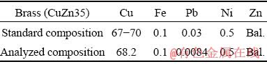
In this work, a solid/liquid continuous casting and composite technology was used to produce d8.5mm brass cladding pure copper stranded wire composite billet by using d2.12 mm �� 7 mm copper stranded wire as core and brass (CuZn35) as cladding layer, whose chemical composition is listed in Table 1. According to our previous studies, the preparing parameters were as follows: the temperature of brass melt in crucible of 1030 ��C, the temperature of brass melt in composite cavity of 1020 ��C, the casting speed of 90 mm/min, the cooling water flow rate of 400 L/h [7]. The prepared composites billet had the characteristics of good surface quality, dense cladding layer and metallurgical bonding interface, as shown in Fig. 1.
Table 1 Chemical composition of brass cladding layer (wt.%)
2.2 Drawing of composite
Brass cladding pure copper stranded wire composite billet had good surface quality and was directly drawn at room temperature to d5.2 mm composite wire at a drawing speed of 3 m/min.
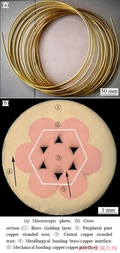
Fig. 1 Brass cladding pure copper stranded wire composite billet
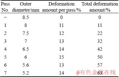
Outer diameter, deformation amount per pass and the accumulative deformation amount of the drawn composite wire are listed in Table 2.
Table 2 Drawing parameters of composite
2.3 Analysis and test methods
The cross-sectional morphology of the composite wires was observed by Nikon ECLIPSE LV150 metallographic microscope (OM). The size and area of brass cladding as well as pure copper stranded wire were measured and counted by Image-Pro Plus software. The deformation amount of the brass cladding and pure copper stranded wire were calculated under different drawing conditions. ZEISS EVO 18 scanning electron microscope (SEM) and energy dispersive spectrometer (EDS) were used to analyze the interface morphology and chemical composition of the composite wires. In order to analyze the microstructure of the composite wires during drawing, the samples were cut from the longitudinal section of the composite wires. The samples were electropolished with 100 mL H2SO4 + 600 mL H3PO4 + 100 mL H2O electrolyte. The microstructure of the samples was analyzed by electron backscatter diffraction (EBSD) scanning electron microscope. Slices with a thickness of 0.5 mm were cut along the longitudinal section of the samples and grounded to 30-50 ��m in thickness. Transmission electron microscope (TEM) samples were prepared by Gatan691 ion thinner. The microstructure of the composite wires was analyzed by G20 field emission transmission electron microscope.
The mechanical properties of the composites were tested by MTS universal material testing machine with a gauge length of 100 mm at a strain rate of 1��10-3 s-1, and three samples of each condition were tested and the average value of the properties was taken as the test result. The Vickers hardness of the brass cladding and pure copper stranded wire was measured by HXD-1000T Vickers hardness tester with a load of 50 g and loading time of 15 s. Five points were measured in each state and the average value was taken as the test result.
3 Results and discussion
3.1 Cross-sectional structure evolution of composite during drawing
Figure 2 showed the cross-sectional morphologies of the brass cladding pure copper stranded wire composites under different drawing deformation amounts. The composite billet consisted of pure copper stranded wire (consisting of six copper wires and one central copper wire) and brass cladding layer, as shown in Fig. 2(a). The interface between the peripheral pure copper stranded wire and the brass cladding layer was metallurgically bonded, and the interface among the pure copper stranded wires was mechanically bonded. There were six triangular arc gap regions, as shown in Fig. 3.
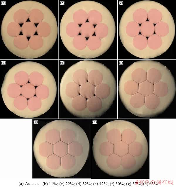
Fig. 2 Cross-sectional structure changes of composites after drawing with different deformation amounts
After drawing, with an increase of the total deformation amount, the metallurgical bonding quality of the brass/pure copper interface was still good. The plastic deformation of each pure copper wire caused the pure copper to flow into the triangular arc gap region, which reduced the volume of the triangular arc gap region. Meanwhile, the interface area between the pure copper stranded wires increased and the interface became straight, as shown in Figs. 2(b)-(e). When the total deformation amount was increased to 50%, the triangular arc gap was fully filled with pure copper, and the cross-section of the center copper wire was changed from circle to hexagon, which formed the cross-sectional structure characteristics of the metallurgical bonded circular arc brass/pure copper interface and the mechanically bonded flat pure copper/pure copper interface, as shown in Fig. 2(f). With further increasing the total deformation amount, the cross-sectional structure of the composite basically remained unchanged, as shown in Figs. 2(g) and (h).
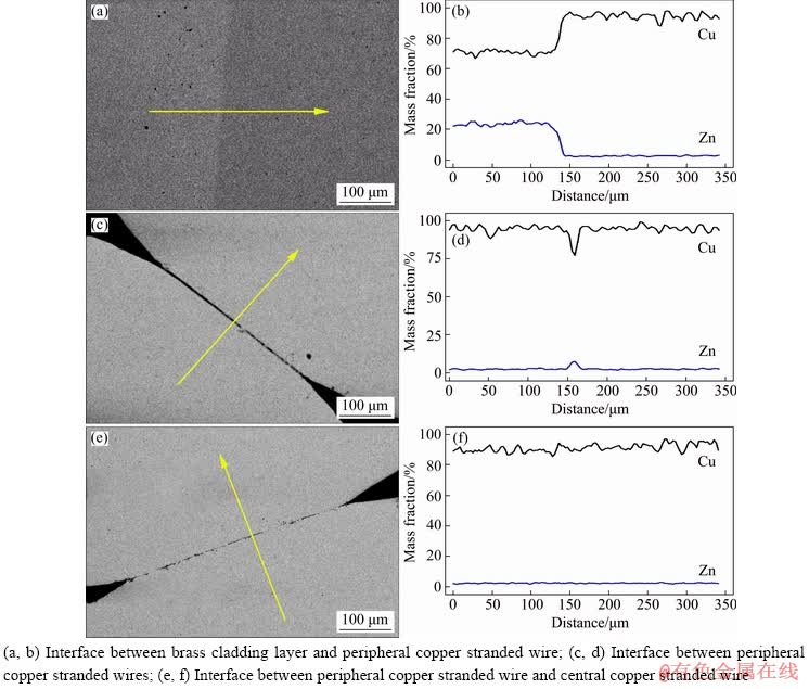
Fig. 3 SEM images showing interface morphologies (a, c, e) and EDS analyses (b, d, f) of composite billet
Figure 3 showed the SEM images and EDS composition analysis of the interface of the brass cladding pure copper stranded wire composite billet. Copper and zinc atoms diffused each other obviously on both sides of the brass/copper interface and a diffusion layer of 20-25 ��m at the interface formed, indicating the metallurgical bonding interface, as shown in Figs. 3(a and b). In addition, the copper/copper interface was of mechanically bonded state, as shown in Figs. 3(c-f). During the continuous casting, when the pure copper stranded wire contacted with the high- temperature brass melt, the copper atoms on the surface of the pure copper stranded wire and the zinc atoms in the brass melt diffused rapidly, which formed a good metallurgical bonding brass/pure copper interface with a diffusion layer containing copper and zinc atoms.
Figure 4 displayed SEM image and EDS composition analysis of the interface in the composite wire with a total deformation amount of 63%. There was a diffusion layer with a thickness of 3-5 ��m at the brass/copper interface, which indicated that the brass cladding pure copper stranded wire composite billet still had a good metallurgical bonding interface after large- deformation drawing.
In order to analyze the deformation behaviors of the brass cladding and pure copper stranded wire during drawing, the size of the brass cladding and pure copper stranded wire were statistically measured by Image-Pro Plus software. Service life of the brass cladding pure copper stranded wire composite depends on the minimum thickness of the brass cladding layer on the cross-section. The shape of the pure copper stranded wire changed during drawing. Therefore, the minimum thickness of the brass cladding layer (hereinafter called as the cladding layer thickness), the area of peripheral copper stranded wires and the area of the central copper stranded wire on the cross-section of the composite were counted (Fig. 5), and the results were shown in Fig. 6. With the increase of the total deformation amount, both the minimum thickness of the brass cladding and the area of pure copper stranded wire decreased, the outer diameter of the composite wire decreased from 8.5 to 5.2 mm, the thickness of the cladding layer decreased from 1 to 0.56 mm, the area of the peripheral copper wire and central copper wire decreased from 23.8 and 4.2 mm2 to 8.6 and 1.5 mm2, respectively. The reduction extent of the cladding layer minimum thickness of the total deformation amount 46%-63% was larger than that of the total deformation amount 0-46%.
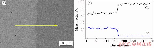
Fig. 4 SEM image showing interface morphology and EDS analysis of drawn composite with total deformation amount of 63%
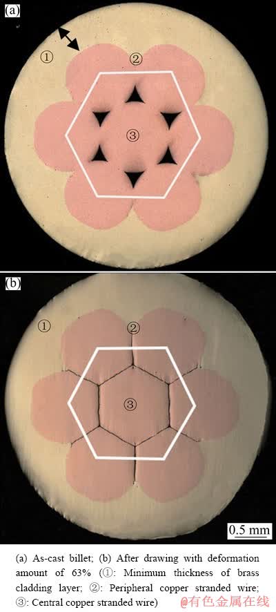
Fig. 5 Cross-sectional morphologies of composites
The cross-sectional areas of the brass cladding and pure copper stranded wire were measured by Image-Pro Plus software. The deformation amount of the brass cladding (��b) and the deformation amount of the pure copper stranded wire (��j) were calculated by
 (1)
(1)
 (2)
(2)
where  and
and  are respectively the areas of the brass cladding and the pure copper stranded wire in the composite billet, and
  and
and  are respectively the areas of the brass cladding and the pure copper stranded wire in the drawn composite wire, and the results are shown in Fig. 7. With the increase of the total deformation amount, the deformation amounts of both the brass cladding layer and pure copper stranded wire increased. When the total deformation amount was 0-42%, the deformation amount of the brass cladding layer was slightly larger than that of the pure copper stranded wire. When the total deformation amount was 42%-64%, the deformation amount of brass cladding layer was slightly smaller than that of pure copper stranded wire; however, the difference between them was small (<4%). For example, when the total deformation amount was 64%, the deformation amounts of the brass cladding layer and pure copper stranded wire were 61.0% and 64.3%, respectively. The above experimental results indicated that high synergistic deformation degree between brass cladding layer and pure copper stranded wire can be achieved during drawing of the brass cladding pure copper stranded wire composite.
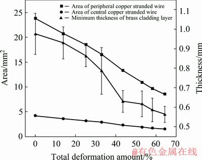
Fig. 6 Thickness of brass cladding layer and areas of peripheral copper stranded wire and central copper wire of composite during drawing
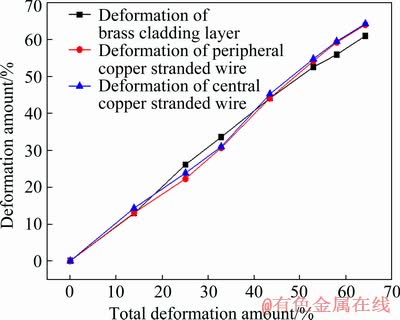
Fig. 7 Deformation amount changes of brass cladding layer, peripheral copper stranded wire and central copper stranded wire of composite with total deformation amount
During the drawing, the changes of cross- sectional structure, the areas of brass cladding layer and pure copper stranded wire were closely related to its plastic deformation [8]. The strength and work hardening rate of the brass cladding layer were significantly greater than those of the pure copper stranded wire (see Section 3.3). In general, the plastic deformation of the pure copper stranded wire was easier to happen than brass cladding layer; however, the composite billet had the cross- sectional structure characteristics of the metallurgically bonded circular arc brass/pure copper interface and the mechanically bonded flat pure copper/pure copper interface as well as six triangular arc gap regions. At the initial stage of drawing (0-46%), the pure copper stranded wire was easy to flow into the triangular arc gap region. Such flow behavior partly contributed to the total deformation caused by the reduction of the cross-sectional area of the composite, which not only induced the mechanically bonded flat interface between the pure copper stranded wires, but also decreased the reduction in the area of the pure copper stranded wire, therefore, the deformation amount of the pure copper stranded wire was slightly lower than that of the brass cladding layer. As the total deformation amount was increased to 50%, the triangular arc gap was fully filled with the pure copper stranded wire. With further increasing the total deformation amount, the composite wire exhibited deformation characteristics of dense structure composite wire, the area reduction of the pure copper stranded wire was greater than that in the initial stage of drawing, and the area reduction of the brass cladding layer was lower than that in the initial stage of drawing, which induced the larger deformation amount of the pure copper stranded wire than that of the brass cladding layer. In addition, the composite billet had the metallurgical bonding brass/copper interface and high interfacial bonding strength, which contributed to high synergistic deformation degree between brass cladding layer and pure copper stranded wire during drawing. Therefore, even after large- deformation drawing, the interface still had good metallurgical bonding quality, and the deformation amount difference between the brass cladding and pure copper stranded wire was small, which was favorable for designing structure and drawing process of the brass cladding pure copper stranded wire composite.
3.2 Microstructure evolution of composite during drawing
3.2.1 EBSD analysis
Figure 8 showed the EBSD diffraction contrast maps and orientation image maps of the longitudinal section of the composite wires, where the high angle boundary (HAB) with misorientation larger than 15�� was labeled by black bold line and the low angle boundary (LAB) with misorientation within 2��-15�� was labeled by black fine line. Figure 9 showed curves of low angle grain boundary ratios of the brass cladding and pure copper stranded wire during drawing. The microstructure of the brass cladding layer in the composite billet was columnar grains growing along the radial direction, and equiaxed grains and annealing twins formed in the pure copper stranded wire at metallurgical bonding brass/pure copper interface. During the continuous casting, when the brass melt contacted with the pure copper stranded wire, the brass melt was cooled to form a large radial temperature gradient and then solidified on the surface of the pure copper stranded wire and grew along the radial direction to form columnar grains. Meanwhile, the pure copper stranded wire was rapidly heated to high temperature by brass melt, and recrystallization and grain growth of the pure copper occurred for forming equiaxed grains. Furthermore, due to the coarse grain and high heating temperature, annealing twins formed in some coarse grains, as shown in Figs. 8(a) and (b).
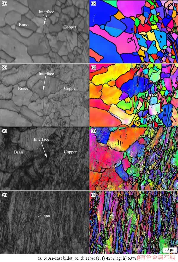
Fig. 8 EBSD diffraction contrast maps (a, c, e, g) and orientation maps (b, d, f, h) of longitudinal section of composite after drawing
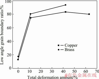
Fig. 9 Low angle grain boundary ratio changes of brass cladding layer and pure copper stranded wire of composite with total deformation amount
After drawing with a total deformation amount of 11%, the deformations of the brass cladding layer and pure copper stranded wire were small, and a small number of low angle grain boundary appeared near the brass/pure copper interface, which were respectively ~17% and 13%, with some traces strain [9] in some brass grains, as shown in Figs. 8(c) and (d). When the total deformation amount was increased to 42%, the radial columnar grains of the brass cladding layer transformed into grains close to the drawing direction and fibrous grains formed in the pure copper wire. In addition, the numbers of low angle grain boundary of the brass cladding layer and pure copper stranded wire were increased to ~93% and 83%, respectively. The strain traces in the brass grains increased obviously and crossed each other, and the strain trace contrast at grain boundaries was greater than that inside the brass grains, which indicated that the strain at grain boundaries was greater than that inside grains, as shown in Figs. 8(e) and (f). As the total deformation amount was further increased to 63%, the number of low angle grain boundary in the pure copper stranded wire decreased slightly to ~80%, as shown in Figs. 8(g) and (h). Moreover, the calibration rate of EBSD was too low to obtain accurate orientation image due to the large deformation of the brass cladding layer.
3.2.2 TEM analysis
TEM was employed to further reveal the microstructure evolution of the composites during drawing, as shown in Figs. 10-13.
Figure 10 showed the TEM images of the pure copper stranded wire in the composite. Annealing twins and a few dislocations formed in the grains, which derived from the accumulation of vacancies produced in the process that pure copper stranded wire was rapidly heated by brass melt during continuous casting of the composite billet. The brass cladding layer had uniform contrast in grain and was a typical as-cast structure, as shown in Fig. 11(a).
When the total deformation amount was 11%, a great number of dislocations formed and interacted with each other to form dislocation cells with diameter of 100-300 nm in the grains of the pure copper stranded wire, as shown in Fig. 10(b). Numerous dislocation networks also appeared in the brass cladding layer, as shown in Fig. 11(b). For the total deformation amount of 22%, the dislocation density of the pure copper stranded wire was further increased (see Fig. 11(c)), and numerous parallel planar dislocations along {111} plane formed in the brass. In addition, deformation twins with a width of 8-10 nm were observed (see Fig. 11(c)). The electron diffraction pattern of the deformation twins was analyzed to determine that the twin plane was  . As the total deformation amount was increased to 42%, the number of deformation twins with width of 3-5 nm in the brass cladding layer increased remarkably, and the twins intersected with each other, which caused a shift in the local region and serious lattice distortion, as shown in Fig. 11(d).
When the total deformation amount was 50%, some parallel strip-like microbands with width of 300-400 nm appeared in the pure copper stranded wire, with many dislocations inside microbands, as shown in Fig. 10(d). Shear bands with different orientations occurred in the brass cladding layer, intersected with each other and passed through the deformation twins, which formed intense shear bands for apparent crystal rotation in the local micro-region, as shown in Fig. 12(a). Furthermore, high-density dislocation piling-up regions were observed at the intersection of the shear bands (see Fig. 12(b)), indicating high strain state at the intersection of the shear bands.
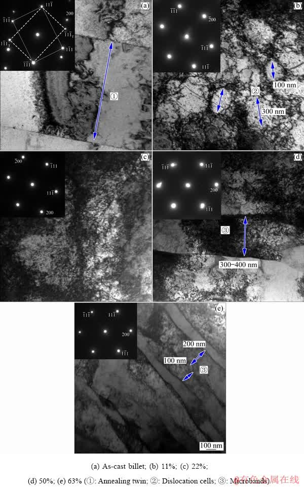
Fig. 10 TEM images of pure copper stranded wire of composite after drawing
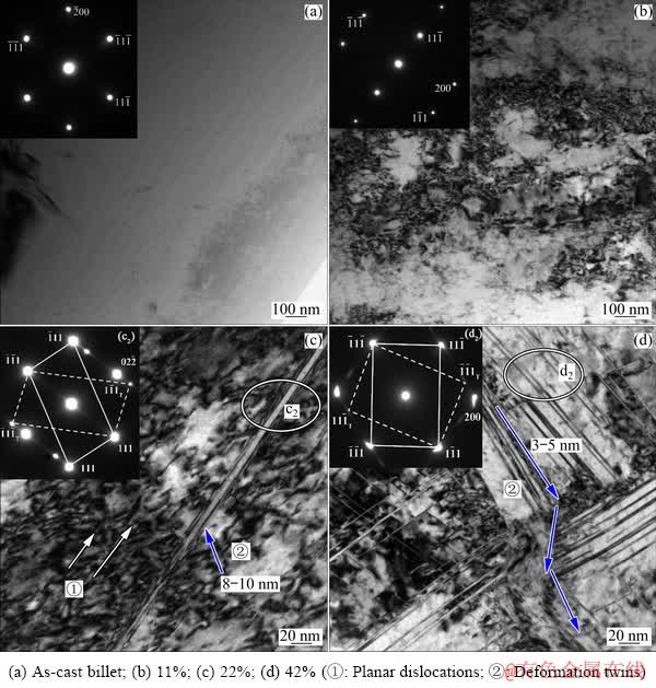
Fig. 11 TEM images of brass cladding layer of composite after drawing
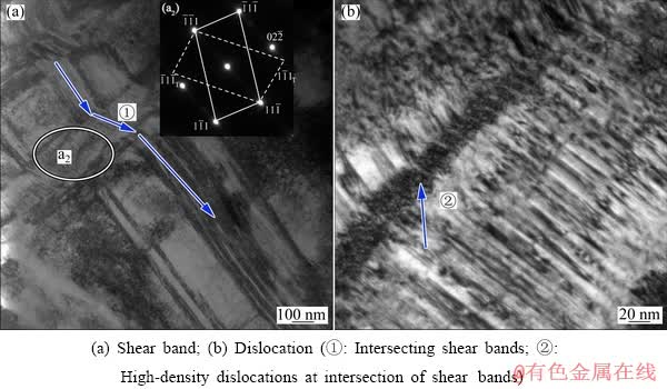
Fig. 12 TEM images of brass cladding layer of composite after drawing with total deformation amount of 50%
As the total deformation amount rose to 63%, the number of microbands with the width of 100-200 nm in the pure copper stranded wire increased and the dislocation number inside the grains decreased slightly, as shown in Fig. 10(e). The number of dislocation and deformation twin in the brass cladding layer increased obviously, and the twin width fell to 2-4 nm, as shown in Fig. 13(a). In addition, the shear bands interacted more intensively, and secondary twins and high-density dislocations were found in the large primary twins. Intensive interaction between secondary twins and dislocations happened in the brass cladding layer with high strain state, as shown in Figs. 13(b) and (c).
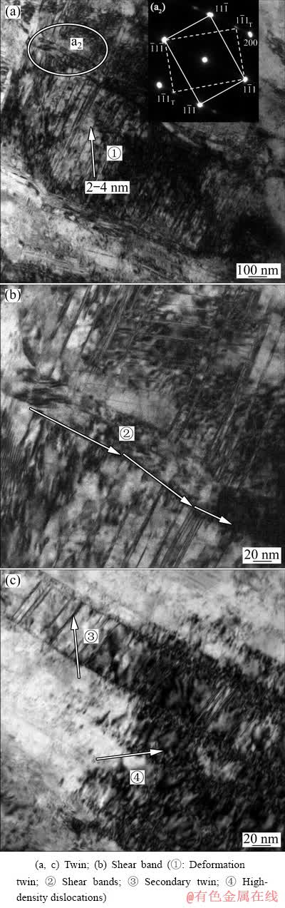
Fig. 13 TEM images of brass cladding layer of composite after drawing with total deformation amount of 63%
According to the microstructure analysis mentioned above, during the drawing, with an increase of the total deformation amount, the microstructure evolution of the brass cladding layer was successively planar dislocation, twin, shear band etc., and the microstructure evolution of the pure copper stranded wire was successively dislocation entanglement, dislocation cell, parallel microband etc. The microstructure difference between the brass cladding layer and pure copper stranded wire was large [10,11]. Pure copper has high stacking fault energy, dislocations of different slip systems were activated during drawing, cross slip of dislocation was easy to occur, and the dislocations of different slip systems were entangled, reacted and annihilated with each other under the action of external stress, which formed numerous dislocation cells. With the increase of the total deformation amount, on one hand, the primary grains were elongated to form the fibrous structure by the principal stress in the drawing direction; on the other hand, the shear strain increased, which led to the uneven deformation in the cellular structure and the formation of the microbands [12]. Furthermore, for the deformation amount of 57%, both the brass cladding layer and pure copper stranded wire had the relatively high hardening state, the strain stored energy of the pure copper stranded wire rose significantly, and the critical temperature of dynamic recovery reduced. Moreover, the diameter of the pure copper wire reduced with an increase of the total deformation amount, taking the d1.32-1.36 mm wires for example, a large heat which was produced during drawing induced temperature rise of the pure copper stranded wire or even more than the critical temperature of dynamic recovery, which was responsible for the reductions of dislocation number and low angle grain boundary number in the pure copper stranded wire. The main deformation mechanism of the pure copper stranded wire during drawing was dislocation slip [13-15].
Brass has low stacking fault energy, and the dislocations produced during drawing were easily decomposed into extended dislocations instead of cross slip, which tended to form planar dislocations with low mobility. With the increase of the total deformation amount (>22%), a large number of planar dislocations were formed and entangled, which resulted in stress concentration in the microregion. When the stress exceeded the critical stress to activate twin, the deformation twin formed. With further increasing the total deformation amount, shearing strain increased and numerous twins with different orientations formed. The twins were intersected and interacted with dislocations, which even formed the secondary twins, contributing to serious lattice distortion. With an increase of the total deformation amount, therefore, the main deformation mechanisms of the brass cladding layer were successively dislocation plane slip, twinning and shear deformation [16-20].
3.3 Mechanical property evolution of composite during drawing
The structure of the brass cladding pure copper stranded wire composite was very complicated. In order to analyze the mechanical property evolution of the composite during the drawing, the hardness values of the brass cladding layer, peripheral copper wire and central copper wire under different drawing conditions were tested. The results were shown in Fig. 14.
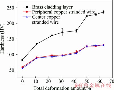
Fig. 14 Hardness values of brass cladding layer, peripheral copper stranded wire and central copper stranded wire of composite after drawing at different deformation amounts
From Fig. 14, with an increase of the total deformation amount, the hardness of the brass cladding layer and the pure copper stranded wire increased, both the hardness and the work hardening rate of the brass cladding layer were higher than those of the pure copper stranded wire, and the hardness difference between them also increased. In addition, the hardness changes of both the brass cladding layer and pure copper stranded wire with the total deformation amount were similar, which can be divided into three parts. When the total deformation amount was 0-11%, the hardness of brass cladding layer and pure copper stranded wire increased evidently, with a high work hardening rate. The hardness increased from HV 82 and HV 60 of the composite billet to HV 133 and HV 90, respectively. When the total deformation amount was 11%-42%, the hardness increase of the brass cladding and pure copper stranded wire fell, and their hardness values were respectively HV 176 and HV 105 when the total deformation amount was 42%. When the total deformation amount was further increased (42%-63%), the hardness increase of both the brass cladding and pure copper stranded wire rose, and the work hardening rate also increased. For the total deformation amount of 63%, the hardness values of the brass cladding layer and pure copper stranded wire were HV 236 and HV 130, respectively.
Figure 15 showed the tensile strength and elongation to failure of the composite after drawing with different deformation amounts. The tensile strength and elongation of the composite billet were 240 MPa and 53.1%, respectively. With the increase of the total deformation amount, the tensile strength of the composite increased while the elongation decreased. When the total deformation amounts were 11% and 23%, the tensile strength increased to 295 and 351 MPa, and the elongation fell to 23.8% and 6.1%, respectively. With further increasing the total deformation amount, the tensile strength increased linearly and the elongation declined slowly. The tensile strength rose to 519 MPa and the elongation dropped to 3.2% when the total deformation amount was 63%.
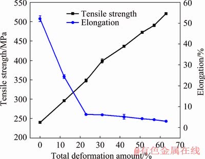
Fig. 15 Tensile strength and elongation to failure of composite after drawing at different total deformation amounts
The mechanical property evolution of the brass cladding pure copper stranded wire composite during drawing was closely relevant to its deformation behavior and microstructure [20,21]. When the total deformation amount was small (0-11%), the number of dislocation in the brass cladding layer and pure copper stranded wire rose significantly, and numerous dislocation cells formed in the pure copper stranded wire, which increased the hardness and strength of the brass cladding layer and pure copper stranded wire, improved the work hardening rate and reduced the elongation to failure remarkably. When the total deformation amount increased (11%-42%), on one hand, the dislocation density of the pure copper stranded wire continued to increase, the number of planar dislocation in the brass cladding layer also increased and nano-scale deformation twins formed, which resulted in the continuous increase of the hardness of the brass cladding layer and pure copper stranded wire. On the other hand, there were six triangular arc gap regions among the pure copper stranded wires, the pure copper wire flowed to the triangular arc gap region during drawing, meanwhile, the metallurgical bonding interface between the brass and pure copper was achieved, and the deformation of the brass cladding layer was affected by the rheological behavior of pure copper wire, which was beneficial to reducing the work hardening rates of the pure copper stranded wire and brass cladding layer. The combined action of the above two factors were responsible for that the hardness increase of the brass cladding layer and pure copper stranded wire decreased with an increase of the total deformation amount. When the total deformation amount was further increased (42%-63%), the triangular arc gap was fully filled with pure copper wire, stripe-like microbands formed and the density of dislocation increased obviously in the pure copper stranded wire. Meanwhile, both the dislocation number and twin number in the brass cladding layer also increased remarkably, twins intersected and interacted with dislocation. Such behaviours contributed to the increase of hardness and strength of the brass cladding layer and pure copper stranded wire, the work hardening rate enhanced and the elongation to failure reduced, with an increase of the total deformation amount.
According to the above experimental results and analysis, the brass cladding copper stranded wire composite billet prepared by solid/liquid continuous casting and composite technology had good surface quality and can be directly drawn without surface treatment. In addition, the composite billet had metallurgical bonding brass/pure copper interface with an elongation to failure of 53.1%, and the synergistic deformation degree between the copper stranded wire and brass cladding layer was high during drawing, which had good drawing workability. Based on the above advantages, a novel process of solid/liquid continuous casting and composite forming��cold drawing was proposed to produce super-long brass cladding pure copper stranded wire composite with seamless cladding layer and metallurgical bonding interface. This process had the advantages of small equipment investment, short process flow, low energy consumption and low production cost, etc.
4 Conclusions
(1) The brass cladding pure copper stranded wire composite billet prepared by solid/liquid continuous casting and composite technology had good surface quality and metallurgical bonding brass/pure copper interface as well as the elongation of 53.1%. The composite billet can be drawn directly without surface treatment. During drawing, the deformation amount difference between the brass cladding layer and pure copper wire was small (<4%), with high synergistic deformation degree between them, and the cumulative cold deformation amount reached 63%, which indicated that the composite billet had good drawing workability.
(2) With the increase of the total deformation amount, the plastic deformation of pure copper wire caused the pure copper to flow into the triangular arc gap among copper wires, and the copper/copper interface area increased and the interface became straight. When the total deformation amount was 50%, the cross-section of the center copper wire was changed from circle to hexagon, which formed the cross-sectional structure characteristics of the metallurgical bonded circular arc brass/pure copper interface and the mechanically bonded flat pure copper/pure copper interface
(3) With increasing the total deformation amount from 11% to 63%, dislocation cells and microbands formed in the pure copper wire and the main deformation mechanism was dislocation slip. In the brass cladding layer, planar dislocation net, intersecting twins and shear bands formed successively, and the main deformation mechanisms were the dislocation plane slip, twinning and shear deformation, respectively.
(4) When the total deformation amount was 0-11%, the hardness values of the brass cladding layer and pure copper wire increased from HV 82 and HV 60 to HV 133 and HV 90, respectively, with high work hardening rate. For the total deformation amount of 11%-42%, the hardness increase of them reduced due to flowing of pure copper into the triangular arc gap. With further increasing the total deformation amount, the hardness increase of them increased due to the increase of both dislocation and twin, which were respectively HV 236 and HV 130 at the total deformation amount of 63%.
(5) With the increase of the total deformation amount, the tensile strength of the composite increased linearly while the elongation decreased. For the total deformation amount of 63%, the tensile strength of the billet increased from 240 to 519 MPa, but the elongation decreased from 53.1% to 3.2%.
(6) The process of solid/liquid continuous casting and composite forming��drawing can work as a novel compact method to produce high-quality brass cladding pure copper stranded wire composite as railway grounding wire.
References
[1] LI Kun, LU Yao-hua, WANG Jun-fei. Railway through grounding wire development trend [J]. Railway Quality Control, 2006(12): 14-1534. (in Chinese)
[2] HU Hui-zhong. Performance analysis and application of new grounding material for railway [J]. Railway Signal Communicate Engineering, 2012, 9(6): 70-74. (in Chinese)
[3] HAN Zhi-dong, WANG Cai-sheng. Performance analysis of environmentally friendly grounding wire [J]. Electric Engineering, 2011(11): 10-11. (in Chinese)
[4] HUAI Ping. Railway through ground system [J]. China Railway, 2014(4): 88-90. (in Chinese)
[5] JIANG Yan-bin, XIE Jian-xin, LING Liang. A kind of forming equipment and process method for metal-clad material solid/liquid continuous casting and composite, China Patent,106111931A[P]. 2016-11-16. (in Chinese)
[6] MEI Jun, LIU Xin-hua, JIANG Yan-bin, CHEN Song, XIE Jian-xin. Liquid-solid interface control of BFe10-1-1 cupronickel alloy tubes during HCCM horizontal continuous casting and its effect on the microstructure and properties [J]. International Journal of Minerals Metallurgy and Materials, 2013, 20(8): 748-758.
[7] JIANG Yan-bin, LING Liang, XIE Jian-xin. Influences of preparing parameters on surface quality and interface bonding state of brass cladding copper stranded wire by inversion solidification [J]. The Chinese Journal of Nonferrous Metals, 2018, 28(4): 693-704. (in Chinese)
[8] ZHANG Jun-lin. Fundamentals of materials science [M]. Beijing: Chemical Industry Press, 2006. (in Chinese)
[9] DUGGAN B J, HATHERLY M, HUTCHINSON W B, ET A L. Deformation structures and textures in cold-rolled 70:30 brass[J]. Metal Science, 1978, 12(8): 343-351.
[10] HONG S I, LAIRD C. Mechanisms of slip mode modification in F.C.C. solid solutions [J]. Acta Metallurgica et Materialia, 1990, 38(8): 1581-1594.
[11] HAMDI F, ASGARI S. Influence of stacking fault energy and short-range ordering on dynamic recovery and work hardening behavior of copper alloys [J]. Scripta Materialia, 2010, 62(9): 693-696.
[12] YANG Yang. The principal of metal plastic processing [M]. 1st ed. Beijing: Chemical Industry Press, 2016. (in Chinese)
[13] KUO C M, LIN C S. Static recovery activation energy of pure copper at room temperature [J]. Scripta Materialia, 2007, 57(8): 667-670.
[14] GAO K, LIU M, ZOU F, ET A L. Characterization of microstructure evolution after severe plastic deformation of pure copper with continuous columnar crystals [J]. Materials Science and Engineering A, 2010, 527(18-19): 4750-4757.
[15] MALIN A S, HATHERLY M. Microstructure of cold-rolled copper [J]. Metal Science, 1979, 13(8): 463-472.
[16] ASGARI S, EL-DANAF E, KALIDINDI S R, DOHERTY R D. Strain hardening regimes and microstructural evolution during large strain compression of low stacking fault energy fcc alloys that form deformation twins [J]. Metallurgical and Materials Transactions A, 1997, 28(9): 1781-1795.
[17] EL-DANAF E, KALIDINDI S R, DOHERTY R D. Influence of grain size and stacking-fault energy on deformation twinning in FCC metals [J]. Metallurgical and Materials Transactions A, 1999, 30(5): 1223-1233.
[18] BAHMANPOUR H, YOUSSEF K M, HORKY J, ET A L. Deformation twins and related softening behavior in nanocrystalline Cu-30%Zn alloy [J]. Acta Materialia, 2012, 60(8): 3340-3349.
[19] JIANG Shuang, PENG Ru-lin, JIA Nan, ZHAO Xiang, ZUO Liang. Microstructural and textural evolutions in multilayered Ti/Cu composites processed by accumulative roll bonding [J]. Journal of Materials Science & Technology, 2019, 35(6): 1165-1174.
[20] YAN Hai-le, ZHAO Xiang, JIA Nan, ZHENG Yi-ran, HE Tong. Influence of shear banding on the formation of brass-type textures in polycrystalline fcc metals with low stacking fault energy [J]. Journal of Materials Science & Technology, 2014, 30(4): 408-416.
[21] HATHERLY M, MALIN A S. Shear bands in deformed metals [J]. Scripta Metallurgica, 1984, 18(5): 449-454.
[22] SAKHAROVA N A, FERNANDES J V, VIEIRA M F. Strain path and work-hardening behavior of brass [J]. Materials Science and Engineering A, 2009, 507(1-2): 13-21.
��ͭ����ͭ���߸��ϲ������ι����к����ṹ������֯����ѧ���ܱ仯
�����1,2������˧2���� ��2��л����2,3
1. ���ϴ�ѧ ���Ͽ�ѧ�빤��ѧԺ����ɳ 410083��
2. �����Ƽ���ѧ �����Ƚ��Ʊ������������ص�ʵ���ң����� 100083��
3. �����Ƽ���ѧ �ִ���ͨ����������ӹ���������ʵ���ң����� 100083
ժ Ҫ���Բ��ù�/Һ�������ϳ��ι����Ʊ����⾶8.5 mm��ͭ������ͭ���߸������������μӹ����о����ι����и��ϲ��Ϻ����ṹ����֯����ѧ���ܵı仯��������λ��ơ�����������������������õı���������ұ���ϵĻ�ͭ/��ͭ���棬�Ϻ��쳤�ʴﵽ53.1%�����ι����У���ͭ�������ͭ�������Эͬ���γ̶Ƚϸߡ������ܱ�����������ͭ���߷������Ա����������ͭ��֮�乹�ɵ����ǻ��μ�϶�������ܱ�����������50%ʱ�����ǻ��μ�϶������ͭ�����������ܱ�����������63%����ͭ�����ڲ��Ⱥ����λ��������״��������֯����ͭ�������ڲ��Ⱥ��γ�ƽ��λ�������������α��Ͼ����б������Ҫ���λ�������Ϊλ��ƽ�滬�ơ��α������ͼ��б��λ��ơ����ϲ��ϵĿ���ǿ������̬��240 MPa�����ܱ�����63%��519 MPa�����Ϻ��쳤������̬��53.1%���͵�3.2%������/Һ�������ϳ��Ρ����Ρ������̼ӹ��������������Ʊ�������·��ͨ�����û�ͭ������ͭ���߸��ϲ��ϡ�
�ؼ��ʣ���/Һ�����������߲ģ����Σ�����֯�ݱ䣻��ѧ����
(Edited by Xiang-qun LI)
Foundation item: Project (51104016) supported by the National Natural Science Foundation of China; Project (51925401) supported by the National Natural Science Foundation for Distinguished Young Scholars of China; Project (2019B10087) supported by Ningbo Science and Technology Innovation 2025 Major Project, China
Corresponding author: Jian-xin XIE; E-mail: jxxie@mater.ustb.edu.cn
DOI: 10.1016/S1003-6326(20)65345-6
Abstract: A solid/liquid continuous casting and composite technology was used to produce d8.5 mm brass cladding pure copper stranded wire composite billet and the composite billet was then drawn. The results showed that the composite billet had good surface quality, metallurgical bonding interface between brass and pure copper as well as elongation of 53.1%. Synergistic deformation degree between pure copper wire and brass cladding layer was high during drawing. With an increase of the total deformation amount, the plastic deformation of the pure copper wire reduced triangular arc gaps between the pure copper wires and the triangular arc gaps were fully filled at 50%. When the total deformation amount was increased to 63%, dislocation cells and microbands successively formed in the pure copper wire. In the brass cladding layer, planar dislocation networks, twins and shear bands formed successively, and the main deformation mechanisms were dislocation sliding, twinning and shear deformation. The tensile strength increased from 240 MPa of the composite billet to 519 MPa of the one with the deformation amount of 63%, but the elongation decreased from 53.1% to 3.2%. A process of solid/liquid continuous casting and composite forming��drawing can work as a new compact method to produce brass cladding pure copper stranded wire composite as railway through grounding wire.
