
Trans. Nonferrous Met. Soc. China 23(2013) 1039-1045
Effect of pretreatment on electrochemical etching behavior of Al foil in HCl-H2SO4
Chao-lei BAN1,2, Ye-dong HE2, Xin SHAO1, Juan DU1
1. School of Materials Science and Engineering, Liaocheng University, Liaocheng 252059, China;
2. Beijing Key Laboratory for Corrosion, Erosion and Surface Technology, University of Science and Technology Beijing, Beijing 100083, China
Received 1 February 2012; accepted 19 June 2012
Abstract:
The aluminum foil for high voltage aluminum electrolytic capacitor was immersed in 0.5 mol/L H3PO4 or 0.125 mol/L NaOH solution at 40 ��C for different time and then DC electro-etched in 1 mol/L HCl+2.5 mol/L H2SO4 electrolyte at 80 ��C. The pitting potential and self corrosion potential of Al foil were measured with polarization curves (PC). The potentiostatic current��time curve was recorded and the surface and cross section images of etched Al foil were observed with SEM. The electrochemical impedance spectroscopy (EIS) of etched Al foil and potential transient curves (PTC) during initial etching stage were measured. The results show the chemical pretreatments can activate Al foil surface, facilitate the absorption, diffusion and migration of Cl- onto the Al foil during etching, and improve the initiation rate of meta-stable pits and density of stable pits and tunnels, leading to much increase in the real surface area and special capacitance of etched Al foil.
Key words:
Al foil; polarization; pitting corrosion; electrochemical etching; Al electrolytic capacitor;
1 Introduction
Aluminum electrolytic capacitor is one of the key components in electric appliances and is widely used in energy storage and conversion, liquid crystal display fabrication, and integrated circuit process [1]. In order to satisfy the high integration requirements of electronic equipments, aluminum electrolytic capacitor is developing towards smaller volume, higher capacitance and lower cost. The electric capacitance(C) of aluminum electrolytic capacitors can be expressed by the following formula of C=��o ��r S/d, where ��o is the vacuum dielectric constant, ��r is the relative dielectric constant of the anodic oxide film, S is the effective surface area of aluminum foil electrode, and d is the film thickness. Although formation of high dielectric constant composite oxide films such as Al2O3-(TiO2, BaTiO3, ZrO2, Ta2O5, Nb2O5) is focused on now [2,3], the industrial application of such composite films has not been found due to their high dielectric loss. Meanwhile, working voltage determines the pure aluminum oxide film thickness (1.0-1.4 nm/V) and its ��r is almost fixed (about 8.4-10 for amorphous Al2O3 or ��-Al2O3). The enlargement of the aluminum electrode surface area by electrochemical etching is still the most important method.
DC etching has been performed to obtain a tunnel-type etching in acid solution morphology in aluminum foils for high-voltage capacitors. In general, the DC electrochemical etching process consists of three steps: pretreatment, tunnel formation in length and distribution and tunnel widening in diameter [4,5]. Many researchers have studied the effects of the components and structures of pure Al foils, acid concentration, temperature, and current parameters on tunnel formation and tunnel widening [6]. The addition of trace inert metals such as Pb, Ag, Sn, In, Mg, Cu in Al foil can promote tunnel formation [7-9]. However, remnant inert metals in the subsequent anodic oxide film will deteriorate the property of capacitor. Control of pitting and tunnel sites, density and distribution on Al foil for Al electrolytic capacitors using patterned masks is popular now [10,11]. But it is difficult to obtain such masks with an ideal ordered array of holes.
Chemical pretreatments in HCl, H2SiF6, H2SO4, H3PO4, etc., have been widely adopted in aluminum etching industries to obtain an even distribution of high-density tunnels and increase the specific internal area of etched foil [12], but the etching characteristics according to the pretreatment have not been clarified sufficiently yet. In this work, H3PO4 and NaOH were selected as pretreatment solutions. The effects of chemical pretreatment of aluminum foil on the pit nucleation and electrostatic capacitance were investigated, in addition to the analysis of the relationship between the pretreatment conditions and the pitting/etching type by the current��time curves in potentiostatic test, the initial potential transients and EIS during the electrochemical etching of Al foil. The results can help to elucidate the effects of chemical pretreatment on pitting behavior of Al foil.
2 Experimental
2.1 Specimen
The specimens in this experiment were commercial aluminum foils for high voltage electrolytic capacitors, with 99.99% in purity, 95% in (100) cubicity and 110 ��m in thickness.
2.2 Pretreatment
Before etching, these specimens were immersed in 0.5 mol/L H3PO4 at 40 ��C for 30 s, 1 min and 3 min, respectively, or immersed in 0.125 mol/L NaOH at 40 ��C for 15 s, 30 s and 1 min, respectively. Some specimens were rinsed with deionized water as blank samples. All solutions used in this work were prepared from reagent grade chemicals and deionized water.
2.3 Polarization curves and AC impedance spectroscopy
After pretreatments, the specimen with the exposed area of 1 cm��1 cm was rinsed with deionized water, then quickly transferred to 1 mol/L HCl+2.5 mol/L H2SO4 at 80 ��C as working electrode, in which polarization curves and potentiostatic current��time curves were measured with CHI electrochemical measure system. A Pt foil electrode was used as counter electrode. A reference electrode (Hg, Hg2Cl2|saturated KCl) was placed in a fixed position beside the sample. During polarization curve measurement, the scan rate was 10 mV/s. After the following DC-etching, the AC impedance spectroscopy of etched Al foil was measured with the same set as a function of frequency in the range from 10 mHz to 100 kHz.
2.4 DC-etching and potential transient analysis
After pretreatments, the specimens with the area of 5.2 cm��13 cm was rinsed with deionized water, then used as anode and mounted on a sample holder with the area of 5 cm��9 cm exposed to the 80 ��C 1 mol/L HCl+2.5 mol/L H2SO4 etching solution. Two graphite electrode plates of 15.5 cm��6.5 cm��8 cm were used as counter cathodes, with a gap of 25 mm between them. The specimen was placed parallel to the two electrode plates with a distance of 10 mm between each of them. Temperature of the solution was measured by alcohol thermometer and controlled by heating blender and temperature controller. Direct current etching was carried out immediately after placing the sample holder into the electrolyte. A constant current density of 150 mA/cm2 was applied for 150 s. At initial stage of etching, the change in the cell voltage between anode and one counter cathode with time (Ec vs t) was monitored and recorded by a digital multimeter connected to a PC system for potential transient analysis. The etched foil was anodized at 90 ��C in 150 g/L C6H16N2O4 for producing the anodic oxide film as dielectric layer by applying 100 V for 10 min and the special capacitance of the film was measured with a LCR meter in 150 g/L C6H16N2O4 at 30 ��C.
2.5 Etched morphology observation
After electrochemical etching, the sample was rinsed thoroughly with deionized water and dried under ambient condition. For surface morphology studies, the sample was examined under a scanning electron microscope (SEM, LEO 435VP). For sectional observation, which would shed light on tunnel development, the etched samples were anodized, mounted vertically in epoxy resin, mechanically polished, chemically dissolved in iodine methanol solution (10%I2/CH3OH), sputter-coated with gold and examined by SEM.
3 Results and discussion
3.1 Polarization curves
Figure 1 shows the polarization curves in 1 mol/L HCl+2.5 mol/L H2SO4 at 80 ��C for samples pretreated in 0.5 mol/L H3PO4 or 0.125 mol/L NaOH solution at 40 ��C for different time, respectively. The polarization curves indicated that the pitting potential of the as-received specimen without pretreatment was around -800 mV vs SCE and lightly shifted to the cathodic direction with increasing pretreatment time in H3PO4 or NaOH solution. This suggests that the Al foil surface becomes more vulnerable following H3PO4 or NaOH pretreatment due to the thinning of the protective oxide layer. Furthermore, the free corrosion potential shifted to a more cathodic direction after the pretreatment in NaOH (Fig. 1(b)), compared with H3PO4 solution (Fig. 1(a)). This indicated an increased dissolution on the entire surface and almost complete removal of the protective oxide layer in the NaOH solution.

Fig. 1 Effect of pretreatments on polarization curves of Al foils in 1 mol/L HCl+2.5 mol/L H2SO4 at 80 ��C
When the potential is above -800 mV (SCE), all curves become steep suddenly and limiting current densities appear because the growth of stable pits is controlled by diffusion of solution in pits and concentration polarization predominates the process. Free corrosion potentials, pitting potentials and limiting current densities of samples pre-treated for longer time are the same as the No. 4 sample, which are not drawn in Fig. 1.
3.2 Current��time curves and metastable pits morphologies
Figure 2 shows potentiostatic current��time curves and corresponding metastable pits morphologies for differently pretreated samples, which are measured in 1 mol/L HCl+2.5 mol/L H2SO4 solution at 80 ��C for 120 s under constant potential no less than pitting potential. Compared with blank samples (Figs. 2(a) and (a��)), it can be seen that H3PO4 pretreatment (Figs. 2(b) and (b��)) or NaOH pretreatment (Figs. 2(c) and (c��)) makes current fluctuate more frequently, which results in more observable metastable pits on samples surface. Furthermore, under the same pitting potential (-900 mV), current fluctuates more frequently and more metastable pits appear on sample surface after NaOH pretreatment than H3PO4 pretreatment.
Many researchers have reported current fluctuations in potentiostatic or potentiodynamic test under the pitting potential. They attributed the current fluctuations to appearance of metastable pits [13,14]. Generally, metastable pits are pits which nucleate and grow in very short time before passivation. ISAACS indicated that troughs on current fluctuation curves resulted from anodic growth of pits and wave crests were due to reduction of oxygen [15]. Pit initiation occurs by chloride-assisted localized dissolution at the oxide/metal interface [16]. H3PO4 or NaOH pretreatment has thinned the oxide film before etching and more Cl- can easily penetrate through it and improve the nucleation ratio of metastable pits during etching.
3.3 Surface and cross section morphologies of etched Al foil
Figures 3(a)-(f) shows the etched pit surface morphologies formed by the electrochemical etching of Al foil in 1 mol/L HCl+2.5 mol/L H2SO4 at 80 ��C for 150 s with 150 mA/cm2 after different pretreatments. It is found that there are noticeable differences in the morphologies of etch pits, depending on the pretreatments. For the blank specimen (Figs. 3(a) and (d)), the size of the etch pits is large, and the density of etch pits is low. Compared to the blank specimen, the H3PO4 or NaOH pretreatment induced a high density of pits (Figs. 3(b) and (e), Figs. 3(c) and (f)) because the meta-stable pits shown in Fig. 2 acted as pit initiation sites during the etching process. The average pit size decreased because the high density of pits had to supply the same amount of applied current.
Figures 3(g)-(i) show the cross-sections of the anodic oxide replicas with the substrate aluminum selectively dissolved, in which the shape and array of etch tunnels developing along <100> directions are observed. It is found that the morphological characteristics according to the pretreatments are consistent with those obtained from Figs. 3(a)-(f). For blank specimens, the adsorption and diffusion of Cl- onto the surface during etching is considered to bring about active and successive dissolutions particularly concentrated on the weak points in the oxide film, leading to the fact that the etch pit not only forms relatively large, but also is non-uniformly distributed.
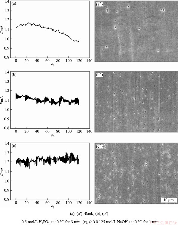
Fig. 2 Potentiostatic current��time curves under constant potentials of -870 mV (a), -900 mV (b, c) in 1 mol/L HCl+2.5 mol/L H2SO4 at 80 ��C and corresponding meta-stable pits morphologies (a��, b��, c��) for differently pretreated samples
However, H3PO4 or NaOH pretreatment makes the Al foil surface oxide film dissolve and become thin, which facilitates the adsorption, diffusion and electro-migration of Cl- onto the surface during etching, resulting in high density of formation with etch tunnels. Maybe the NaOH pretreatment affects the oxide��s dissolution more seriously than H3PO4 pretreatment, therefore, the higher density of pits, tunnels and corresponding specific surface area can be expected from the NaOH pretreatment, as proved by Fig. 2(c��) and Figs. 3(c), (f), (j).

Fig. 3 Morphologies of etched Al foil surface (a-f) and cross section (g-i) with different pretreatments
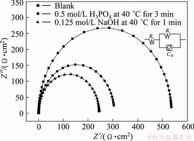
Fig. 4 Effect of pretreatment on electrochemical impedance spectra of etched Al foil
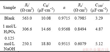
Table 1 Circuit parameters from EIS data and special capacitance (C100) of 100 V formation voltage
3.4 AC impedance characterization
Figure 4 shows the effect of pretreatment on electrochemical impedance spectra of etched Al foil, in which the measured impedance spectra are plotted into Nyquist diagram for the etched specimens after different pretreatments for comparison. The electrochemical phenomena and interface reaction process are analyzed by fitting the equivalent circuit model in inserted figure in Fig. 4, where Q is constant phase element (CPE), Rt indicates the charge transfer resistance, Rs is the solution resistance and Cdl is the capacitance of the electrical double layer of Q, which is proportional to the specific surface area. The impedance behavior can be represented as constant phase element (CPE) including �� (frequency dispersion factor) and displayed in Eq. (1), where C=(��o ��r S)/d and ��=2��f. In Eq.(1), if ��=0, 1, -1 or 0.5, then ZCPE can be expressed as resistance R, capacitance C, inductance L�� and Warburg-impedance W/(i��)1/2, respectively. Table 1 lists the circuit parameters evaluated from the equivalent circuit model. The special capacitance (C100) of anodic oxide film of 100 V formation voltage is also listed in Table 1.
 -1�ܦ���1,
  (1)
(1)
Rt values for etched foils pretreated in blank solution, in 1 mol/L H3PO4, and 0.125 mol/L NaOH represent 563, 306.6 and 250.1 ����cm2, respectively, showing a tendency to decrease. But on the contrary, Cdl values increase to 10.08, 14.66 and 18.80 ��F/cm2, in consistent with the change of C100 and ��, in which the surface roughness values of etched foil reduce to 0.9715, 0.9568, 0.9515 in the same sequence of the solutions as above. Thus, it is suggested that for 0.125 mol/L NaOH pretreatment, the high specific surface area is generated, which gives rise to decreasing in both Rt and �� and increasing in Cdl and C100.
3.5 Potential transient analysis
Figure 5 shows the initial potential (cell voltage minus solution resistance voltage) transients obtained at an etching current of 150 mA/cm2 in 1 mol/L HCl+2.5 mol/L H2SO4 at 80 ��C after pretreatment in 0.5 mol/L H3PO4 at 40 ��C for 3 min or 0.125 mol/L NaOH at 40 ��C for 1 min. Following the sharp increase of potential induced by the ohmic drop (Eocp), the potential increases slowly to the peak potential, Epp, due to the formation of the anodic oxide film on the surface. With H3PO4 or NaOH solution pretreatment, the initial potential rise from Eocp to Epp (��Emax=Epp-Eocp) decreases and the potential increase rate to Epp decreases slowly. Since the potential increase rate is commensurate with the film growth rate of 1.4 nm/V [17], the rate of film formation decreases from 23 nm/s in blank solution to 6 nm/s in 0.125 mol/L NaOH, and the maximum attainable oxide thickness also decreases. The potential decay from Epp to Ea is associated with the breakdown of the anodic oxide film, and the decay (��D =��a-��p) becomes fast with H3PO4 or NaOH solution pretreatment. The natural oxide layer on the Al foil surface maybe acts as seed for growth of the anodic oxide film in the initial etching stage. H3PO4 or NaOH pretreatment dissolves such seeds greatly and the film formation rate becomes slow and easy to break down with etching.
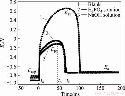
Fig. 5 Effect of pretreatment on initial potential transient during etching in 1 mol/L HCl+2.5 mol/L H2SO4
4 Conclusions
1) The pretreatment by H3PO4 or NaOH solution before electro-etching can dissolve oxide film on Al foils surface and make Al foil more vulnerable to Cl- so as to increase the nucleation and initiation ratio of meta-stable pits and density of stable pits and tunnels.
2) NaOH solution pretreatment is superior to H3PO4 solution pretreatment in increasing distribution of etch pits and tunnels for the Al foil, which causes more increase in the specific internal surface area and special capacitance of etched foil.
References
[1] BAN Chao-lei, HE Ye-dong, SHAO Xin. Effect of citric acid on microstructure and electrochemical characteristics of high voltage anodized alumina film formed on etched Al foils [J]. Transactions of Nonferrous Metals Society of China, 2011, 21(1): 133-138.
[2] BU Jun-fu, SUN Lan, WU Qi, WANG Meng-ye, LIN Chang-jian. Al2O3-TiO2 composite oxide films on etched aluminum foil fabricated by electrodeposition and anodization [J]. Science China Chemistry, 2011, 54(10): 1558-1564.
[3] DU Xian-feng, XU You-long. Formation of Al2O3-BaTiO3 nanocomposite oxide films on etched aluminum foil by sol-gel coating and anodizing [J]. Journal of Sol-Gel Science and Technology, 2008, 45: 57-61.
[4] OH H J, LEE J H, AHN H J, JEONG Y, PARK N J, KIM S S, CHI C S. Etching characteristics of high-purity aluminum in hydrochloric acid solutions [J]. Materials Science and Engineering A, 2007, 449-451(3): 348-351.
[5] BAN Chao-lei, HE Ye-dong. Behavior of increasing diameter of tunnels on high voltage Al foil by anodic electrolysis [J]. The Chinese Journal of Nonferrous Metals, 2008, 18(12): 2190-2195. (in Chinese)
[6] BAN Chao-lei, HE Ye-dong. Mechanism on controlling limiting length of tunnels on Al foil electroetched in HCl-H2SO4 [J]. Transactions of Nonferrous Metals Society of China, 2009, 19(3): 601-605.
[7] SONG Jing-bo, MAO Wei-min, YANG Hong, FENG Hui-ping. Effect of trace Sn on corrosion behaviors of high voltage anode aluminum foil [J]. Transactions of Nonferrous Metals Society of China, 2008, 18(4): 879-883.
[8] LI Dong, MAO Wei-min. Influence of surface indices of high purity aluminum crystals on initiation process of pit etching [J]. The Chinese Journal of Nonferrous Metals, 2008, 18(10): 1802-1806. (in Chinese)
[9] MAO Wei-min, YANG Hong, YU Yong-ning, FENG Hui-ping, XU Jin. Influence of trace Mg on corrosion structure of high voltage aluminum foil [J]. The Chinese Journal of Nonferrous Metals, 2003, 13(5): 1057-1059. (in Chinese)
[10] TATSURO F, KAZUYUKI N, HIDEKI M. Optimization of etching conditions for site-controlled tunnel pits with high aspect ratios in Al foil [J]. Journal of the Electrochemical Society, 2010, 157(4): C137-C139.
[11] KAZUYUKI N, TATSURO F, AKIFUMI T, HIDEKI M. Fabrication of site-controlled tunnel pits with high aspect ratios by electrochemical etching of Al using masking film [J]. Electrochemical and Solid-State Letters, 2007, 10(10): C60-C62.
[12] LEE J K, KIM J Y, KIM J T, LEE J H, CHUNG H Y, TAK Y S. Effects of pretreatment on the aluminium etch pit formation [J]. Corrosion Science, 2009, 51: 1501-1505.
[13] BURSTEIN G T, PISTORIUS P C. Surface roughness and the metastable pitting of stainless steel in chloride solutions [J]. Corrosion, 1995, 51(5): 380-385.
[14] LAYCOCK N J, MOAYED M H, NEWMAN R C. Metastable pitting and the critical pitting temperature [J]. Journal of the Electrochemical Society, 1998, 145(8): 2622-2628.
[15] ISAACS H S. The localized breakdown and repair of passive surface during pitting [J]. Corrosion Science, 1989, 29(2): 313-323.
[16] MCCAFFERTY E. Sequence of steps in the pitting of aluminum by chloride ions [J]. Corrosion Science, 2003, 45(7): 1421-1438.
[17] HEBERT K, ALKIRE R. Growth rates of aluminium etch tunnels [J]. Journal of the Electrochemical Society, 1988, 135(10): 2447-2452.
Ԥ������������HCl-H2SO4��Һ�е�ʴ��Ϊ��Ӱ��
�೯��1,2����ҵ��2���� ��1���� ��1
1. �ijǴ�ѧ ���Ͽ�ѧ�빤��ѧԺ���ij� 252059��
2. �����Ƽ���ѧ �����и�ʴ��ĥʴ����漼���ص�ʵ���ң����� 100083
ժ Ҫ������ѹ������������������40 ��C��0.5 mol/L H3PO4��40 ��C��0.125 mol/L NaOH��Һ�н��н���Ԥ����������80 ��C��1 mol/L HCl+2.5 mol/L H2SO4���Һ�н���ֱ����ⸯʴ�����ö���λ�������о�Ԥ������������ʴ��λ��ʴ��λ��Ӱ�죻�ú��λ��������ɨ��羵(SEM)�о���Ԥ�����������������ȿ��������ʵ�Ӱ�죻��SEM�ͽ����迹(EIS)�о���Ԥ�����Ը�ʴ�����桢�������ò���绯ѧ��Ϊ��Ӱ�죻��A/Dģ��ɼ��˵�ⸯʴ���ڲ۵�ѹ��ʱ��˲ʱ���ߡ����������Ԥ�����ٽ������������������ڵ�ʴʱCl-�������������������ɢ��Ǩ�ƣ��������ʴ�������ʼ��ȶ�ʴ���������ܶȣ��Ӷ����¸�ʴ���ȱ�����ͱȵ������ӡ�
�ؼ��ʣ���������������ʴ����ⸯʴ������������
(Edited by Hua YANG)
Foundation item: Project supported by University New Materials Disciplines Constructions Program of Beijing Region, China; Project (51172102/E020801) supported by the National Natural Science Foundation of China
Corresponding author: Chao-lei BAN; Tel: +86-635-8230831; E-mail: banchaolei@lcu.edu.cn
DOI: 10.1016/S1003-6326(13)62564-9
Abstract: The aluminum foil for high voltage aluminum electrolytic capacitor was immersed in 0.5 mol/L H3PO4 or 0.125 mol/L NaOH solution at 40 ��C for different time and then DC electro-etched in 1 mol/L HCl+2.5 mol/L H2SO4 electrolyte at 80 ��C. The pitting potential and self corrosion potential of Al foil were measured with polarization curves (PC). The potentiostatic current��time curve was recorded and the surface and cross section images of etched Al foil were observed with SEM. The electrochemical impedance spectroscopy (EIS) of etched Al foil and potential transient curves (PTC) during initial etching stage were measured. The results show the chemical pretreatments can activate Al foil surface, facilitate the absorption, diffusion and migration of Cl- onto the Al foil during etching, and improve the initiation rate of meta-stable pits and density of stable pits and tunnels, leading to much increase in the real surface area and special capacitance of etched Al foil.
