
Trans. Nonferrous Met. Soc. China 29(2019) 680-691
Microstructure and mechanical properties of Al-Fe meshing bonding interfaces manufactured by explosive welding
Ming YANG1, Hong-hao MA1,2, Zhao-wu SHEN1, Dai-guo CHEN1, Yong-xin DENG1
1. CAS Key Laboratory of Mechanical Behavior and Design of Materials, University of Science and Technology of China, Hefei 230026, China;
2. State Key Laboratory of Fire Science, University of Science and Technology of China, Hefei 230026, China
Received 19 June 2018; accepted 18 December 2018
Abstract:
In order to improve the mechanical properties of Al-Fe transition joints manufactured by explosive welding, meshing bonding interfaces were obtained by prefabricating dovetail grooves in base plates. The microstructure and mechanical properties of the meshing interfaces were systematically investigated. The microstructure observation showed that metallurgical bonding without pores was created in the form of direct bonding and melting zone bonding at the interface. Fractography on tensile specimens showed cleavage fracture on the steel side and ductile fracture on the aluminum side near the interfaces. The tensile shear test results indicated that the shear strength of the meshing interface 0�� and 90�� was increased by 11% and 14%, respectively, when being compared to that of the ordinary Al-Fe transition joints. The values of microhardness decreased as the distance from the interface increased. After three-point bending, cracks were observed at the bonding interface for some specimens due to the existence of brittle Fe-Al compounds.
Key words:
explosive welding; meshing interface; aluminum; stainless steel;
1 Introduction
Explosive welding is a well-known solid state method for joining various metal materials, which employs explosive energy to make metals produce a high-speed oblique collision and achieve metallurgical bond [1,2]. Since external heating and large-scale melting are unnecessary for this process [3], it is capable to directly join wide varieties of both similar and dissimilar combinations of metals which may not be joined by any other techniques [4]. Moreover, because it enables to obtain metallurgical bonding over the entire junction surfaces without any oxidation [5], the strength of explosive welding joints is generally high [6]. Therefore, numerous products have been applied in industries.
Stainless steel is characterized by good mechanical properties such as high strength, hardness, and wear resistance, while aluminum exhibits excellent oxidation resistance, corrosion resistance and good conductivity and thermal conductivity [7,8]. Al-Fe bimetals show excellent material properties due to the fact that they combine the respective merits of the two metallic components. Up to now, the composites have been widely used in chemical industries, machine manufacturing, aerospace fields and nuclear facilities [9]. However, because it is easy to form the brittle intermetallic phases such as Fe3Al, Fe2Al5 and FeAl2 between the welded materials, the quality of the Al-Fe transition joints is poor, and it even has a difficulty to directly achieve explosive welding of Al-Mg alloy to steel [10,11]. HOKAMOTO et al [12] employed a thin stainless steel plate as an interlayer in explosively welding an aluminum alloy and a stainless steel plate. The results showed that the interlayer was effective for decreasing the energy dissipated by the collision, so a good eutectic structure composed of aluminum and Fe4All3 was formed at the welded interface. HAN et al [10] successfully achieved explosive welding of AA5083 aluminum alloy to SS41 steel plates by employing AA1050 aluminum alloy as a transition plate, and the effect of interlayer thickness on shear deformation behavior of welded plate was investigated. The results showed that intermetallic compound FeAl3 was formed between the AA1050 and SS41 steel, which acted as a crack source at the AA1050/SS41 interface. ACEVES et al [13] investigated titanium (Ti), copper (Cu), and tantalum (Ta) as interlayer materials, respectively, for explosive welding of aluminum (Al) 6061 to 304 stainless steel. The results indicated that Ti produced the highest strength of joints, Ta produced the most ductile joints, and Cu produced joints that failed with low ductility at the Al/Cu interface. LI et al [14] explored a new method for explosive welding of 5083 aluminum alloy to Q345 steel. In their study, dovetail grooves were cut along the transverse and longitudinal directions of the base plate, which could prevent the bonding interfaces from being pulled apart by rarefaction wave and directly join aluminum alloy to steel. However, the grooves also prevented the jet and air between the flyer plate and base plate from being out, so defects such as micropores and cracks were formed at the intermediate transition layer. GULENC et al [15] produced steel wire reinforced aluminum composite plate through explosive welding method, and found that the 45�� wire mesh reinforced composites exhibited higher strength than unreinforced explosively-bonded Al plates.
Although using an interlayer can diminish the brittle intermetallic phase formation, the fracture of tensile shear specimen occurred at Al-Fe bonding interface [10]. This indicated that the Al-Fe transition joints were still weak. In this study, meshing interface of aluminum�C stainless steel manufactured by explosive welding was investigated to improve the mechanical properties of the bonding interface.
2 Experimental
2.1 Experimental materials
In this work, AA1060 aluminum alloy and 316L stainless steel were employed for flyer and base plates, the chemical compositions of which are given in Table 1 and Table 2. The flyer and base plates were designed with dimensions of 450 mm �� 200 mm �� 5 mm and 450 mm �� 200 mm �� 8 mm, respectively. The flyer and base plates were cleaned with absolute ethyl alcohol before the welding process.
Honeycomb structure explosives consisting of aluminum honeycomb filled with emulsion explosives were chosen as explosive materials, as shown in Fig. 1. The aluminum honeycomb can improve the mechanical strength of the explosive and accurately control the explosive height and uniformity. The thickness of aluminum foil is 60 ��m, and the side length of the regular hexagon cell is 8 mm. The emulsion explosive is composed of emulsion matrix and hollow glass micro- balloons, in which the components of the emulsion matrix are presented in Table 3. Hollow glass microballoons with a mass fraction of 25% were used to meet the low detonation velocity requirement for explosive welding. The detonation velocity of the emulsion explosive is about 2500 m/s, and the density is 0.75 g/cm3.
2.2 Welding parameters selection
There are three main dynamic parameters for explosive welding, i.e., collision angle ��, collision point velocity vc and impact velocity vp, which are determined by initial parameters such as detonation velocity and explosive thickness. Due to the certain geometric relationships, only two of the dynamic parameters are independent, and any two of them are capable of constituting a welding window. It is generally recognized that good welding quality is near the lower limit of the welding window [16]. According to the previous studies [2,14,17], the welding window of AA1060 to 316L was developed using collision point velocity vc and collision angle ��. The initial parameters were designed to meet that the welding condition was closed to lower limit of the welding window. Figure 2 shows the welding window with selected parameters, and the corresponding initial parameters are listed in Table 4.
2.3 Experimental methods
Table 1 Chemical composition of AA1060 aluminum alloy (wt.%)

Table 2 Chemical composition of 316L stainless steel (wt.%)

Fig. 1 Honeycomb structure explosives
Fig. 2 AA1060/316L welding window with selected parameters
Table 3 Components of emulsion matrix (wt.%)
Table 4 Initial parameters for explosive welding

The same parameters were used for explosive welding of meshing interfaces and ordinary interfaces. The meshing bonding interfaces were obtained by prefabricating the dovetail grooves in base plate. The dimensions of the grooves are shown in Fig. 3, in which the upper side length, the lower side length and the height of dovetail grooves are 3, 2 and 1 mm, respectively. The reason for choosing this type of dovetail groove is that the groove will not prevent the jet and air between the flyer plate and base plate from being out, and the groove surfaces of base plate can be in good contact with the flyer plate during explosive welding. This is helpful to obtaining excellent bonding quality.
Fig. 3 Dimensions of dovetail grooves of base plate (unit: mm)
Fig. 4 Schematic diagram of explosive welding process
As shown in Fig. 4, the parallel set-up geometry was employed in explosive welding process. A detonator was placed on the side edge of the explosive to make the detonation wave propagation along the dovetail groove direction. In order not to damage the flyer plates during explosion process, a rubber with a thickness of 1 mm was used as the buffer layer between the explosive and the flyer plate. The welding assembly was placed on a steel anvil in an explosion vessel.
In order to reveal the interface morphology, specimens were cut parallel and vertical to the detonation direction, and the cross-section of the specimens were ground with emery papers up to No. 3000 and polished to 1 ��m by diamond paste. A scanning electron microscope (GeminiSEM 500) was employed for microstructure observation of the bonding interfaces. Energy-dispersive X-ray spectrometry (EDS) analysis was also done to characterize the distribution of the alloy elements across the bonding interface.
In order to investigate the mechanical properties of the welded plate, microhardness, tensile, tensile-shear and three-point face bending tests were carried out. Microhardness tests were conducted on a microhardness machine (HVS-1000M) using a 100 g load for 10 s. The tensile and tensile shear tests were carried out with a tensile strain rate of 1��10-4 s-1 according to GB/T 6396-2008 [18]. For the meshing interface, the tensile and tensile shear resistance may vary in different tensile directions. Therefore, tensile and tensile shear tests were performed on the meshing interface in two tensile directions. As shown in Fig. 5, the angle between tensile direction and dovetail groove direction was 0�� and 90��, respectively, for meshing interface, and an ordinary interface was also prepared for a comparison. The dimensions of the specimens are shown in Fig. 6 and Fig. 7 (for comparison, all tensile samples were designed with the same dimensions and contained the same aluminum-to-steel mass ratio). Three samples were tested for each condition, and the average values were reported. Fractography studies on broken specimens from tensile tests were carried out using a scanning electron microscope. Three-point face bending tests of specimens with a thickness of 10 mm (5 mm aluminum and 5 mm steel) were conducted using a span of 94 mm and an indenter with a diameter of 40 mm. The interfaces of the face bending specimen were checked under an optical microscope.
Fig. 5 Schematic diagrams of tensile and tensile shear tests
Fig. 6 Dimensions of tensile specimen
Fig. 7 Dimensions of tensile shear specimen (unit: mm)
3 Results and discussion
3.1 Microstructure of bonding interfaces
Figure 8 shows SEM images of the morphology of bonding interface perpendicular to detonation direction. Figure 8(a) shows the general layout of a meshing interface after explosive welding. The morphologies of the upper and lower part of the inclined interface are shown in Fig. 8(b) and Fig. 8(c), respectively. As illustrated in Fig. 8(b), a straight bonding interface with few melting zones is formed, while Fig. 8(c) shows wave-shaped bonding interface with lots of melting zones. The thickness of the melting zones in Fig. 8(c) is in the range of 50-90 ��m, and typical defects such as fragments and cracks are found in the localized region of the melting zones. It is generally recognized that dissipated energy of the impacting plates in the form of heat leads to the melting zones [12,19]. When the aluminum was squeezed into dovetail grooves along the inclined interface, adiabatic shearing occurred at the interface between aluminum and stainless steel. The aluminum near the interface was continuously heated by the adiabatic shearing. So, the adiabatic heating of the aluminum near the interface was gradually increased from top to bottom, which resulted in thicker melting zones observed at the lower part of the inclined interface. However, the melting zones were surrounded by relatively cold metal and subjected to a very high cooling rate that was estimated in the order of 105-107 K/s [2,20]. Thus, typical defects such as gas porosity, crushed particles and cracks due to solidification were formed at the localized melting zones, which could deteriorate the properties of the bonding interface [21].
Figure 8(d) shows that a peak-like bonding interface is formed at the lower interface. The height of the peak is about 150 ��m, and the width of the bottom and top of the peak is about 170 ��m and 30 ��m, respectively. Two morphologies of the bonding interface, that is direct bonding and melting zone bonding, are found around the peak-like interface. In the process of metallurgical bonding of the lower interface, the middle part was first bonded by high-speed oblique collision between the aluminum and stainless steel, and then the aluminum along inclined interface reached the two ends of the lower interface. Since the horizontal distance between the two inclined interfaces decreased continuously from top to bottom, the lower interface was squeezed from the two ends to the middle, which resulted in the peak-like interface. Obviously, the peak-like interface can increase the bonding area between the two welding materials, which may help to achieve a higher mechanical property of bonding interface.
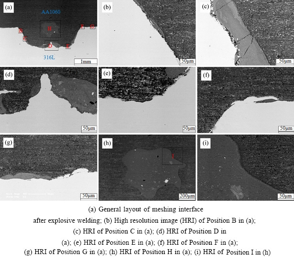
Fig. 8 Morphologies of interface perpendicular to detonation direction obtained by SEM
The morphologies of lower and upper corners of the meshing interface are shown in Fig. 8(e) and Fig. 8(f), respectively. According to Fig. 8(e), the most regions of the interface are bonded in the form of direct bonding, and only a small melting zone is found near the inclined interface. Figure 8(f) shows that there is no melting zone in the upper corner and the interface is connected in the form of direct bonding. As shown in Fig. 8(e) and Fig. 8(f), both the lower and upper corners of the meshing interface are rounded corners, while they were sharp corners before explosive welding, which shows that large plastic deformation of welding materials emerged in the process of bonding interface formation. However, no defect such as cracks and voids was found in the two regions, which showed that excellent bonding was created in the lower and upper corners of the meshing interface.
It can be observed from Fig. 8(g) that melting zone existed in the local region of the upper interface. The thickness of the melting zone is about 20 ��m and there is no defect such as gas porosity and crack, which shows that the upper bonding interface is also excellent. Figure 8(h) shows that a large melting zone is formed at the middle part of the meshing interface, in which some metal particles can be found. A similar phenomenon can be found in previous studies [22]. The formation of the melting zone could be explained by adiabatic heating which resulted in lots of melting zones, and then these melting zones were squeezed inward. Figure 8(i) shows that there is no defect at the interface between the melting zone and aluminum, which indicates that the melting zones do not deteriorate the mechanical properties of bonding interface.
Figures 9 shows the microstructural morphologies of an upper interface parallel to detonation direction. For the Al/Fe bonding interface parallel to detonation direction, both straight [10,14] and wavy [22-24] bonding interfaces have been obtained by researchers. The wavy bonding interface is usually preferred due to the better mechanical properties and more bonding area [25,26]. It was also reported that the bonding interface transformed from straight to wavy interface with increasing the explosive loading [27]. As shown in Fig. 9(a), regular wave interfaces are formed between the aluminum and stainless steel, which shows that the explosive loading is high enough to obtain a wavy interface. From Figs. 9(b) and (c), it can be found that the wavy length and amplitude of the interface are approximately 80 ��m and 20 ��m, respectively. The shape of the waves is asymmetric, which can be attributed to the large difference between density of aluminum and stainless steel, and a similar phenomenon can be found in Ref. [2]. Figures 9(b) and (c) also show that localized melting zones are formed in the wave bonding interface. The formation of the localized melting zones is related to adiabatic heating of trapped jet or adiabatic heating of gases compressed between the two plates [2]. For the Al/Fe bonding interface produced by explosive welding, a hard and brittle intermetallic is often formed in the localized melting zones, which affects the bonding quality and the mechanical properties in a negative manner [10,12,14].
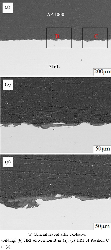
Fig. 9 Morphologies of upper interface parallel to detonation direction obtained by SEM
Figure 10 shows the microstructural morphology of a lower interface parallel to detonation direction. Unlike the upper interface, Fig. 10(a) shows that an irregular wavy interface is formed between the welded materials, and small waves exist in the front or back slope of big waves. The formation of small waves can be attributed to the variations in the velocity distribution at collision point and periodic disturbances of materials [28], which is also the reason of wave formation for explosive welding of two smooth plates. The formation of big wave is related to the fact that the lower bonding interface is inconsistently squeezed along the detonation direction. Figure 10(a) also shows that a large melting zone with some metal particles is formed at the side of the aluminum, which is consistent with the previous discussion. According to Figs. 10(b) and (c), there is no micropores and cracks at the interface, which indicates that the bonding interface is excellent.
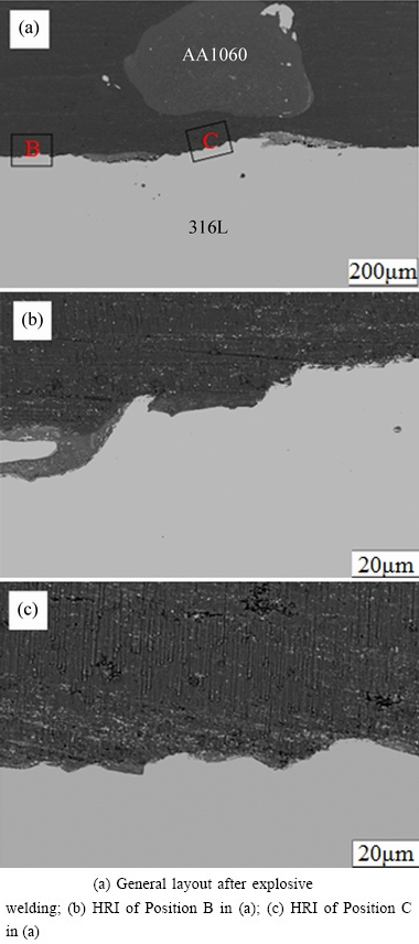
Fig. 10 Morphologies of lower interface parallel to detonation direction obtained by SEM
3.2 Distribution of elements across interface
In order to describe the transition layer between the two welded materials, element line scans were conducted to determine elements distribution across the bonding interface after explosive welding. Figure 11(a) shows element distribution of an upper interface with no melting zone. It can be observed from Fig. 11(a) that the element distribution line is steep, which indicates that the two welded plates are bonded in the form of direct bonding in this region. Figures 11(b), (c) and (d) show element distributions of the upper, inclined and lower interfaces with melting zone, respectively. It can be seen from Figs. 11(b), (c) and (d) that the trends of distribution lines of Fe and Cr are consistent, which is opposite to that of Al. Figures 11(b), (c) and (d) also show a platform at the melting zone of bonding interface, which indicates that the atomic diffusion occurs at the interface, and steady intermetallic compounds may be formed in the melting zones. This result was in agreement with the previous studies [14,29] about element diffusion on the Fe/Al interface after explosive welding. According to Fe-Al phase diagram [30], it is easy to form intermetallic compounds (Al3Fe, AlFe, Fe2Al7, Al5Fe2, FeAl2, etc) at high temperature. During the welding process, the high temperature conditions were met by adiabatic compression at the bonding interface [31], so multiple intermetallic compounds might be formed in the transition zone [10,14,30]. Figure 12 shows the results of element spot scans in the melting zone. According to analysis of the molar fraction ratio of Al to Fe in Fig. 12, it was deduced that the melting zone mainly consisted of the stable phase Al3Fe or Fe2Al5.
3.3 Tensile tests
The average tensile strength and typical stress�C strain curves obtained from tensile tests are shown in Table 5 and Fig. 13, respectively. According to Table 5, the tensile strength of meshing interface 0�� is higher than that of ordinary interface 0��, while the tensile strength of meshing interface 90�� is lower than that of the former two. The former phenomenon may be related to work hardening. Compared to the ordinary interface, the work hardening of the meshing interface was intenser due to the larger bonding area, so a higher tensile strength value was obtained for meshing interface 0��. The latter phenomenon can be attributed to the structure of meshing interface, as shown in Fig. 5. For meshing interface 90��, the tensile strength of the composite depends on the weakest region in which the bonding interface is the lower interface (steel-to-aluminum mass ratio is the minimum). For meshing interface 90�� and ordinary interface 0��, however, the cross-sections are consistent in different regions along the tensile direction, which makes full use of the strength of aluminum and steel. In addition, it is noted that the original tensile strengths of the aluminum and steel are 110 and 620 MPa. Obviously, the tensile strength of the three tests is higher than that of aluminum and lower than that of steel, which is consistent with previous researches [14,32].
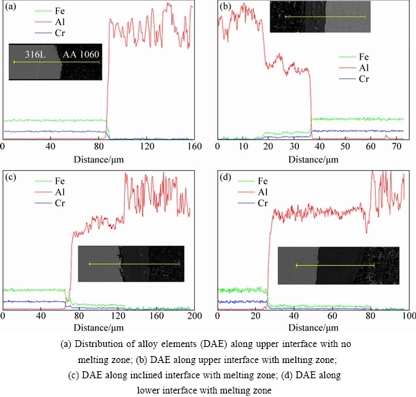
Fig. 11 Distributions of elements across bonding interface
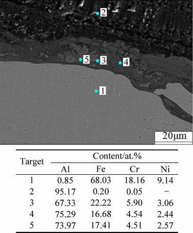
Fig. 12 Element spot scan results of local melted zone
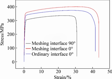
Fig. 13 Typical stress�Cstrain curves obtained by tensile tests
Table 5 Tensile and tensile-shear test results
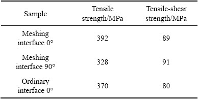
Figure 14 shows the fractographs of the bonding interfaces after tensile tests. It can be observed from Fig. 14(a) that the interfaces are delaminated almost completely, and different regions can be discerned on the fracture surface. Numerous ductile dimples with large size are observed on both the steel side and the Al side away from the interface, as shown in Figs. 14(c) and (e), which show the typical characteristics of ductile fracture. Figure 14(b) shows the unambiguous characteristics of cleavage fracture without any dimple on the steel side near the interfaces, which may be due to the effect of work hardening. In this situation, owing to the low ductility of this region containing some brittle intermetallic phases and severely deformed grains, some cracks were initiated at the interface and propagated along the tensile direction [33]. Figure 14(d) exhibits unambiguous characteristics of ductile fracture with dimples on the Al side near the interfaces. However, the sizes and numbers of the dimples are less than those away from the interface, which indicates that the ductility of Al side at the interface was reduced.
3.4 Tensile shear tests
Shear test is important to assess transition joints and one of the purposes of this study is to improve the shear strength of the bonding interface. Figure 15 shows typical stress�Cdistance curves obtained from the tensile shear tests, and the average tensile shear strength values are listed in Table 5. According to Table 5, the shear strength of ordinary interface 0�� is 80 MPa, which is in agreement with the previous study [32] about shear strength of the Fe/Al interface after explosive welding. The shear strength of meshing interface 0�� is 89 MPa, which is 11% higher than that of ordinary interface 0��. The bonding area of the meshing interface is 25% higher than that of ordinary interface, so higher macroscopic shear strength is obtained. However, the shear strength of the unit bonding area is lower than that of ordinary interface, which can be attributed to the fact that the bonding strength of the inclined interface is lower than that of the upper and lower interfaces. An evidence for this deduction is that defects such as gas porosity, crushed particles and cracks are observed at the inclined interface in Fig. 8(c). The shear strength of 91 MPa is obtained for meshing interface 90��, which is 14% higher than that of ordinary interface. This happened because mechanical locking improves the shear strength, as shown in Fig. 5. Although this method improves the macroscopic mechanical strength of the weld joints, there are also shortcomings such as extra cost for prefabricating grooves in base plate, and more careful design of welding parameters is required due to the complexity of the welding interface. Thus, this method is suitable for manufacturing Al-Fe composite materials with high strength requirement.
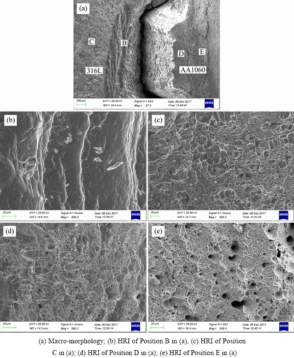
Fig. 14 Fractographs of bonding interface after tensile test
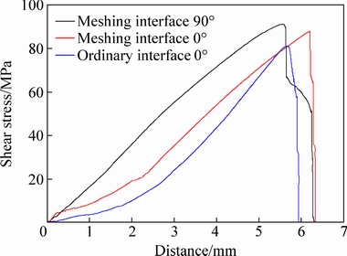
Fig. 15 Typical stress�Cdistance curves obtained by tensile shear tests
3.5 Microhardness tests
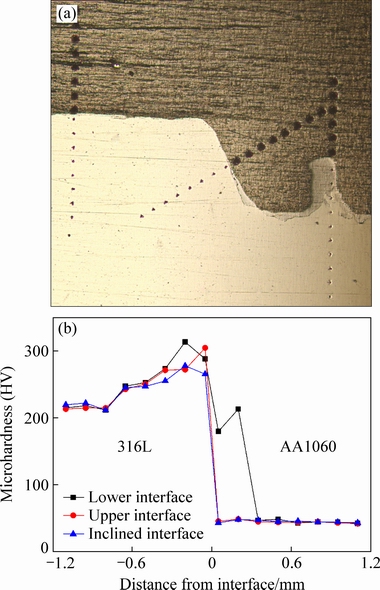
Fig. 16 Microhardness profiles near bonding interfaces
Figures 16(a) and (b) respectively show the test positions and results of the microhardness near the interface. As shown in Fig. 16(b), the microhardness generally decreases with increasing the distance from the welding interface, which can be attributed to work hardening due to the severe plastic deformation in the welding zones. Similar results have been reported by many researchers [4,34]. Figure 16(b) also shows that the microhardness values of steel near the interface are approximately consistent at the upper and lower interface, and they are higher than those at inclined interface. This happened because direct collision between aluminum and steel occurred at the upper and lower interface during explosive welding, while slide occurred between aluminum and steel at the inclined interface. So, the degree of work hardening at the inclined interface was lower than that at upper and lower interface. The maximum microhardness of the steel near the interface was approximately HV 310, which was approximately 44% higher than HV 215 of the steel far away from the interfacial region. The maximum microhardness of the aluminum near the interface was approximately HV 48, which was approximately 12% higher than the hardness (HV 43) of the aluminum far away from the interfacial region. The average microhardness of the solid solution at the bonding interface was HV 190, which was slightly higher than the average hardness of the aluminum and steel of HV 179 near the solid solution.
3.6 Bending test
Meshing interfaces 0�� and 90�� were both prepared for bending tests, and all specimens were bent to 180��. Figure 17 shows the specimens after bending tests. As shown in Fig. 17(a), macro cracks are observed at the bonding interface for specimen A, and Figs. 17(c) and (d) show the micro cracks of specimens C and D, which are consistent with the results of previous researches [22]. Due to the fact that the brittle Fe-Al compounds existed at the bonding interface, it is easy to result in uncoordinated deformation and accelerate the fracture process of the bonding interface under the effect of an external force [6]. However, no separation or fracture has been noticed for Specimen B (inner bending for meshing interface 90��), which could be attributed to the meshing interface preventing the initiation of crack under this external force.
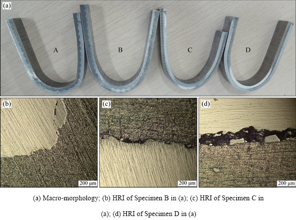
Fig. 17 Specimen morphologies after bending tests
4 Conclusions
(1) Metallurgical bonding without any pores has been achieved for meshing interface of aluminum to stainless steel. Two types of bond were observed at the bonding interface, namely direct bonding and melting zone bonding, and the EDS analysis indicated that the melting zone mainly consisted of the stable phase Al3Fe or Fe2Al5.
(2) Regular wavy interfaces were observed at the upper interface parallel to detonation direction, while irregular wavy interfaces were formed at the lower interface parallel to detonation direction.
(3) Tensile strength of meshing interface 0�� was higher than that of ordinary interface 0��, while the tensile strength of meshing interface 90�� was lower than that of the ordinary interface 0��. Fractography studies on tensile specimens showed cleavage fracture on the steel side and ductile fracture on the aluminum side near the interfaces.
(4) The tensile shear test results showed that the shear strength of the meshing interface 0�� and 90�� was increased by 11% and 14%, respectively, compared to that of the ordinary Al-Fe transition joints.
(5) The values of microhardness decreased as the distance from the interface increased. The average microhardness of the solid solution at the bonding interface was slightly higher than the average hardness of the aluminum and steel near the solid solution.
(6) No separation or fracture has been noticed for meshing interface 90�� after inner bending. However, cracks were observed at the bonding interface under other bending condition due to the existence of brittle Fe-Al compounds.
References
[1] SHIRAN M K G, KHALAJ G, POURALIAKBAR H, JANDAGHIC M R, DEHNAVIA A S, BAKHTIARIDET H. Multilayer Cu/Al/Cu explosive welded joints: Characterizing heat treatment effect on the interface microstructure and mechanical properties [J]. Journal of Manufacturing Processes, 2018, 35: 657-663.
[2] MOUSAVI S A A A, SARTANGI P F. Experimental investigation of explosive welding of cp-titanium/AISI 304 stainless steel [J]. Materials and Design, 2009, 30: 459-468.
[3] BORCHERS C, LENZ M, DEUTGES M, KLEIN H, GARTNER F, HAMMERSHMIDT M, KREYEC H. Microstructure and mechanical properties of medium-carbon steel bonded on low-carbon steel by explosive welding [J]. Materials and Design, 2016, 89: 369-376.
[4] FINDIK F. Recent developments in explosive welding [J]. Materials and Design, 2011, 32: 1081-1093.
[5] BAZARNIK P, ADAMCZYK-CIESLAK B, GALKA A, PLONKA B, SNIEZEK L, CANTONI M, LEWANDOWSKA M. Mechanical and microstructural characteristics of Ti6Al4V/AA2519 and Ti6Al4V/ AA1050/AA2519 laminates manufactured by explosive welding [J]. Materials and Design, 2016, 111: 146-157.
[6] NING Jie, ZHANG Lin-jie, XIE Miao-xia, YANG Han-Xin, YIN Xian-qing, ZHANG Jian-xun. Microstructure and property inhomogeneity investigations of bonded Zr/Ti/steel trimetallic sheet fabricated by explosive welding [J]. Journal of Alloys and Compounds, 2017, 698: 835-851.
[7] APRAMANIK. Effects of reinforcement on wear resistance of aluminum matrix composites [J]. Transactions of Nonferrous Metals Society of China, 2016, 26: 348-358.
[8] WANG Chun-yang, JIANG Yan-bin, XIE Jian-xin, XU Sheng, ZHOU De-jing, ZHANG Xiao-jun. Formation mechanism and control of aluminum layer thickness fluctuation in embedded aluminum�Csteel composite sheet produced by cold roll bonding process [J]. Transactions of Nonferrous Metals Society of China, 2017, 27: 1011-1018.
[9] SHIRAN M K G, KHALAJ G, POURALIAKBAR H, JANDAGHI M, BAKHTIARI H, SHIRAZI M. Effects of heat treatment on the intermetallic compounds and mechanical properties of the stainless steel 321�Caluminum 1230 explosive-welding interface [J]. International Journal of Minerals, Metallurgy, and Materials, 2017, 24: 1267-1277.
[10] HAN J H, AHN J P, SHIN M C. Effect of interlayer thickness on shear deformation behavior of AA5083 aluminum alloy/SS41 steel plates manufactured by explosive welding [J]. Journal of Materials Science, 2003, 38: 13-18.
[11] YIN Fu-cheng, HU Jing-xian, CHENG Zhi, LI Si-han. Phase equilibria of Al-Fe-Sn ternary system [J]. Transactions of Nonferrous Metals Society of China, 2018, 28: 282-289.
[12] HOKAMOTO K, IZUMA T, FUJITA M. New explosive welding technique to weld [J]. Metallurgical Transactions A, 1993, 24: 2289-2297.
[13] ACEVES S M, ESPINOSA-LOZA F, ELMER J W, HUBER R. Comparison of Cu, Ti and Ta interlayer explosively fabricated aluminum to stainless steel transition joints for cryogenic pressurized hydrogen storage [J]. International Journal of Hydrogen Energy, 2015, 40: 1490-1503.
[14] LI Xue-jiao, MA Hong-hao, SHEN Zhao-wu. Research on explosive welding of aluminum alloy to steel with dovetail grooves [J]. Materials and Design, 2015, 87: 815-824.
[15] GULENC B, KAYA Y, DURGUTLU A, GULENC I T, YILDIRIM M S. Production of wire reinforced composite materials through explosive welding [J]. Archives of Civil and Mechanical Engineering, 2016, 16: 1-8.
[16] MA Rui, WANG Yao-hua, WU Ji-hong DUAN Mian-jun. Explosive welding method for manufacturing ITER-grade 316L(N)/CuCrZr hollow structural member [J]. Fusion Engineering and Design, 2014, 89: 3117-3124.
[17] ATHAR M M H, TOLAMINEJAD B. Weldability window and the effect of interface morphology on the properties of Al/Cu/Al laminated composites fabricated by explosive welding [J]. Materials and Design, 2015, 86: 516-525.
[18] GB/T 6396-2008. Clad steel plates-mechanical and technological test [S]. China National Standardization Management Committee, 2008-05-13.
[19] MANIKANDAN P, HOKAMOTO K, FUJITA M, RAGHUKANDAN K, TOMOSHIGE R. Control of energetic conditions by employing interlayer of different thickness for explosive welding of titanium/304 stainless steel [J]. Journal of Materials Processing Tech, 2008, 195: 232-240.
[20] PAUL H, LITYNSKADOBRZYNSKA L, PRAZMOWSKI M. Microstructure and phase constitution near the interface of explosively welded aluminum/copper plates [J]. Metallurgical and Materials Transactions A, 2013, 44: 3836-3851.
[21] LEE W B, BANG K S, JUNG S B. Effects of intermetallic compound on the electrical and mechanical properties of friction welded Cu/Al bimetallic joints during annealing [J]. Journal of Alloys and Compounds, 2005, 390: 212-219.
[22] GUO Xun-zhong, FAN Min-yu, WANG Liu-an, MA Fu-ye. Bonding interface and bending deformation of Al/316LSS clad metal prepared by explosive welding [J]. Journal of Materials Engineering and Performance, 2016, 25: 1-7.
[23] GUO Xun-zhong, WANG Hui, LIU Zhong-li, WANG Liu-an, MA Fu-ye, TAO Jie. Interface and performance of CLAM steel/aluminum clad tube prepared by explosive bonding method [J]. International Journal of Advanced Manufacturing Technology, 2016, 82: 1-6.
[24] SUN Xian-jun, TAO Jie, GUO Xun-zhong. Bonding properties of interface in Fe/Al clad tube prepared by explosive welding [J]. Transactions of Nonferrous Metals Society of China, 2011, 21: 2175-2180.
[25] XIAO Hong-bo, WANG Shao-gang, BEN Hai-feng. Microstructure and mechanical properties of Ti/Al explosive cladding [J]. Materials and Design, 2014, 56: 1014-1019.
[26] BINA M H, DEHGHANI F, SALIMI M. Effect of heat treatment on bonding interface in explosive welded copper/stainless steel [J]. Materials and Design, 2013, 45: 504-509.
[27] ACARER M, GULENC B, FINDIK F. Investigation of explosive welding parameters and their effects on microhardness and shear strength [J]. Materials and Design, 2003, 24: 659-664.
[28] MOUSAVI S A A A, AL-HASSANI S T S. Finite element simulation of explosively-driven plate impact with application to explosive welding [J]. Materials and Design, 2008, 29: 1-19.
[29] GUO Xun-zhong, TAO Jie, WANG Wen-tao, LI Hua-guan, WANG Chen. Effects of the inner mould material on the aluminium�C316L stainless steel explosive clad pipe [J]. Materials and Design, 2013, 49: 116-122.
[30] TRICARICO L, SPINA R, SORGENTE D, BRANDIZZI M. Effects of heat treatments on mechanical properties of Fe/Al explosion-welded structural transition joints [J]. Materials and Design, 2009, 30: 2693-2700.
[31] AKBARI-MOUSAVI S A A, BARRETT L M, AL-HASSANI S T S. Explosive welding of metal plates [J]. Journal of Materials Processing Tech, 2008, 202: 224-239.
[32] JIN J Y, HONG S I. Effect of heat treatment on tensile deformation characteristics and properties of Al3003/STS439 clad composite [J]. Materials Science and Engineering A, 2014, 596: 1-8.
[33] HOSEINI-ATHAR M M, TOLAMINEJAD B. Interface morphology and mechanical properties of Al-Cu-Al laminated composites fabricated by explosive welding and subsequent rolling process [J]. Metals and Materials International, 2016, 22: 670-680.
[34] CARVALHO G, GALVAO I, MENDES R, LEAL R M, LOUREIRO A. Explosive welding of aluminium to stainless steel [J]. Journal of Materials Processing Technology, 2018, 262: 340-349.
��ը����Al-Fe���Ͻ�����۽ṹ����ѧ����
�� ��1�������1,2��������1���´���1��������1
1. �й���ѧ������ѧ �й���ѧԺ������ѧ��Ϊ������ص�ʵ���ң��Ϸ� 230026��
2. �й���ѧ������ѧ ���ֿ�ѧ�����ص�ʵ���ң��Ϸ� 230026
ժ Ҫ��Ϊ�����Al-Fe��ը���ӽ������ѧ���ܣ�ͨ���ڻ�����Ԥ����β�۵ķ�����������ͽ�Ͻ��棬��ϵͳ�о����Ͻ�����۽ṹ����ѧ���ܡ��۽ṹ�۲���������Ͻ���ʵ����û�п���ұ����, ��Ϸ�ʽΪֱ�ӽ�Ϻ��ۻ�����ϡ�������Ʒ����������ڽ��渽���ֲ�Ϊ�������Ѷ�����Ϊ���Զ��ѡ��������Խ���������������ͨ�����ֱ�ը���ӽ��棬0���90�� ���Ͻ���ļ���ǿ�ȷֱ����11%��14%������������������ӣ��������������Ӳ��ֵ���½������ڴ��ڴ���Fe-Al��������������������н�������ѷ졣
�ؼ��ʣ���ը���ӣ����Ͻ��棻���������
(Edited by Bing YANG)
Foundation item: Projects (51674229, 51374189) supported by the National Natural Science Foundation of China; Project (WK2480000002) supported by Fundamental Research Funds for Central Universities, China
Corresponding author: Hong-hao MA; Tel: +86-17755131576; E-mail: hhma@ustc.edu.cn
DOI: 10.1016/S1003-6326(19)64978-2
Abstract: In order to improve the mechanical properties of Al-Fe transition joints manufactured by explosive welding, meshing bonding interfaces were obtained by prefabricating dovetail grooves in base plates. The microstructure and mechanical properties of the meshing interfaces were systematically investigated. The microstructure observation showed that metallurgical bonding without pores was created in the form of direct bonding and melting zone bonding at the interface. Fractography on tensile specimens showed cleavage fracture on the steel side and ductile fracture on the aluminum side near the interfaces. The tensile shear test results indicated that the shear strength of the meshing interface 0�� and 90�� was increased by 11% and 14%, respectively, when being compared to that of the ordinary Al-Fe transition joints. The values of microhardness decreased as the distance from the interface increased. After three-point bending, cracks were observed at the bonding interface for some specimens due to the existence of brittle Fe-Al compounds.
