
Trans. Nonferrous Met. Soc. China 24(2014) 477-483
Three-dimensional modeling of effect of surface intermetallic phase on surface defects of Al-Fe-Si aluminum foils during twin-roll casting
Yuan-zhi ZHU1,3, Qiang WAN2, Bing-liang LI3, Feng ZHOU3, Ya-feng ZHANG1
1. College of Mechanical Electronical and Engineering, North China University of Technology, Beijing 100144, China;
2. China Academy of Engineering Physics, Mianyang 621900, China;
3. School of Materials and Metallurgy, Wuhan University of Science and Technology, Wuhan 430081, China
Received 2 February 2013; accepted 10 December 2013
Abstract:
Scanning electron microscopy and X-ray energy dispersive spectrum analysis show that the clusters of intermetallic AlFeSi particle are distributed on or near the aluminum foil stock surfaces heterogeneously. 3D finite element modeling shows that these clusters of hard particles induce the fracture of the nano-scale lubricant oil film at first and further lead to severe deformation in the nearby aluminum foil substrate along the rolling direction. Consequently, the optical property in this region differs from that in the surroundings, resulting in surface defects.
Key words:
Al-Fe-Si alloy; precipitated phase; aluminum foils; lubricant oil film; twin-roll cast; 3D modeling;
1 Introduction
Aluminum foils are widely used in the food, medical, and electronics industries. These foils are usually thinner than 100 ��m, and some are even as thin as several microns. Minor defects such as pores, secondary precipitates, and inclusions will lead to the deterioration of the surface quality and mechanical property of foil products. Thus, the microstructure of the alloy used for foils should be strictly controlled. The effects of multiple factors on aluminum foil surface defects have been investigated [1,2]. KELES and DUNDAR [3] studied the influence of inclusions on aluminum foil surface defects during the foil rolling process. ZHU et al [4] related these surface defects with secondary precipitates in the alloy.
The morphology, size, and distribution of hard secondary precipitates in aluminum foils largely depend on the microstructure of aluminum foil stock before foil rolling. In turn, this microstructure is strongly affected by the fabrication process. There are two commonly used methods for producing aluminum foil stock, namely, hot rolling (HR) and twin-roll casting (TRC). HR is a traditional method of aluminum foil stock production. In this method, billets with thicknesses of 50-150 mm are first obtained by casting, and then they are hot- or cold-rolled into 0.3-0.5 mm thick aluminum foil stock. The HR technology for aluminum foil production is well established. On the other hand, twin-roll casting is a novel method in which billets with thicknesses of less than 10 mm are produced. This method is simpler, more energy efficient, and more economical than the traditional HR process. The production of aluminum foil stock using TRC sheets is very interesting. However, the initial thicknesses of TRC sheets are usually much lower than those of as-cast billets using the traditional HR method, although subsequent hot- and cold-rolling processes are also required to produce aluminum foils via the twin-roll casting method. Sheets for foils produced by twin-roll casting have different microstructural characteristics from those produced by HR. In twin-roll casting, liquid aluminum is cooled by two rotating rollers with circulating cooling water. The grain size of the billet is much smaller than that of the traditional as-cast billet prepared using HR. The distribution of particles, solute atoms, and eutectic phases in the TRC billet along the thickness direction is much more heterogeneous than that in HR billets [5-7]. A much lower reduction rate may also occur in the production of aluminum sheets by twin-roll casting. Therefore, there are some difficulties in the fabrication of aluminum foils with TRC sheets. For instance, the 1xxx and 8xxx series of aluminum are typical alloys for aluminum foil production. Aluminum foils with stable and high surface quality can be obtained when the aluminum foil stock is produced by the HR method using these alloys [8,9]. However, matte defects often occur on the surface of aluminum foils fabricated from TRC aluminum stocks [10,11]. The intermetallic phase of Fe in the alloy has been reported to result in surface matte defects because of the interaction of these intermetallic phase particles with the lubricants in the foil rolling process [12-14]. The interaction of intermetallic phases in very thin foils with thickness of several nanometers is not clear.
In this work, the interaction between the secondary hard phase and ultra-thin lubricant oil in foil rolling was investigated to gain a deep insight into the connections between the secondary hard phases and matte defects on the surfaces of foils produced by twin-roll casting. The expected results may be helpful to control secondary hard particles in TRC foil stocks during their fabrication process.
2 Experimental
Billets of AA1235 alloy with 7 mm thickness were produced by the twin-roll casting technique and hot rolled into sheets with 4 mm thickness at 580 ��C. The sheets were tempered for 2 h at 480 ��C and further cold-rolled into sheets with 0.35 mm thickness, hereafter denoted as TRC foil stocks. Typical AA1235 aluminum foil stocks with 0.35 mm thickness were also prepared by the traditional HR process for comparison. The HR AA1235 aluminum foil stocks were produced under the same heat treatment process as the TRC foil stocks. Both TRC and HR stocks with 0.35 mm thickness were subsequently rolled into foils with 0.01 mm thickness on the same foil rolling mill. Matte defects on the surfaces of both types of foils were carefully checked.
A field emission scanning electron microscope (FESEM, FEI Sirion 200) attached with an energy dispersive spectroscope (EDS) analyzer and a transmission electron microscope (TEM, Hitachi H-800) were used to study the effect of intermetallic particles on the surface quality of the aluminum foils.
The effects of hard intermetallic phases on the surface quality, such as matte defects, were investigated by both experiment and finite element modeling (FEM), for which Abaqus 6.8 was used.
3 Results
Both TRC and HR foil stocks were rolled into foils with 0.01 mm thickness in a foil rolling mill. The surface qualities of the foils were checked carefully. Matte defects are found on the surface of TRC foils but not on that of HR foils (Fig. 1(a)). The defects are almost linearly arranged in a zone with tens of microns width along the rolling direction (Fig. 1(b)). Traces of shearing are visible along the matte defect zone, and the zone boundaries vertical to the rolling direction are irregular (Fig. 1(a)). A high-magnification image of the TRC foil surface microstructure reveals a cluster of secondary precipitates within the matte defect zone (Fig. 1(c)). These hard intermetallic particles have been considered as the main reason for the matte defects of TRC foils [4].
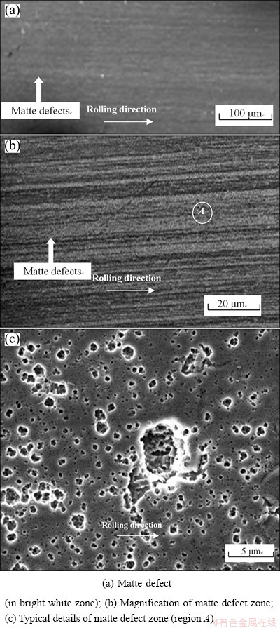
Fig. 1 Micrographs of a typical matte defect
The microstructures of the transverse section near the surface of the TRC and HR sheets are compared in Fig. 2. It shows a wavy boundary and obvious defects near the TRC sheet surface, with clusters of precipitates forming within or around the defects (pores, inclusions, or coarse precipitates). These clusters of precipitates may originate from the surface segregation occurring on the original twin roll cast billet, which is crushed into the foil surface [15]. The surface of the HR sheet is flat and has a more uniform microstructure than that of the TRC sheet. The sizes of clusters are 20-50 ��m.
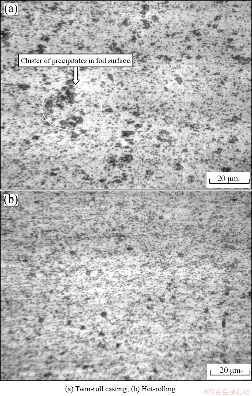
Fig. 2 Microstructures of transverse section near foil stock surface
The TEM images of the hard particles found on the TRC sheet with 0.35 mm thickness are shown in Fig. 3. A large number of spherical particles can be observed in the microstructure of the TRC sheet. The chemical compositions of the particles were obtained using EDS. The results show that the spherical or irregular particles in the TRC sheet are AlFeSi, which may segregate in clusters near the surface of aluminum foil stock. The hardness of AlFeSi is about 15 GPa [16].
4 Discussion
4.1 Analysis of experimental results
The clusters of intermetallic particles on or near the TRC strip surface (Fig. 3) are composed of Fe-enriched phases, which are much harder than the aluminum matrix. The sizes of clusters are several microns, which are much bigger than the thickness of the lubricant oil film. If the clusters project on the strip surface and make contact with the lubricant oil film, they are going to interact. This kind of interaction can be investigated by FEM simulation as follows.
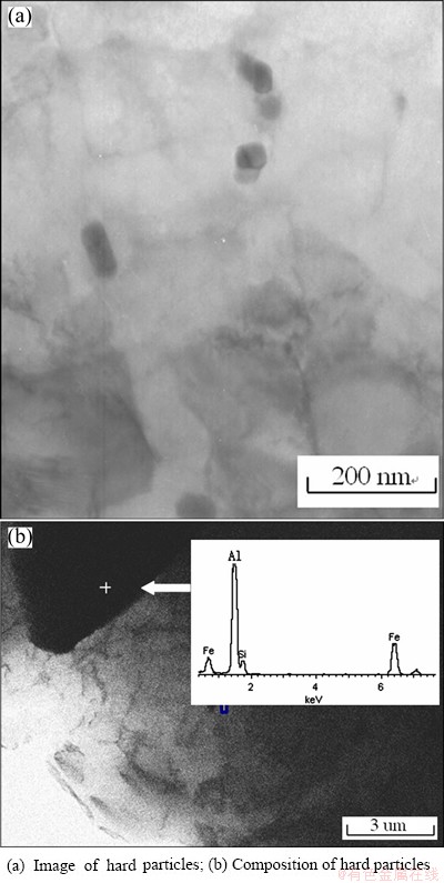
Fig. 3 TEM images of TRC stock foil
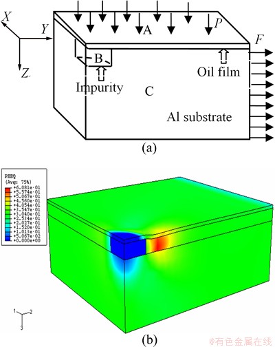
Fig. 4 Sketch (a) and plastic strain distribution (b) of model
4.2 Numerical study of interaction between hard particles and oil film
To investigate the mechanism of a destructive band, the strain and stress of the thin film are analyzed by FEM using an Abaqus code during the rolling process. Figure 4 shows the symmetric model of the film and simulated results. In Fig. 4, A is the oil film, B is the intermetallic phase cluster in the aluminum film, and C is the aluminum film. Generally, the hardness of intermetallic particles is twice than that of the aluminum film. The oil film has dimensions of 35 ��m��35 ��m��100 nm, elastic modulus of 20 kPa, and yield stress of 39 kPa according to the experiment of the reported procedure [17]. The intermetallic phase cluster is modeled as a column with 4 ��m diameter and 2 ��m thickness. Given that the hardness of the intermetallic phase cluster is twice that of the aluminum film, the intermetallic phase cluster can be considered elastic during the simulation, and the elastic modulus is 60 GPa according to Ref. [18]. The aluminum film has dimensions of 35 ��m��35 ��m��12 ��m, elastic modulus of 69 GPa [19], and plastic strain of 0.32. The rolling loading is modeled as homogenous tensile loading along the Y direction and pressure along the Z direction. In cases where the model has axial symmetry, the eighth model is analyzed by Abaqus (Fig. 4(a)). The C3D81 incompatible mode element is used in the analysis. C3D81 is a kind of Abaqus solid element with eight nodes for FEM calculation. In the FEM mode, the assigned numbers of elements for aluminum substrate, oil film, and impurity are 20000, 10000 and 2000, respectively. For the convenience of defining the geometry of the impurity and aluminum foil, the aluminum foil is divided into two parts. One part has the same thickness as the impurity, and the other only contacts with the former aluminum part and impurity. These two aluminum parts are assigned the same material property and merged before the simulation. Thus, the division of the aluminum foil in the construction of a geometric model does not affect the accuracy of the simulation results. The modeling results, i.e., the plastic strain distribution under a tension stress of 300 MPa and a pressure of 100 kPa, are shown in Fig. 4(b). The maximal plastic strain occurs near the intermetallic phase cluster along the Y-axis. The coordinate system of X, Y, and Z in Fig. 4(a) corresponds to the coordinate system 1, 2 and 3, respectively, in Figs. 4(b), and Figs. 5-9. The maximal plastic strain and von Mises stress of the oil film are found at the same location. Figures 5-7 show the plastic strain and von Mises stress evolution during the loading process. Figures 7(a) and (b) show the plastic strain and von Mises stress values along the Y-axis in the oil film at the last loading step. The maximal plastic strain of 0.48 and maximal von Mises stress of 38 kPa appear at about 8 ��m from the center along the Y-axis. The maximal plastic strain and von Mises stress near the intermetallic phase cluster in the oil film may destroy the integrity of the oil film during the rolling process, which induces immediate contact between the aluminum film and roller. The ultimate result is the destructive band behind the impurity in the aluminum film.
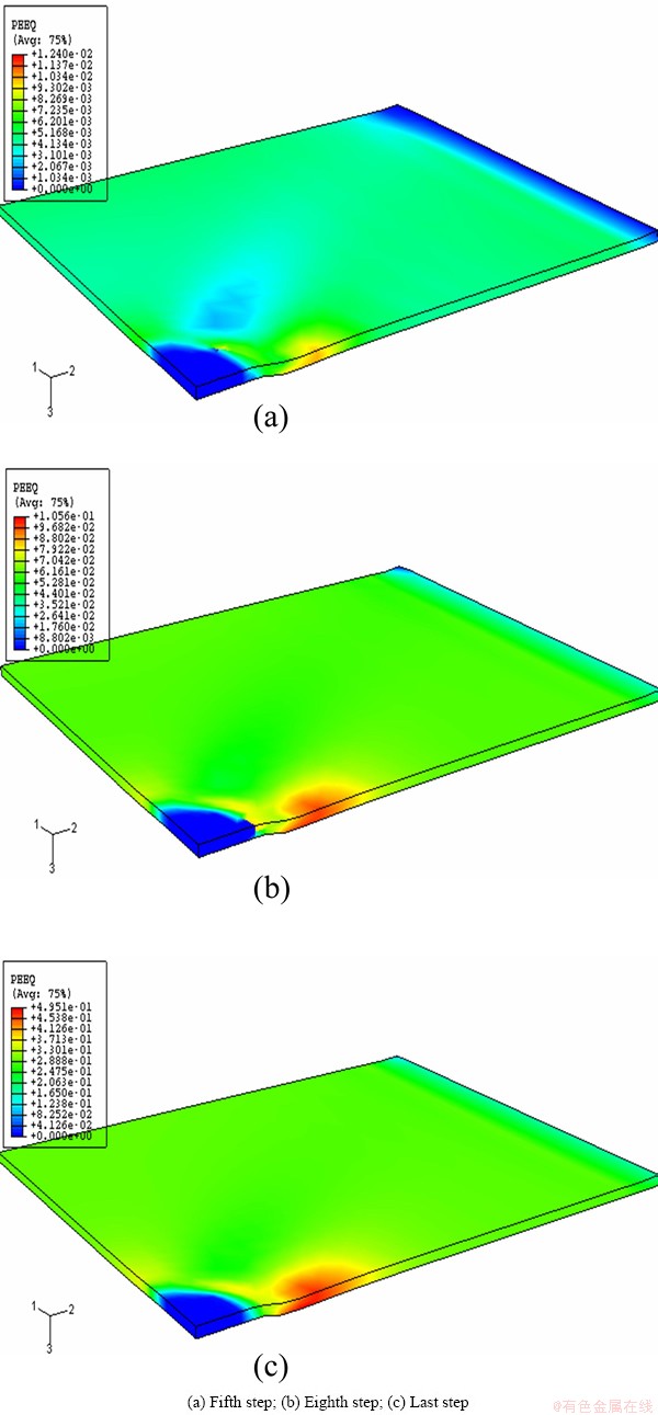
Fig. 5 Plastic strain distribution of oil film during loading process
The maximum principal stress reaches 1686 MPa (Fig. 8). There is a sharp change in the stress in the bottom right of the inclusion, which may result from the shear torque caused by the friction from the oil film and constraint from the aluminum foil at the bottom. The inclusions may have been broken at such a high stress. These results coincide with the SEM observations. The cluster of secondary particles may result from the fractured coarse particles. However, these kinds of regions still have higher strength and hardness values than the others, leading to stress concentration in the contacted oil foil.
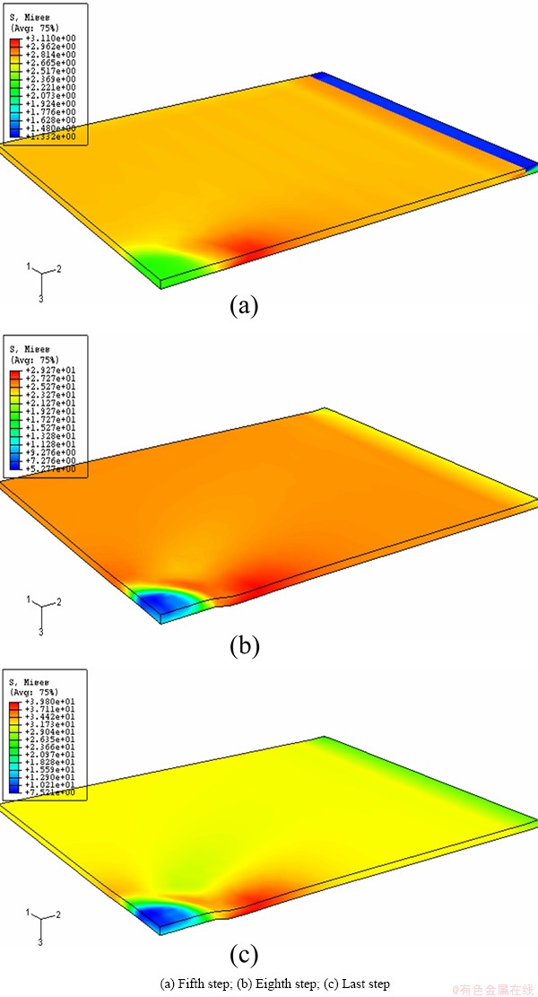
Fig. 6 Von Mises stress distribution of oil film during loading process
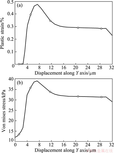
Fig. 7 Von Mises stress (a) and plastic strain (b) of oil film along Y-axis at the last step
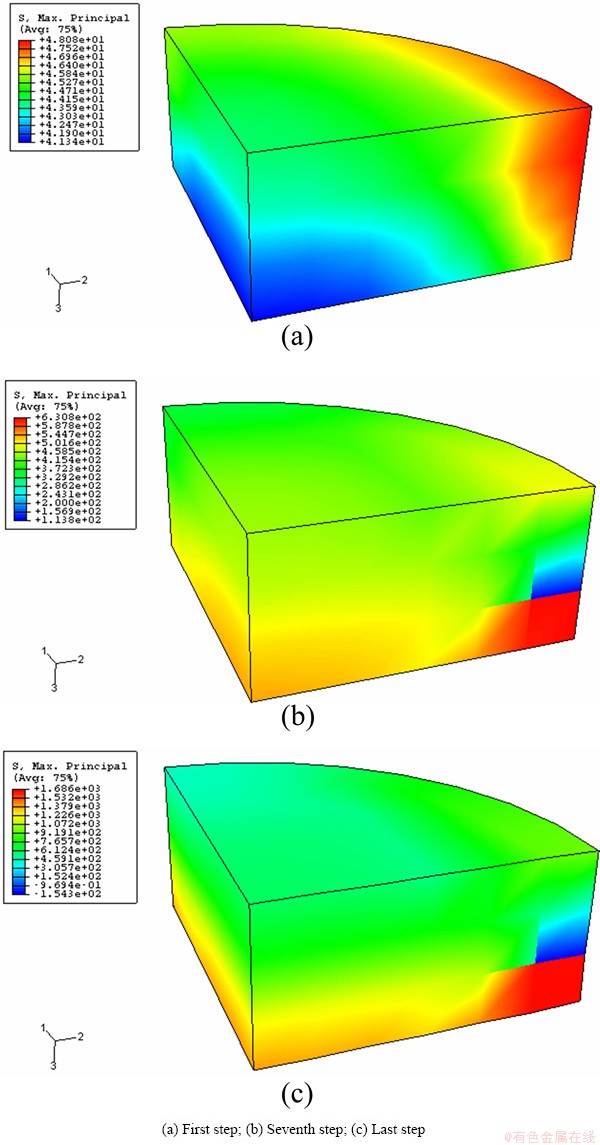
Fig. 8 Maximum principal stress distribution of impurity
The maximum von Mises stress in the aluminum foil substrate reaches 400 MPa (Fig. 9), which is much greater than the yield stress of this aluminum alloy. The high concentration of stress in the regions before the hard particles may cause severe heterogeneous deformation, resulting in a different color in this region from that in others.
The strain concentration in the substrate changes with the rolling time (Fig. 9). There is a region of high strain concentration near the hard particles. The area with a high strain concentration becomes longer as the rolling proceeds.
5 Conclusions
1) Clusters of hard AlFeSi particles are observed along matte defects on the surface of TRC aluminum foils. The cluster of secondary particles may result from the fractured coarse particles, which leads to the fracture of the contacted oil foil.
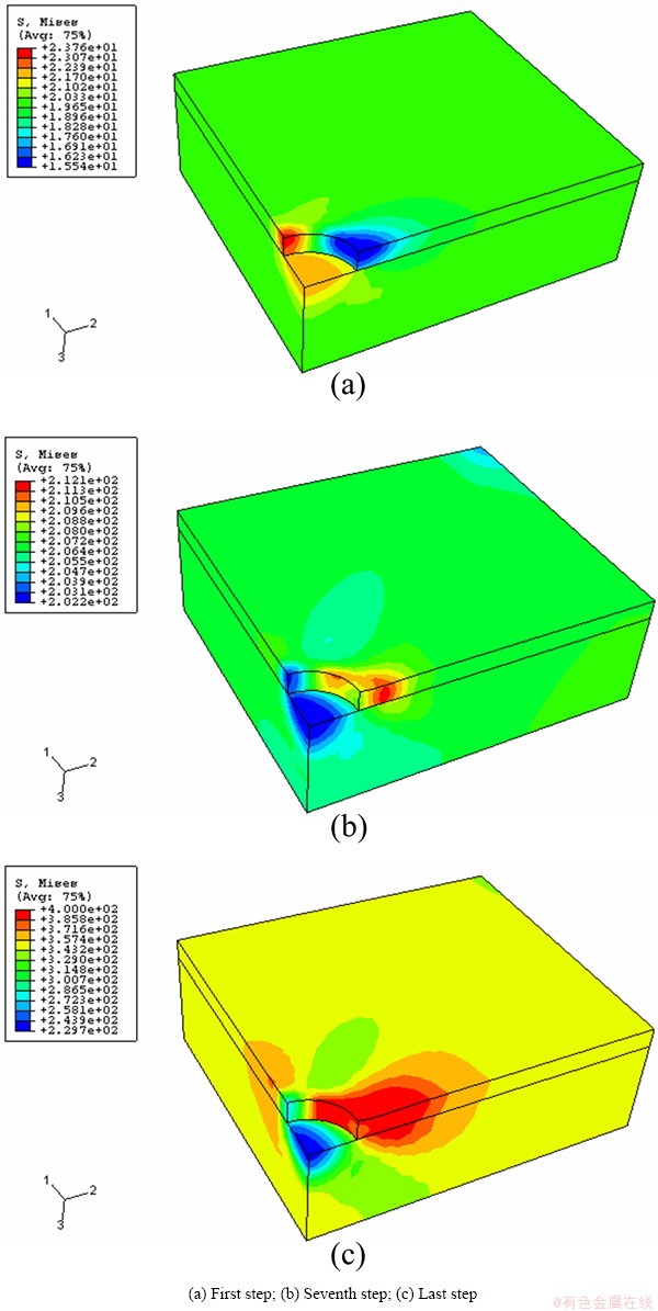
Fig. 9 Von Mises stress distribution of substrate
2) Hard particles cause severe heterogeneous deformation in the nearby aluminum foil substrate, which results in a different color in this region from that of others.
References
[1] EIZADJOU M, DANESH MANESH H, JANGHORBAN K. Investigation of roll bonding between aluminum alloy strips [J]. Materials & Design, 2008, 29(4): 909-913.
[2] TILLOUS K, TOLL-DUCHANOY T, BAUER-GROSSE E, HERICHER L, GEANDIER G. Microstructure and phase composition of microarc oxidation surface layers formed on aluminium and its alloys 2214-T6 and 7050-T74 [J]. Surface & Coatings Technology, 2009, 203(19): 2969-2973.
[3] KELES O, DUNDAR M. Aluminum foil: Its typical quality problems and their causes [J]. Journal of Materials Processing Technology, 2007, 186(1-3): 125-137.
[4] ZHU Y Z, HUANG R Y, ZHU Z, XIANG Z D. Comparative study on effects of microstructures of hot rolled and twin roll casting 1235 aluminium alloy on surface quality of aluminium foils produced [J]. Materials Science and Technology, 2011, 27(4): 761-766.
[5] DAS S, LIM N S, KIM H W, PARK C G. Effect of rolling speed on microstructure and age-hardening behaviour of Al-Mg-Si alloy produced by twin roll casting process [J]. Materials & Design, 2011, 32(8-9): 4603-4607.
[6] LIU Xiao-bo, XU Qing-yan, JING Tao, LIU Bai-cheng. Microstructure of aluminum twin-roll casting based on Cellular Automation [J]. Transactions of Nonferrous Metals Society of China, 2008, 18(4): 944-948.
[7] DAS S, LIM N S, SEOL J B, KIM H W, PARK C G. Effect of the rolling speed on microstructural and mechanical properties of aluminum-magnesium alloys prepared by twin roll casting [J]. Materials & Design, 2010, 31(3): 1633-1638.
[8] SANDERS R E. Technology innovation in aluminum products [J]. JOM, 2001, 53(2): 21-25.
[9] SHABEL B S, BAUMANN S F, SANDERS R E. Method of making aluminum foil or fin shock alloy product: US, 4737198 [P]. 1988-04-12.
[10] CHEN Shou-dong, CHEN Jing-chao. Simulation of microstructures in solidification of aluminum twin-roll casting [J]. Transactions of Nonferrous Metals Society of China, 2012, 22(6): 1452-1456.
[11] BIROL Y. The performance of Al-Ti-C grain refiners in twin-roll casting of aluminium foilstock [J]. Journal of Alloys and Compounds, 2007, 430(1-2): 179-187.
[12] QIN Y X, SHEN L, HAN M H. The cause and preventable measurement of sparkling spot on aluminium decorative laminate [J]. Light Alloy Fabrication Technology, 2003, 31(6): 21-23.
[13] LIU J, XU C L, SHI Y S. Effect of chemical component and fabrication process on properties of aluminum alloy sheet uesd for bottle lid [J]. Light Alloy Fabrication Technology, 2003, 31(6): 27-28.
[14] SHAN De-bin, ZHANG Yan-qiu, WANG Yong, XU Wen-chen. Defect analysis of complex-shape aluminum alloy forging [J]. Transactions of Nonferrous Metals Society of China, 2006, 16(S3): s1574-s1579.
[15] FORBORD B, ANDERSSON B, INGVALDSEN F, AUSTEVIK O, HORST J A, SKAUVIK I. The formation of surface segregates during twin roll casting of aluminium alloys [J]. Materials Science and Engineering A, 2006, 415(1-2): 12-20.
[16] MURALI S, SRITHARAN T, HING P. Self-propagating high temperature synthesis of AlFeSi intermetallic compound [J]. Intermetallics, 2003, 11(3): 279-281.
[17] JOHNSON K L, TEVAARWERK J L. Shear behaviour of elastohydrodynamic oil films [J]. 1977, 356(1685): 215-236.
[18] CESCHINI L, BOROMEI L, MORRI A, SEIFEDDINE S, SVENSSON I L. Effect of Fe content and microstructural features on the tensile and fatigue properties of the Al-Si10-Cu2 alloy [J]. Materials & Design, 2012, 36: 522-528.
[19] LIAO Y, WELLS V. Estimation of complex modulus using wave coefficients [J]. Journal of Sound and Vibration, 2006, 295(1-2): 165-193.
˫���������Ʊ�Al-Fe-Si�Ͻ����������еڶ���Ա�������Ӱ���3Dģ��
��Զ־1,3���� ǿ2�������3���� ��3�����ŷ�1
1. ������ҵ��ѧ ����ѧԺ������ 100144��
2. �й����������о�Ժ������ 621900��
3. �人�Ƽ���ѧ ������ұ��ѧԺ���人 430081
ժ Ҫ������ɨ������������������Լ�3D����Ԫģ����ֶ��о���۵ڶ�������������γ�֮��Ĺ�ϵ�� �о���������������ë���е�AlFeSi���ӳ���״�ֲ���ë�ϱ��������档Ӳ����������������ʱ��������Ĥ����ã���ʹ���Ӹ���������Ĥ���ѣ����������������������Ĥ���巢�����ر��Σ����ܱ߲���ɫ��γɱ���������
�ؼ��ʣ�Al-Fe-Si�Ͻ������ࣻ����������Ĥ��˫��������3Dģ��
(Edited by Chao WANG)
Foundation item: Project (51074117) supported by the National Natural Science Foundation of China; Project (2009CDA044) supported by the Foundation for Distinguished Young Scientists of Hubei Province, China; Projects (201104493, 20100471161) supported by the China Postdoctoral Science Foundation
Corresponding author: Yuan-zhi ZHU; Tel: +86-10-88802301; E-mail: tozyz@16.3com
DOI:v 10.1016/S1003-6326(14)63085-5
Abstract: Scanning electron microscopy and X-ray energy dispersive spectrum analysis show that the clusters of intermetallic AlFeSi particle are distributed on or near the aluminum foil stock surfaces heterogeneously. 3D finite element modeling shows that these clusters of hard particles induce the fracture of the nano-scale lubricant oil film at first and further lead to severe deformation in the nearby aluminum foil substrate along the rolling direction. Consequently, the optical property in this region differs from that in the surroundings, resulting in surface defects.
