
J. Cent. South Univ. Technol. (2011) 18: 2021-2030
DOI: 10.1007/s11771-011-0937-6![]()
A novel digital control strategy of three-phase shunt active power filter under non-ideal mains voltages
HU Zhi-kun(��־��)1, CHEN Zhi-wen(��־��)1, HUA Chang-chun(������)2,
WANG Hui-hai(���ả)1, DING Jia-feng(���ҷ�)1
1. School of Physics Science and Technology, Central South University, Changsha 410083, China;
2. Institute of Electrical Engineering, Yanshan University, Qinhuangdao 066004, China
? Central South University Press and Springer-Verlag Berlin Heidelberg 2011
Abstract:
A novel control strategy for three-phase shunt active power filter (SAPF) was proposed to improve its performance under non-ideal mains voltages. The approach was inspired by our finding that the classic instantaneous reactive power theory based algorithm was unsatisfactory in terms of isolating positive sequence fundamental active components exactly under non-ideal mains voltages. So, a modified ip-iq reference current calculation method was presented. With usage of the new method, not only the positive sequence but also the fundamental active current components can be accurately isolated from load current. A deadbeat closed-loop control model is built in order to eliminate both delay error and tracking error between reference voltages and compensation voltages under unbalanced and distorted mains voltages. Computer simulation results show that the proposed strategy is effective with better tracking ability and lower total harmonic distortion (THD). The strategy is also applied to a 10 kV substation with a local electrolysis manganese plant injecting a large amount of harmonics into the power system, and is proved to be more practical and efficient.
Key words:
1 Introduction
With the wide applications of AC/DC power conversion units and the power electronic equipments, a large amount of harmonics and reactive power have been injected into power grid, which greatly degrades power quality in power transmission and distribution systems [1-2]. As an integrated compensation equipment of harmonics and reactive power, active power filter (APF) has received great concern for its high precision and fast dynamic response, because APF can generate real-time compensation current which is injected into power grid or microgrid to eliminate and compensate harmonics and reactive power [3-4]. For the active filter design, the instantaneous reactive power theory was often applied as the main paradigm for calculating the required amount of compensation current [5-6]. In the calculation process of the framework of this theory, the mains voltage was assumed, in the calculation, as an ideal source. For example, the p-q algorithm based on the instantaneous reactive power theory can accurately detect the foundational positive sequence current only for balanced and undistorted mains voltage [7].
In many industrial power systems, however, mains voltage becomes increasingly unbalanced or seriously distorted due to overwhelming applications of nonlinear loads such as power electronic equipment or arc furnaces. These nonlinear loads may also cause poor power factors, lead to voltage notch or flicks, and result in a high degree of harmonics. Under such scenarios, these methods may not work well because the assumption does not hold [8]. Several new design methods have been proposed to overcome the drawbacks of traditional design methods under non-ideal mains voltages. A well known method is a modified version of p-q theory, called ip-iq method [9], which can isolate the fundamental positive sequence current from the load current under unbalanced and undistorted mains voltages. A new design method based on the energy relationship between source current and the dc bus voltage of the converter was proposed in Ref.[10]. And in Ref.[11], a control algorithm for an active power filter to compensate harmonic and reactive power of a three-phase thyristor bridge rectifier under non-ideal mains voltage scenarios was introduced via a hysteresis band current controller. A control algorithm for APF to compensate harmonic and reactive power of three-phase thyristor bridge rectifier under non-ideal mains voltage scenarios was also presented in Ref.[12]. The mains currents could be calculated in order to be in phase with the mains voltage by using the amplitude of mains voltage so that the unbalance scenario can be solved in Ref.[13]. However, these ip-iq based methods cannot extract not only fundamental but also positive sequence active components of load currents accurately when mains voltages are both distorted and unbalanced, which means that the source current may still not be in phase with the fundamental positive sequence mains voltage after compensation. In the above mentioned situations, these ip-iq based methods may not be effective to compensate reactive power under both distorted and unbalanced mains voltages.
On the other hand, delay and tracking errors are important factors that should not be neglected. As we know, there are always such delay and tracking errors between referenced current and compensated current due to discrete control time interval during the compensation current control process because of the wide use of DSP controller [14]. So, the improved ip-iq algorithm based on instantaneous reactive power theory is not enough to tackle delay and tracking errors between reference voltages and compensation voltages. A robust dead-beat current control scheme for PWM rectifiers and active filters was presented based on a discrete time state-space model after the stability limitations of dead-beat current control were applied to rectifiers and active filters, and the detail was already discussed in Ref.[15]. But the proposed method was very complex and difficult to be applied in the DSP based platform. To deal with this problem, a new control scheme was presented in Ref.[16] to compensate for source voltage unbalance and current harmonics; however, an open control loop of current may result in inaccurate compensation.
To improve shunt APF (SAPF) performance under distorted and unbalanced mains voltages, a novel isolation method of reference current is proposed in this work. Not only fundamental but also positive sequence active currents can be extracted from the load currents, and a deadbeat closed-loop control model based on predictive control method is built under the unbalanced and distorted mains voltages in order to eliminate both delay error and tracking error between reference voltages and compensation voltages.
2 Instantaneous reactive power theory based algorithm
By taking a three-phase three-leg SAPF system described in Fig.1 as example, the load currents consist of fundamental positive and negative sequence currents and harmonic currents. Similarly, mains voltages consist of fundamental positive, negative and even zero sequence voltages, as well as harmonic voltages. According to the symmetrical component method, load currents and mains voltages can be expressed as
![]()
 (1)
(1)
 (2)
(2)
where ila, ilb, ilc and usa, usb, ulc represent three-phase load currents and mains voltages, respectively. Subscript character n represents the harmonic order. Subscript characters +, - and 0 represent positive sequence, negative sequence and zero sequence components of load currents or mains voltages, respectively. For example,![]() represents the phase angle of the positive sequence current component of the n order harmonic current.
represents the phase angle of the positive sequence current component of the n order harmonic current.
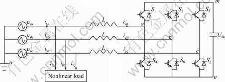
Fig.1 Structure of three-phase three-leg SAPF
The structure of a three-phase three-leg SAPF is shown in Fig.1, where L represents the equivalent inductance of the converter, Udc is the dc-link voltage value, and Si (i=1, 2, ��, 6) are the IGBT power semiconductors. The SAPF performs the function as a current source to generate compensation currents (icx (x=a, b, c)) which are expected to track the reference currents ![]() The compensation currents consist of harmonic and reactive power current isolated from load currents (ilx), but with reverse polarity. By injecting the compensation currents into power feeder, the source currents (isx) will be sinusoidal and in phase with the fundamental positive sequence mains voltages (ufx).
The compensation currents consist of harmonic and reactive power current isolated from load currents (ilx), but with reverse polarity. By injecting the compensation currents into power feeder, the source currents (isx) will be sinusoidal and in phase with the fundamental positive sequence mains voltages (ufx).
Most active power filters are designed based on the instantaneous reactive power algorithms. This algorithm is derived from the Park��s transformation, where the compensation current is calculated based on a two-axis system [4]. In their proposed method, mains voltage and load current are firstly transformed into two-axis representations. The instantaneous real power and the instantaneous imaginary power consumed by the loads are then calculated based on this representation system. After the compensation, the post-compensated current in the two-axis system is required to inversely transform back to the three-phase system; hence, the reference signals of compensation current are obtained. These reference signals and detected power converter output currents can be thus sent to a current controller to generate the pulse-width modulation (PWM) signals required for the operation of control circuits. By taking the ip-iq algorithm based on the instantaneous reactive power theory to detect the foundational positive sequence current for example, the principle diagram is shown in Fig.2.
In Fig.2, iaf, ibf and icf are the three-phase foundational positive currents; iah, ibh and ich are the differences between the three-phase load currents and foundational positive currents, which include harmonic and foundational positive currents; PLL (Phase Lock-Loop) is the phase lock-loop circuit, which is used to achieve the sinusoidal and cosine signals with the same frequency and phase as the main voltage of Phase A. The matrices C2/3 and C3/2 are stacked, given by
![]() (3)
(3)
![]() (4)
(4)
Supposing that the phase angle of the mains voltage of Phase A measured by PLL shown in Fig.2 is ![]()
![]() we can calculate C and C- as follows:
we can calculate C and C- as follows:
![]() (5)
(5)
By low pass filtering (LPF), the direct components of load currents ![]() and
and ![]() can be obtained as follows:
can be obtained as follows:
![]() (6)
(6)
And then, the three-phase foundational positive currents iaf, ibf and icf can be acquired by inverse transformation according to the ip-iq algorithm as
 (7)
(7)
Finally, the references current ixh can be obtained by the equation ixh=ixf-ixl, where x=a, b, c.
The detection results are independent of the initial phase of the voltage of Phase A according to Eq.(7). The three-phase foundational negative currents can also be achieved according to Fig.1 by simply modifying the matrices C2/3 and C3/2.
In some active filter systems which require reactive power compensation, the fundamental positive sequence active current components of load currents need to be isolated. However, we cannot obtain the foundational positive active currents and the foundational positive reactive currents accurately. When we cut off the ![]() channel in order to obtain the foundational positive active currents
channel in order to obtain the foundational positive active currents ![]()
![]() and
and ![]() Eq.(7) can be rewritten as
Eq.(7) can be rewritten as

 (8)
(8)
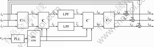
Fig.2 Principle diagram of ip-iq detection method
3 Reference current calculation and voltage prediction under non-ideal mains voltages
3.1 Modified ip-iq algorithm for reference current calculation
In order to accurately isolate the fundamental positive sequence active current from load current, phase information of the fundamental positive sequence components of mains voltages is definitely required. Figure 3 shows the principle diagram of the proposed reference current calculation method.
Here ![]() represents the positive sequence fundamental active current component which is isolated from three-phase load currents,
represents the positive sequence fundamental active current component which is isolated from three-phase load currents, ![]() represents the reference current, ufx is one of three-phase fundamental positive sequence voltages, and x=a, b, c. With the same expressions of ilx and usx in Eq.(1) and Eq.(2), the values of
represents the reference current, ufx is one of three-phase fundamental positive sequence voltages, and x=a, b, c. With the same expressions of ilx and usx in Eq.(1) and Eq.(2), the values of ![]() and
and ![]() are the same as Eq.(6), and the values of
are the same as Eq.(6), and the values of ![]() are given by
are given by
![]() (9)
(9)
According to Eq.(9), the three-phase fundamental positive sequence components of mains voltages can be obtained according to Fig.3 as follows:
 (10)
(10)
where ufx denotes the three-phase fundamental positive sequence mains voltage, and x=a, b, c. It will take function as reference information for fundamental positive sequence active currents in calculation process.
Here, a p-q rectangular coordinate shown in Fig.4 is introduced to illustrate the proposed method.
As shown in Fig.4, ![]() and
and ![]() (or
(or ![]() and
and ![]() ) are the coordinate values of vector I (or U).
) are the coordinate values of vector I (or U).
Definition 1: In the p-q rectangular coordinate system, the instantaneous positive sequence active current vector iu is the projection of vector I on vector U. The instantaneous positive sequence reactive current vector ![]() is the projection of vector I on the normal line of vector U. The coordinate values of vector I and U can be obtained from three-phase currents and voltages by p-q transformation defined as follows:
is the projection of vector I on the normal line of vector U. The coordinate values of vector I and U can be obtained from three-phase currents and voltages by p-q transformation defined as follows:
 (11)
(11)
The reverse p-q transformation from p-q rectangular coordinate values to three-phase currents and voltages is
 (12)
(12)
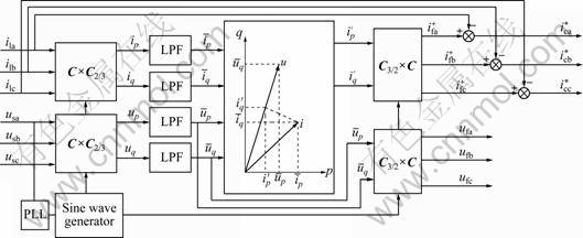
Fig.3 Principle diagram of proposed current reference isolation method
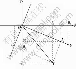
Fig.4 p-q rectangular coordinate
It can be seen from Eq.(5) and Eq.(6) that ![]()
![]() and
and ![]()
![]() are only composed of fundamental components, so the positive sequence active current vector iu only contains fundamental components. The p and q coordinate values
are only composed of fundamental components, so the positive sequence active current vector iu only contains fundamental components. The p and q coordinate values ![]() of vector iu can be obtained according to Definition 1 as follows:
of vector iu can be obtained according to Definition 1 as follows:
![]() (13)
(13)
The fundamental positive sequence active currents are isolated from the load currents according to Eq.(13). By performing reverse p-q transformation on ![]() we can get
we can get ![]() as follows:
as follows:

 (14)
(14)
By comparing Eq.(14) with Eq.(1), it is clear that![]() can represent the fundamental positive sequence active current component of load currents. Consequently, the three-phase reference currents
can represent the fundamental positive sequence active current component of load currents. Consequently, the three-phase reference currents ![]() (x=a, b, c) can be given by
(x=a, b, c) can be given by
![]() (15)
(15)
From above, it is known that the PLL in Fig.3 could be employed to measure the angular frequency of mains voltages, which has nothing to do with the phase angle. Hence, the PLL can be eliminated if the angular frequency has been known as a constant.
3.2 Closed-loop deadbeat control model of three- phase reference voltages
From Fig.1, Kirchnoff��s rules for voltages and currents applied at the connection point of SAPF allow one to write the three differential Eq.(16) in the stationary abc frame as follows:
 (16)
(16)
where usx is one of mains voltages, and uxo is one of the actual output voltages of the converter. Suppose that ![]() is one of the three-phase reference voltages, and
is one of the three-phase reference voltages, and ![]() is one of reference currents of SAPF which is calculated above, and then
is one of reference currents of SAPF which is calculated above, and then
 (17)
(17)
In order to implement digital control of SAPF within one control cycle labeled Tc, we discrete Eq.(12) into Eq.(13) as
![]() (18)
(18)
where k represents the beginning of the k-th control cycle. With the purpose to eliminate the delay error introduced from discrete control time interval, we consider to make use of predictive values ![]() to act as the target output voltages of the k-th control cycle. According to Eq.(18), we get
to act as the target output voltages of the k-th control cycle. According to Eq.(18), we get
![]() (19)
(19)
It is noted that the control cycle should be carefully chosen, as small as possible, to reduce the tracking error between ![]() and actual output voltages of the converter of SAPF. In this work, a voltage correction factor is introduced to reduce the accumulation of tracking error during every control cycle. By subtracting uxo in Eq.(18) from
and actual output voltages of the converter of SAPF. In this work, a voltage correction factor is introduced to reduce the accumulation of tracking error during every control cycle. By subtracting uxo in Eq.(18) from ![]() in Eq.(19), the correction factor ��uxo(k) can be obtained as
in Eq.(19), the correction factor ��uxo(k) can be obtained as
![]() (20)
(20)
Consequently, a closed-loop deadbeat control model of output reference voltages can be achieved as
![]()
![]() (21)
(21)
As ![]() and icx(k)=ilx(k)- isx(k), we can obtain the following equation:
and icx(k)=ilx(k)- isx(k), we can obtain the following equation:
![]()
![]() (22)
(22)
According to the one order Lagrange extrapolation theorem and the expressions of icx(k) and ![]() we can finally get the reference voltages of SAPF as follows:
we can finally get the reference voltages of SAPF as follows:
![]()
![]() (23)
(23)
4 Simulation result and field tests
The proposed control strategy is simulated under unbalanced and distorted mains voltages, and an experimental prototype based on a DSP controller is implemented for the purpose of testing of our strategy.
4.1 Simulation tests
The simulation model is built to compensate the source currents into the fundamental positive sequence active currents using the proposed control strategy. The mains voltages contain 3rd, 5th and 7th order harmonics with the ratios of 9.1%, 4.5% and 2.3%, respectively. The initial phase angles of three-phase mains voltages are 25��, -125�� and 120��. This means that the mains voltages are unbalanced. A three-phase thyristor rectifier is taken as typical nonlinear load. Sampling rate is set to be 10 kHz. Simulation results with constant and changing load are shown below.
4.1.1 Constant load
Figure 5 shows the mains voltages and load currents. It can be seen that both are quite nonsinusoidal containing a large amount of harmonic components.
Figure 6 shows the three-phase fundamental positive sequence mains voltages and the fundamental positive sequence active currents isolated by the proposed method. The PLL circuit in Fig.3 is eliminated during the simulation process. It can be seen from Fig.6 that the voltage and current waves are almost sinusoidal, and the isolated fundamental positive sequence active currents are in phase with the three-phase fundamental positive sequence mains voltages.
The simulation result of reference currents and the actual output compensation currents of Phase A are demonstrated in Fig.7.
In order to describe the similarity between the reference currents and the actual output compensation currents, here we introduce the definition of correlation coefficient.
Definition 2: By supposing x(n) and y(n) to be deterministic and causal signals with limited power, the correlation coefficient is defined as
![]() (24)
(24)

Fig.5 Three-phase mains voltages (a) and three-phase load currents (b)
Obviously, the APF shows better performance if the correlation coefficient value is large. By using sliding window method (window size: 200 sampling points), the correlation coefficient of the reference current and the actual output compensation current in Fig.7 can be calculated to be 0.988. The source current of Phase A before and after the SAPF being connected is shown in Fig.8. The total harmonic distortion (THD) of source current after compensation is 3.4% compared with 23.2% before compensation. The frequency spectrum of source current is shown in Fig.9 before and after compensation. It is clear that the odd harmonics have been reduced greatly after compensation.
4.1.2 Changing load
We change the dc-link resistance of the thyristor rectifier from 3 �� to 1.5 �� at 0.1 s. The fundamental positive sequence voltages and the fundamental positive sequence active currents are shown in Fig.10. The reference current and actual output compensation current of Phase A are shown in Fig.11. It can be seen from Fig.10 and Fig.11 that both the isolation method of reference current and the PWM control method can also reduce odd harmonics greatly and compensate reactive power effectively after compensation when the load changes.

Fig.6 Three-phase fundamental positive sequence voltages and fundamental positive sequence active currents isolated by proposed method: (a) Phase A; (b) Phase B; (c) Phase C
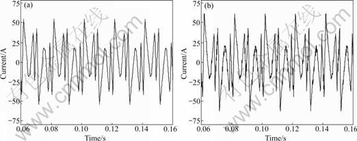
Fig.7 Simulation results of reference current (a) and compensation current (b) of Phase A
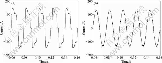
Fig.8 Source current of Phase A before compensation (a) and after compensation (b)

Fig.9 Frequency spectrum of source current before compensation (a) and after compensation (b)
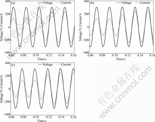
Fig.10 Three-phase fundamental positive sequence voltages and fundamental positive sequence active currents when load changes: (a) Phase A; (b) Phase B; (c) Phase C
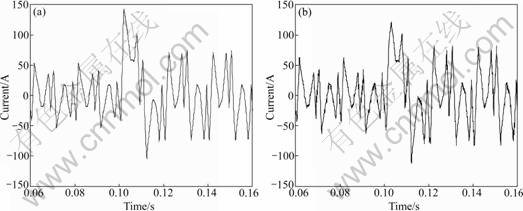
Fig.11 Reference current (a) and compensation current (b) of Phase A when load changes
The correlation coefficient value of reference current and output compensation current is calculated to be 0.986 after the load variation, as shown in Fig.12, which is a little smaller than the anterior correlation coefficient value of 0.988. This is because reference currents change faster after the load changing while the dc-link voltage of the converter keeps a constant. The source current of Phase A before and after compensation is shown in Fig.13. After the load is varied, the THD of source current is calculated to be 3.7% after compensation, smaller than 18.6% before compensation.
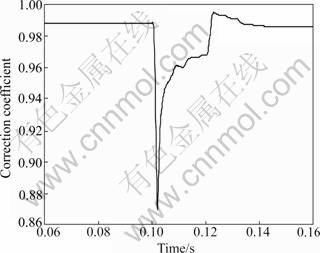
Fig.12 Correlation coefficient of reference current and actual output compensation current
4.2 Field application
An experimental prototype of SAPF is realized by the proposed control strategy, which consists of a three-phase voltage source converter based on IGBT power semiconductors. The IGBTs are controlled by switching pattern produced by the PWM controller. Harmonic isolator and PWM controller are implemented by a digital control board including a TSM320F2812 DSP controller. The switching frequency of power semiconductors is 10 kHz.
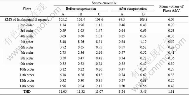
The experimental device is tested at a 10 kV substation. The local electrolysis manganese plant has injected a large amount of harmonics into the power system, especially the 5th, 7th, 11th and 13th order harmonics. Experimental results are shown in Fig.14, where CH2 is the load current of Phase A. CH3 is the source current after compensation. CH4 represents the output compensation current of Phase A. It could be found out easily that the harmonic components of the compensation current using Fourier analysis on CH4. Table 1 lists the harmonic contents before and after the SAPF being connected. It can be seen from Table 1 that the THD of source current is reduced from 11%-16% to 3%-4% after the SAPF being connected.
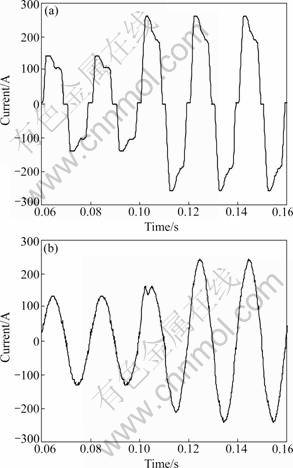
Fig.13 Source current of Phase A before compensation (a) and after compensation (b) when load changes

Fig.14 Experimental test results: M��Harmonic components of compensation current using FFT analysis on Ch4; 4��Output compensation current of Phase A; 3��Source current after compensation; 2��Load current of Phase A
5 Conclusions
1) The proposed reference current calculation method can isolate not only fundamental but also positive positive sequence active current components of the load currents under unbalanced and distorted mains voltages. Moreover, the PLL circuit can be eliminated when the angular frequency of mains voltage is a known constant, which simplifies the design of the current isolator.
Table 1 Experimental data
2) The deadbeat closed-loop model for output voltages of the converter shows good performances under non-ideal mains voltages. The correlation coefficient of reference currents and compensation currents can keep at a high level when the load changes. The proposed control method is very suitable for practical applications.
3) The source current is sinusoidal and in phase with the positive sequence fundamental voltages after compensation, which means that the SAPF is capable of performing harmonic cancellation and reactive power compensation under non-ideal mains voltages.
References
[1] EGUCHI K, OOTA I, TERADA S, INOUE T. A design method of switched-capacitor power converters by employing a ring-type power converter [J]. International Journal of Innovative Computing, Information and Control, 2009, 5(10A): 2927-2938.
[2] WANG Yan, MAO Zhi-zhong, TIAN Hui-xin, LI Yan, YUAN Ping. Modeling of electrode system for three-phase electric arc furnace [J]. Journal of Central South University of Technology, 2010, 17(3): 560-565.
[3] SINGH B, AL-HADDAD K, CHANDRA A. A review of active filters for power quality improvement [J]. IEEE Trans Ind Electron 1999, 46(5): 960-971.
[4] JAIN S, AGARWAL P, GUPTA H O. Design simulation and experimental investigations on a shunt active power filter for harmonics and reactive power compensation [J]. Electr Power Comp Syst, 2003, 32(7): 671-692.
[5] FURUHASSHI T, OKUMA S, UCHIKAWA Y. A study on the theory of instantaneous reactive power [J]. IEEE Trans Ind Electron, 1990, 37(1): 86-90.
[6] HU Zhi-ku, HU Meng-yang, GUI Wei-hua, YANG Chun-hua, HE Zhi-min. An improved ip-iq detection approach of positive fundamental active and reactive current based on p-q transformation [J]. Journal of Central South University: Science and Technology, 2010, 41(3): 1015-1021. (in Chinese)
[7] AKAGI H, KANAZAWA Y, NABAE A. Instantaneous reactive power compensator comprising switching devices without energy storage components [J]. IEEE Trans Ind Electron, 1984, 20(3): 625-630.
[8] AREDES M, HAFNER J, HEUMANN K. Three-phase four-wire shunt active filter control strategies [J]. Power Electronics, IEEE Transactions on, 1997, 12(2): 311-318.
[9] MA H, CAI Z. Comparison of control strategies for active power filter in three-phase four-wire systems [C]// The 30th Annual Conference of the IEEE Industrial Electronics Society. Busan, South Korea, 2004: 1429-1434.
[10] HUANG S, WU J, JOU H. A study of three-phase active power filters under nonideal mains voltages [J]. Electr Power Syst Res, 1999, 49(2): 129-137.
[11] KALE M, OZDEMIR E. An adaptive hysteresis band current controller for shunt active power filter [J]. Electr Power Syst Res, 2005, 73(2): 113-119.
[12] HUANG S J, WU J C. A control algorithm for three-phase three-wired active power filters under nonideal mains voltages [J]. IEEE Trans on Power Electron, 1999, 14(4): 753-760.
[13] KALE M, ?ZDEMIR E. Harmonic and reactive power compensation with shunt active power filter under nonideal mains voltage [J]. Electr Power Syst Res, 2005, 74(3): 363-370.
[14] SHIREEN W, TAO L. A DSP-based active power filter for low voltage distribution systems [J]. Electr Power Syst Res, 2008, 78(9): 1561-1567.
[15] MALESANI L, BUSO S. Robust dead-beat current control for PWM rectifiers and active filters [J]. IEEE Trans Ind App, 1999, 35(3): 613-620.
[16] LEE G M, LEE D C, SEOK J K. Control of series active power filters compensating for source voltage Unbalance and current harmonics [J]. IEEE Trans Ind App, 2004, 51(1): 132-139.
(Edited by YANG Bing)
Foundation item: Project(JC200903180555A) supported by Shenzhen City Science and Technology Plan, China
Received date: 2011-02-27; Accepted date: 2011-06-29
Corresponding author: HU Zhi-kun, Associate Professor, PhD; Tel: +86-731-88836335; E-mail: huzk@csu.edu.cn
Abstract: A novel control strategy for three-phase shunt active power filter (SAPF) was proposed to improve its performance under non-ideal mains voltages. The approach was inspired by our finding that the classic instantaneous reactive power theory based algorithm was unsatisfactory in terms of isolating positive sequence fundamental active components exactly under non-ideal mains voltages. So, a modified ip-iq reference current calculation method was presented. With usage of the new method, not only the positive sequence but also the fundamental active current components can be accurately isolated from load current. A deadbeat closed-loop control model is built in order to eliminate both delay error and tracking error between reference voltages and compensation voltages under unbalanced and distorted mains voltages. Computer simulation results show that the proposed strategy is effective with better tracking ability and lower total harmonic distortion (THD). The strategy is also applied to a 10 kV substation with a local electrolysis manganese plant injecting a large amount of harmonics into the power system, and is proved to be more practical and efficient.
