
J. Cent. South Univ. (2012) 19: 2477-2481
DOI: 10.1007/s11771-012-1299-4![]()
Evaluation of straightening capacity of plate roll straightener
WANG Yong-qin(������), LIU Zhi-fang(��־��), YAN Xing-chun(���˴�)
State Key Laboratory of Mechanical Transmission (Chongqing University), Chongqing 400044, China
? Central South University Press and Springer-Verlag Berlin Heidelberg 2012
Abstract:
Straightening machine is widely used for improving the quality of the defective mild steel plates. In general, the capacity of straightening machine is affected by material properties, the initial shape of the incoming plate and the plastic ratio. The mechanics model describing the capacity of the machine was developed. The deviation of the straightening capacity curves was studied. Then, the presented model was evaluated by comparative study to filed production data. Finally, the influences of overstretch, straightening speed, strengthening coefficient, elastic modulus, width of the plate on the straightening capacity were studied. It is convenient to determine whether the plate can be straightened or not by a series of straightening capacity curves. The straightening speed, width of the plate and elastic modulus of the material are more sensitive to the straightening capacity than the strengthening coefficient.
Key words:
plastic ratio; straightening capacity; strengthening factor; plate��
1 Introduction
Straightening is an important procedure in the production line of the plate. It is used to eliminate the common plate defections such as curl, gutter, middle waves and edge waves which are generated in the process of the rolling and cooling [1]. There are many reports on the straightening process prediction for a specific roll straightener. For example, Park and HWANG [2] and Huh et al [3] developed a FEM program for the analysis of roller straightening process and designed a FEM to calculate the quantitative level of curl, respectively. Behrens et al [4] developed an analytical 3D simulation model to find a suitable adjustment of the leveler to reach a flat sheet metal. Also, the analytic model had been studied to predict the curvature distribution in the thickness [5-9].
The equipment which can carry out this procedure is called the roll straighter. In connection with the expanded range of products made from plates and the increasingly stringent requirements on the quality of the plates, various modern straightening machines have been presented. Matsuzaki et al [10] studied a hot leveler which could be changed into a perfectly stable system by two dynamic absorbers by numerical analysis so that the polygonal wear of the rollers was not generated at all. Belobrov et al [11] and Titarenko et al [12] introduced the new modern straightening machines with world-class performance characteristics of the Novokramatorsky Mashinostroitelny Zavod (NKMZ) Company. Also, Belobrov et al [13] gave the main design features of the new in-line plate-straightening machines (PSMs) of the Severstal Company. In other words, the new generation straighteners have expanded the range of plate thicknesses, width and yield stress, automated the straightening operation, improved the reliability of the components and mechanisms, and reduced residual internal stresses in the plate.
The present work was focused on the process technology how to improve the residual stress and flatness of the plate well. But it is rare to have reports on the evaluation of the straightening capacity based on a detailed theoretical analysis for a specific roll straightener for a plate. For filling up this gap, it is necessary to study the basic principle of evaluating the capacity of the plate straightener. In this work, the mechanics model describing the strengthening capacity was presented. To verify the mechanics model, the results of proposed model were compared to the field production data. The factors affecting the capacity of the straightener were discussed by using the proposed model.
2 Capacity evaluation model of straightening process
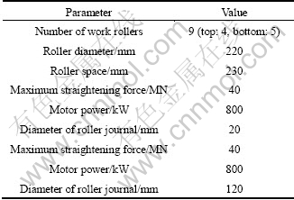
The new powerful straighter owns strong ability to level the extensive range plate, but the capacity of a specific leveler with the definite structure and power is limited. The straightener shown in Fig. 1 consists of nine, 220 mm-diameter rollers, with a separation between contiguous rollers of 230 mm. The lower rollers are fixed and certain vertical displacements are applied on the upper rollers. The maximum straightening force and the motor power are 40 MN and 800 kW, respectively. The equipment builder has supplied the design capacity and set for its machine for given materials, yield strength and thickness. In general, the capacity of a leveler is constrained by the following conditions.
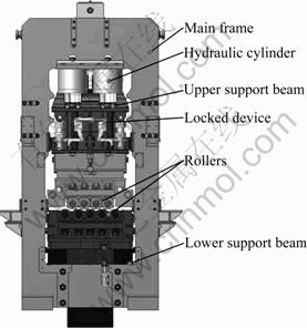
Fig. 1 3-D model of nine-roller leveler
2.1 Plastic ratio
The straightening process is very complicated with the elasto-plastic deformation in the plate. The percentage that the thickness of the plastic deformation accounts for the whole thickness is called the plastic ratio. The plastic ratio Rp, as shown in Fig. 2, is described as
![]() (1)
(1)
where Hp is the thickness of the plastic region and H is the total thickness of the plate.
The overstretch (S) is usually used to reflect the plastic ratio in the engineering. It is defined as
![]() (2)
(2)
The plastic ratio is an important parameter in the straightening technologies [14-15]. The quality of the plate can be improved well if Rp increases to 70%-80% (S=3.3-5). The plate cannot be leveled well if the plastic ratio is less than the expected value even though it is winded around the rollers (��=D/2). So the geometry model of overstretch can be summarized as
 (3)
(3)
where At is the elastic limit curvature, ![]() ��s,i is the yield stress of the plate, and D is the diameter of the rollers.
��s,i is the yield stress of the plate, and D is the diameter of the rollers.
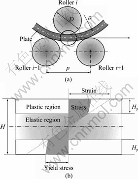
Fig. 2 Definition of overstretch
2.2 Maximum straightening force
The maximum force is a constant value when the straighter is designed over. So its straightening capacity is constrained by its maximum force and its structure. The straightening forces, as shown in Fig. 3, are generated by the rollers with the action of the roller gap. They can be deduced by the three-moment equation of multi-supported beam as
![]() (4)
(4)
where Mi-1, Mi and Mi+1 are the inner moments of the plate under roller i-1, i, i+1, respectively.
So, the sum straightening force is calculated as
![]() (5)
(5)
Equation (5) can be simplified as
 (6)
(6)
where N is the roll number, p is the roll pitch, Mt,i is the elastic limit inner moment of the plate under roller i, ![]()
![]() is the moment ratio,
is the moment ratio, ![]() , Mi is the inner moment of the plate under roller i, Fi is the straightening force of the plate under roller i, and Fsum is the maximum straightening force.
, Mi is the inner moment of the plate under roller i, Fi is the straightening force of the plate under roller i, and Fsum is the maximum straightening force.

Fig. 3 Straightening forces
2.3 Total motor power
Similar to the maximum straightening force, the total motor power is also a constant for a specific straighter. The torque that the transmission system needs to overcome includes the friction resisting moment at the roller journal, T1=F��(��d/2), the friction resisting moment between the roller and the plate, T2=F��(��d/2), and the
plastic deformation resisting moment, ![]() . So
. So
the relationship between the motor power and the inner moment can be summarized as
![]() (7)
(7)
where v is the straightening speed; uJ,i is the plastic energy in perlength of the plate;
![]() , ��i is the
, ��i is the
elastic ratio, and ![]() ; �� is the total efficiency of the transmission system; d is the diameter of the rollers journal; f is the coefficient of the rolling friction between the roller and the plate; �� is the friction coefficient between the roller journal and the bearing.
; �� is the total efficiency of the transmission system; d is the diameter of the rollers journal; f is the coefficient of the rolling friction between the roller and the plate; �� is the friction coefficient between the roller journal and the bearing.
So, Eq. (7) can be simplified as
![]()
![]() (8)
(8)
The parameters of Psum, D, p, d, ��, J and �� are constants for a definite straighter. The straightening force, the inner moment in the plate and the plastic energy in per length of the plate can be calculated according to the straightening process technology. All programs are carried out in Matlab software.
3 Verification
Using the in-house program, simulation results are obtained under the conditions listed in Table 1. It can be seen from Fig. 4 that the straightening capacities are a series of family curves. The greater the plastic ratio is, the narrower the straightening range is. Actually, any of the curves is surrounded by three parts. For example, as for the capacity curve of the case of S=3, Section B-C is controlled by the plastic ratio shown in Eq. (3), Section C-D is the maximum yield strength of all the plate, Section E-F is contained by the maximum straightening force and Section D-G is restricted by the motor power. Section E-F and Section D-G intersect at Point A. Finally, the straightening curve (S=3) is generated by the Section B-C, C-D, D-E and E-F.
Table 1 Straightening conditions of plate
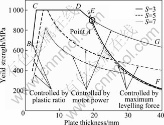
Fig. 4 Explanation of straightening capacity
In order to verify the proposed model, it is necessary to compare the results of the proposed model with some other credible data. It can be seen from Fig. 5 that the simulation result can match the field production result well. When S changes from 3 to 7 (plastic ratio changes from 66.7% to 85.7%), the straightening capacity changes obviously.
4 Discussion
The proposed model is used to research the influence of elastic modulus, strength coefficient and straightening speed on the straightening capacity. The straightening conditions are listed in Table 2.
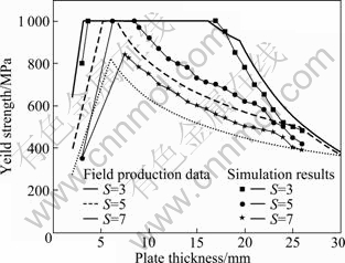
Fig. 5 Results comparison of proposed model and field production data
Table 2 Straightening conditions of plate
It can be found that the larger the straightening speed is, the narrower the range is in the same overstretch condition, as shown in Fig. 6. The plate (H=30 mm, ��s=800 MPa) located at point A, is above all the curves. This means that this plate is beyond the capacity of the straighter listed in Table 2 and it cannot be leveled in this straighter. Otherwise, the total straightening force or the total toque is larger than the allowable value of the machine. In other words, this straighter will be in danger. But if its yield strength decreases to 150 MPa, as shown at point A1, it can be leveled well. The plate (H=22 mm, ��s=700 MPa) located at point B is special because whether it can be leveled or not depends on its straightening speed and overstretch at the same time. If the straightening speed v=60 m/min and S=3.3 (Rp=70%), it can be leveled. But it is dangerous if v=120 m/min and S=5 (Rp=80%). In other words, whether it can be leveled depends on its straightening speed and defection degree. The plated located at point C (H=13 mm, ��s=500 MPa) is similar with that located at point B. Their difference is that the plate located at point C largely depends on overstretch. Contrast to the plate located at point A, the plate located at point D can be easily and safely leveled because it is below all the capacity curves.

Fig. 6 Straightening range under condition of B=3 000 mm, ��=0 and E=125 GPa
Considering the strengthen effect of the material, it is necessary to study the influence of strengthen coefficient on the straightening capacity. It can be found that the straightening capacity decreases to some degree when the material of the plates has the strengthening effect when comparing Fig. 6 with Fig. 7.
Also, the straightening capacity is influenced by elastic modulus and width of the plate. The greater the elastic modulus E is, the smaller the uJ,i is. So, the capacity shown in Fig. 8 is wider than that in Fig. 7.
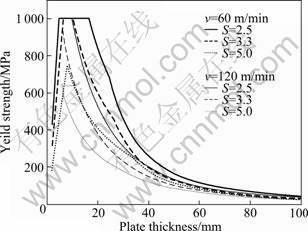
Fig. 7 Straightening range under condition of B=3 000 mm, ��=0.02 and E=125 GPa
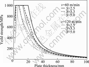
Fig. 8 Straightening range under condition of B=3 000 mm, ��=0.02 and E=210 GPa
Similarly, the capacity shown in Fig. 9 is wider than that in Fig. 8.
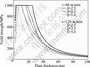
Fig. 9 Straightening range under condition of B=2 000 mm, ��=0 and E=125 GPa
5 Conclusions
1) The straightening capacity model is proposed and there is a good consistence when the simulation result is compared with the field production data.
2) The influence of overstretch, straightening speed, strengthening coefficient, elastic modulus, width of the plate on the straightening capacity is studied. The research results indicate that the greater the straightening speed, strengthening coefficient and width of the plate are, the smaller the straightening capacity is, and the larger the elastic modulus is, the larger the straightening capacity is.
3) The leveling possibility of a plate can be determined quickly and conveniently for a given shape and material properties.
Nomenclature

References
[1] TOMITA S, FUJITA Y. Recent trend and problems of straightening technologies of thick plates [J]. Journal of the Japan Society for Technology of Plasticity, 1999, 40: 408-11. (in Japanese)
[2] PARK K C, HWANG S M. Development of a finite element analysis program for roller straightening and application for removing blanking bow defects of thin steel sheet [J]. Iron & Steel Institute of Japan Journal, 2002, 42: 990-999.
[3] HUH H, LEE H W, PARK S R, KIM G Y, NAM S H. The parametric process design of tension straightening with an elasto-plastic finite element model [J]. Journal of Materials Processing Technology, 2001, 113: 714-719.
[4] BEHRENS B A, NADI T E, KRIMM R. Development of an analytical 3D-simulation model of the straightening process [J]. Journal of Materials Processing Technology, 2011, 211: 1060-1068.
[5] DOEGE E, MENZ R, HUININK S. Analysis of the straightening process based upon an analytic forming model [J]. Manufacturing Technology, 2002, 51: 191-194.
[6] Kadota K, Maeda R. A method of analysis of curvature in straightening process��numeric study of roller straightening process [J]. Journal of the Japan Society for Technology of Plasticity, 1993, 34: 481-486. (in Japanese)
[7] Higo T, Matsumoto H, Ogawa S. Effects of numerical expression of stress-stain curve on curvature of material of roller straightening process [J]. Journal of the Japan Society for Technology of Plasticity, 2002, 43, 496: 439-443. (in Japanese)
[8] XUE Jun-an, CUI Li, HU Xian-lei, LIU Xiang-hua. Effect of plastic deformation rate on plate steel during roller leveling [J]. Journal of Northeastern University, 2009, 5(5): 681-684. (in Chinese)
[9] CUI Li, HU Xian-lei, GUO Qiang, LIU Xiang-hua. Analyzing roller leveling strategies for high-strength steel plates [J]. Journal of Northeastern University, 2011, 32(5): 671-674. (in Chinese)
[10] MATSUZAKI K, SUEOKA A, RYU T, MORITA H. Generation mechanism of polygonal wear of work rolls in a hot leveler and a countermeasure by dynamic absorbers [J]. International Journal of Machine Tools & Manufacture, 2008, 48: 983-993.
[11] Belobrov Y N, Smirnov V G, Titarenko A I. Modern straightening machines [J]. Metallurgist, 2002, 46(9/10): 280-283.
[12] Titarenko A I, Belobrov Yu N, Smirnov V G, Evginenko I A, Shestopalov A V, Satonin A V, Satonin A A, Begunov A A. New advances at the Nvokramatorsk machine plant in the technology and equipment used for straightening plates [J]. Metallurgist, 2006, 50(11/12): 591-596.
[13] Belobrov Y N, Smirnov V G, Titarenko A I, Perekhodchenko V A, Sinel��nikov I L. Automating the Control of modern equipment for straightening flat-rolled products [J]. Metallurgist, 2004, 48 (7/8): 406-413.
[14] Matsuo A, Fujita M. Various problems in leveling the plates and sheets with roller leveling [J]. Iron & Steel Institute of Japan Journal, 2006, 19(2): 327-330. (in Japanese)
[15] Matsuo A, Yoshikazu S. Mechanism of roller leveling [J]. Iron & Steel Institute of Japan Journal, 2002, 15(5): 1010. (in Japanese)
(Edited by YANG Bing)
Received date: 2011-08-24; Accepted date: 2011-11-28
Corresponding author: WANG Yong-qin, Professor; Tel: +86-18908381890; E-mail: wyq@cqu.edu.cn
Abstract: Straightening machine is widely used for improving the quality of the defective mild steel plates. In general, the capacity of straightening machine is affected by material properties, the initial shape of the incoming plate and the plastic ratio. The mechanics model describing the capacity of the machine was developed. The deviation of the straightening capacity curves was studied. Then, the presented model was evaluated by comparative study to filed production data. Finally, the influences of overstretch, straightening speed, strengthening coefficient, elastic modulus, width of the plate on the straightening capacity were studied. It is convenient to determine whether the plate can be straightened or not by a series of straightening capacity curves. The straightening speed, width of the plate and elastic modulus of the material are more sensitive to the straightening capacity than the strengthening coefficient.
