
J. Cent. South Univ. Technol. (2011) 18: 1902-1909
DOI: 10.1007/s11771-011-0921-1![]()
A novel experimental system for performance evaluation of
water powered percussive rock drill
LI Xi-bing(��Ϧ��), LI Zhi-guo(��־��), ZHOU Zi-rong(������), LIU Xi-ling(��ϣ��)
School of Resources and Safety Engineering, Central South University, Changsha 410083, China
? Central South University Press and Springer-Verlag Berlin Heidelberg 2011
Abstract:
A set of water powered excavation test system was developed for the comprehensive performance testing and evaluation of water powered percussive rock drill indoors. The whole system contains hydraulic power section, electronic control system, test and data acquisition system, and assistant devices, such as guideway and drilling bench. Parameters of the water powered percussive rock drill can be obtained by analyzing testing data, which contain impact energy, front and back cavity pressure, pressure and flow in each working part, drilling velocity, frequency and energy efficiency etc. The system is applied to test the self-designed water powered percussive rock drill SYYG65. The parameters of water powered percussive rock drill with impact pressure of about 8.9 MPa are 58.93 J for impact energy, and 8.97% for energy efficiency, which prove the effectiveness of system.
Key words:
1 Introduction
With the increasing requirements of safety, environmental protection and energy saving and efficiency for excavation in deep rock mass engineering, the extensive attention and further study of water powered percussive rock drill development were aroused, which uses high pressure water instead of compressed air or mineral oil as working medium of percussive rock drill [1-3].
Some scholars studied the related problems of water powered percussive rock drill using some experimental devices [4-13]. Although these experimental devices can be used to study a specific component or technical problem, such as leakage of the impact device, friction, noise and efficiency, they can not be applied to test all performance parameters of the entire machine of water powered percussive rock drill synchronously. Furthermore, it is necessary for evaluation of performance parameters of water powered percussive rock drill system, improvement of percussive rock drill design, and the comparative research of traditional air and oil powered percussive rock drill.
Laboratory test is the most effective and economical method for comprehensive performance tests of the water powered percussive rock drill. It can avoid disadvantages of field drilling experiment such as large investment, long period, difficulties of data acquisition and many other interference factors.
The experimental system includes hydraulic power section, electronic control system, data acquisition system etc. Because there is no similar entire device in the world, the designation of this experimental system is mainly originated by test theory. Other experiences of water powered transmission test-bed [11-16] and oil powered rock drill test system [17] are used for reference to make sure that the system can be normally developed. Considering that the domestic components and processing technology can basically meet the technical requirements, this system is assembled mainly by domestic components except for the key components imported from the other countries, such as high pressure piston pump.
2 Test system of water powered excavation
The experimental system is used to simulate the power source of high pressure water generated by high fall between surface and underground working face, and the whole rock drilling process powered by high water potential energy. The system is mainly designed for water powered percussive rock drill, and it contains hydraulic power section, electronic control system, data acquisition system, and some other assistant devices such as guideway for sample machine and drilling bench. The control and power section of water powered excavation test system are shown in Fig.1, and the guideway and drilling bench are shown in Fig.2.
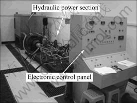
Fig.1 Control and power section of water powered excavation test system
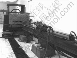
Fig.2 Guideway and drilling bench of water powered excavation test sysem
2.1 Test object of experimental system
The main test object of the experimental system is water powered percussive rock drill. The contents of test include impact stress in drill steel, pressure, water flow, impact frequency, displacement of percussive rock drill, rotational speed of the drill steel etc. The pressure is measured at the front and back cavity of the percussive rock drill, the inlet and outlet of the rock drilling circuit, the inlet detritus-removal circuit and the propulsion circuit; and the water flow is measured at the rock drilling circuit and dust-removal circuit. Based on the corresponding parameters above, the four systems of the water powered percussive rock drill: impact system, propulsion system, detritus-removal system and rotational system, were analyzed synchronously, and the impact frequency, impact energy and energy efficiency of the whole rock drill were also evaluated.
2.2 Hydraulic power section
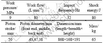
The hydraulic power section is used to simulate the power source of high pressure water generated by high fall between surface and underground working force, and to provide high-pressure hydro-energy for rock drill. The power section adopts open circuit consisting of three independent circuits: water powered rock drilling circuit, propulsion circuit and detritus-removal circuit which all share one water tank. Power configuration of each circuit and hydraulic parameters are shown in Table 1.
Table 1 Power configuration of each circuit and hydraulic parameters

2.2.1 Water powered rock drilling circuit
Water powered rock drilling circuit is shown in Fig.3. This circuit uses BMP8.0 high pressure piston pump (2) to supply water, and relief valve (unloading valve) (4) is installed at the outlet of pump. Highly pressured water is divided into two channels by two parallel connected on-off valves (6): one provides high-pressure to percussive rock drill, and the other unloads the returning pressure when percussive rock drill stops. Stop valve (10) paralleling connected with the circuit, is used to adjust the flow. Manometric joint (7), pressure gauge (9) and its switch, pressure sensor (8,11) are installed at the inlet side of the circuit to measure system pressure. Flowmeter (13) and the corresponding two-position three-port valve (12) are installed to measure the system water flow when needed. And the valve (12) is mounted at the end of the inlet side of the circuit to reserve a port for dust-removal experiment. In order to stablilize the pressure in the circuit, an accumulator (5) is installed behind relief valve in the return circuit.
2.2.2 Propulsion circuit
The CRI type low-pressure centrifugal water pump (14) is used to supply water for propulsion circuit (as shown in Fig.3), and the relief valve (unloading valve) (16) and manometric joint and pressure sensor (15) are installed at the outlet of the pump.
High-pressure water is divided into two channels by the dividing valve (17, UDOR): one supplies power for propulsion cylinder through two two-position four-port valve (18) in series (placed on an integrated block to form a three-position four-port valve); the other connecting with return circuit is used to adjust pressure and flow by the pressure regulating valve and the stop valve in the dividing valve. Because of the structure limitation, the working point of the centrifugal pump is changed by its performance curve. When the relief valve (unloading valve) pressure is initialized to be 2 MPa, the flow rate of the pump is 20 L/min. A water cylinder with 80 mm in inner diameter is used as propulsion cylinder in the circuit. The working parameters of the propulsion cylinder are: maximum propulsion: Fmax=0.785��82��20= 10.05 kN; maximum speed: Vmax=(20��103��0.785��82)�� 10-2=3.98 m/min. These parameters can meet the requirement of the propulsion system (Fmax��8 kN, Vmax> 1.2 m/min).
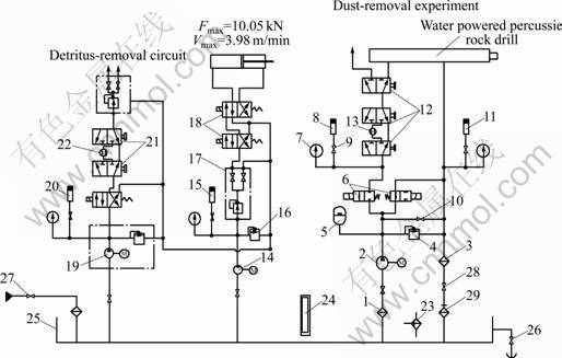
Fig.3 Schematic diagram of water powered system
2.2.3 Detritus-removal circuit
A cleaning pump (19) is used to supply water (shown in Fig.3), and its outlet is in parallel with the manometric joint and pressure sensor (20). The flowmeter (22) and the corresponding two-position three-port valve (21) are installed in the inlet of the detritus-removal circuit. High-pressure water is divided into two channels by the dividing valve (UDOR): one is used to clean detritus as the percussive rock drill is on operation, and the other is reserved for dust removal experiment. The flow and pressure of the high-pressure water can be changed by the pressure regulating valve and the stop valve, respectively.
2.2.4 Water tank
A stainless steel water tank is placed 1.5 m3 above the pump, as shown in Fig.3. Bottom of the water tank should be 0.6 m above the ground (higher than intake surface height) according to the requirement that the infall pressure of the high pressure piston pump (2) is 100-400 kPa (absolute pressure). The air filter (23) and sensor water-level gauge (24) are installed in the water tank and the release valve is in the lower part of the tank. To ensure the cleanliness of water, water tank provides water through stop valve (27) and magnetic backwater filter (29). The appropriate shutoff valves (26 and 27) are installed in the pump suction pipes in order to cut off water when the system is in reparation. A special self-sealing magnetic suction filter (1) is placed in suction port of the piston pump. Returned water in the rock drill circuit flows into water tank through the bag filter (3) and another magnetic backwater filter (29) in the tank, and the check valves (28) are installed in the backwater pipes of the water tank. Returned water (only a small part) of the propulsion circuit and the detritus- removal circuit directly discharge to ditch. Hydraulic power section is shown in Fig.1.
2.3 Electronic control system
Hydraulic power section is monitored and controlled by the electronic control system. The system includes water pump motor controller, electromagnetic valve controller, pressure monitor, flow monitor, filter resistance monitor and water level monitor.
The 45 kW high pressure piston pump motor is initiated by star-triangle reduced voltage, and the other two low-power motors are started directly. Considering the corrosion of water and the high pressure of the water powered rock drilling circuit, two imported GSR one-position two-port electromagnetic valves are used to compose a two-position two-port electromagnetic valve to control the circuit. The propulsion circuit is controlled by a three-position four-port electromagnetic valve formed by double two-position two-port electromagnetic valves. And the detritus-removal circuit is controlled by a two-position four-port electromagnetic valve individually. Five electromagnetic valves are used to control the on-off of water circuit and implement the forward, stop, and backward action of the propulsion cylinder. Control panel of the water powered excavation test set-up is shown in Fig.1.
Control panel is also fixed with some displayers and pilot lamp. The pressure data can be displayed by the four corresponding pressure displayers (220 V, AC power) connected to the pressure sensor used to monitor the pressure in inlet and outlet of the water powered rock drilling circuit, propulsion circuit and detritus-removal circuit. The flow data of the water powered rock drilling circuit are displayed by the digital displayer of the electronic water-meter (24 V, DC power) connected with the electronic water-meter sensor in the circuit. The flow data of the detritus-removal circuit is displayed by the turbine flow-meter (220 V, AC power) connected to the turbine flow-meter sensor. Some switches are set for the filter (water supply filter, water uptake filter, the outfall filter) in the water tank. When filter blocks, the resistance of the filter will be increased, and the switch junction is closed, then the corresponding pilot lamp is lightened for alarm. The level of the water tank is monitored by the sensor-based liquid level gauge connected with the pilot lamp on the control panel. When water level turns below the enactment value, the pilot lamp is lightened to alarm for the safety of the pump and the system.
2.4 Testing and data collection system
Testing and data collection system is mainly used in testing the impact energy of percussive rock drill, corresponding pressure and water flow, rock drilling velocity, impact frequency etc, and calculating energy efficiency of the system. All tests are designed according to corresponding standards [18-19].
The schematic diagram of the impact energy test system is shown in Fig.4, and the impact energy is measured using stress wave method. Two sets of strain gauges connected in series as one boom of the half-bridge are gived on both sides of the drill rod to test longitudinal wave. Voltage in the bridge circuit is input to XGC-E transient waveform recording analyzer after amplifying through YE3818C strain amplifier, and the incident stress waves are precisely captured in order, then the data are processed in computer after the analog signal is transformed to digital signal through an A/D converter. The data about the statistical values are collected for 25 times of maximum impact stress, impact energy and impact frequency. The impact energy can be calculated by the following equation:
![]() (1)
(1)
where e is the energy of the j-th stress wave; A is the sectional area of the drill rod with pasted strain gauges, m2; c is the velocity of the stress wave in drill rod, m/s; E is the elastic modulus of the rod, Pa; j is the number of integration points; Rj is the stress amplitudes of the number j integration point; ��t is the stress duration of each interval.
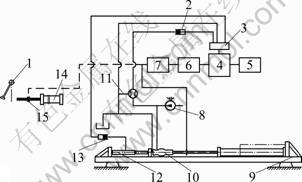
Fig.4 Impact energy test system: 1��Pendulum; 2��Pressure sensor and instrument; 3��A/D card; 4��Computer; 5��Printer; 6��Waveform recording analyzer; 7��Strain amplifier; 8��Pump station; 9��Drilling bench; 10��Rock drill; 11��Flowmeter; 12��Propulsion cylinder; 13��Pressure sensor and instrument; 14��Rod and energy absorber; 15��Strain gauge
As the electronic measurement system is influenced by different conditions, calibration is an important way to ensure measurement accuracy. Pendulum calibration is adopted to calibrate impact energy of this system (see Fig.4).
Due to the fact that the theoretical stress wave produced by pendulum impacting is hard to deduce, the calibration coefficients ![]() of the pendulum are modified by existing drop-hammer calibration equipment (the drop-hammer calibration method in Ref.[18]). According to stress calibration coefficients
of the pendulum are modified by existing drop-hammer calibration equipment (the drop-hammer calibration method in Ref.[18]). According to stress calibration coefficients ![]() and energy calibration coefficients
and energy calibration coefficients ![]() from the same measuring rod in drop-hammer experiment and pendulum experiment, the calibration factor K�� and KE can be obtained by the following equations:
from the same measuring rod in drop-hammer experiment and pendulum experiment, the calibration factor K�� and KE can be obtained by the following equations: ![]() and
and ![]() Then, put the value of K�� and KE in above equation, and revised equations are
Then, put the value of K�� and KE in above equation, and revised equations are ![]() and
and ![]() The calibrated coefficients
The calibrated coefficients ![]() and
and ![]() can be calculated. The mean values of five calibration experiments
can be calculated. The mean values of five calibration experiments ![]() and
and ![]() are selected as the formal calibration coefficients [18].
are selected as the formal calibration coefficients [18].
Diagram of water powered drilling test system is shown in Fig.5. Two pressure sensors are installed in the front and back cavity of the rock drill for measuring the pressure of two cavities. The intake pressure and outfall pressure of the impact system, the pressure of propulsion circuit, and the pressure of detritus-removal circuit are measured by the pressure sensors installed in the corresponding pipeline. Water flow of the impact system of the rock drill and the detritus-removal circuit is measured by the flowmeter installed in the corresponding pipeline. The rock-drilling velocity is detected by the timing software and the displacement sensor is installed on the guideway. Pressure signals fluctuated with piston motion are detected by the pressure sensor installed in the return circuit, and the impacting frequency can be calculated. The analog signals from upper sensors are amplified and rectified by the corresponding secondary instrument. And they are input into computer through A/D card in order that data sample and process can be output as graphics, saved, printed, inquired, and etc.
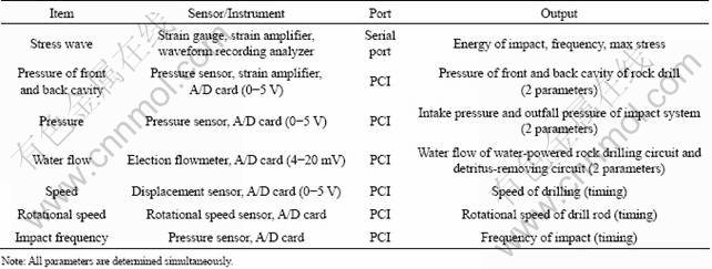
The pressure measurement system of water powered rock drillling circuit and propulsion circuit are calibrated by the precise pressure meter. The impact frequency is obtained from internal clock of the electronic measurement system. The AC6602L type A/D card with 16 channels is used in the electronic measurement system. Six channels are used to measure the intake and outfall pressure, pressure of propulsion and detritus- removal circuit, and pressure in the front and back cavity of the percussive rock drill; two are used to measure water flow of the water powered rock drilling circuit and detritus-removal circuit; three are used to measure the drill rod rotational speed, rock drilling velocity and impact frequency; another five channels are reserved for other measurements such as the pressure measurement in rotation circuit of the external rotation water powered percussive rock drill (see Table 2).
Then, the test system and data acquisition system are constructed. The function signal generator EE1641C is adopted to simulate and debug each testing channel, the system data acquisition precision and speed etc., to make sure that all the parameters meet the designing requirements.
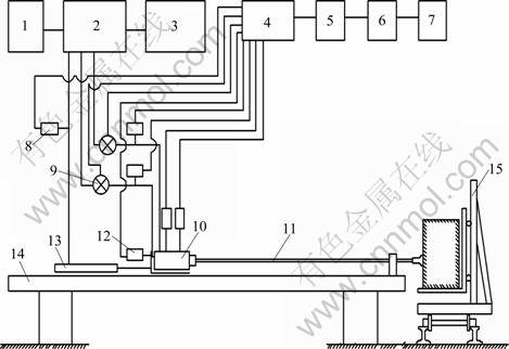
Fig.5 Water powered drilling test system: 1��Water tank; 2��Power station; 3��Control panel; 4��Secondary instrument; 5��Data acquisition card; 6��Computer; 7��Printer; 8��Pressure sensor; 9��Flowmeter; 10��Rock drill; 11��Drill rod; 12��Displacement sensor; 13��Propulsion cylinder; 14��Drilling bench; 15��Rock moving trolley
Table 2 Configuration of data acquisition system
3 Application of system
To verify the validity of this experimental system, parameters of rock drilling and impact performance of the SYYG65 are tested. Tests include pressure and flow of the impact system, outfall pressure of the impact system, pressure and flow of detritus-removal system, pressure of the propulsion circuit, rock drilling velocity, impact frequency and impact energy etc (see Fig.6).

Fig.6 Tests of water-powered percussive rock drill
Self-designed SYYG65 rail-guiding water powered percussive rock drill is shown in Fig.6 (arrow pointed), and the designing parameters are listed in Table 3. The B22 rod with 3 000 mm in rod length is used in this test on limestone.
3.1 Rock drilling test
Results of the rock drilling test are listed in Table 4. When impact pressure reaches 8.93-8.99 MPa, flow of the impact system is 114.8-116.2 L/min (higher than the designed one, 80 L/min), and the drilling velocity is 185-195 mm/min (less than that of similar hydraulic rock drill).
Table 3 Designing parameters of SYYG65
3.2 Impact performance test
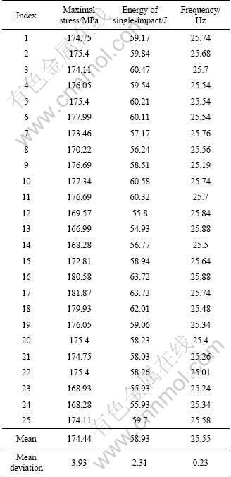
Pressure of impact system is set to be 8.911 MPa in this test. The tested outfall pressure is 0.279 MPa, and flow of impact system is 116.656 L/min. The incident stress wave in drill rod is continually collected 25 times. The 1st, 15th, 25th waveform of impact stress in drill rod is shown in Fig.7. Peak value, impact energy and impact frequency of all 25 stress waveforms are listed in Table 5.
Impact energy can be calculated by the methed based on Ref.[18], the mean value of impact energy of those 25 incident waves is 58.93 J, and the impact frequency is 25.55 Hz. Efficiency of the water powered percussive rock drill is 8.97% calculated by the software directly.
The curves in Fig.7 and the values in Table 5 show that the peak stress of all waves is higher than 168 MPa, the general rock compressive strength. The waveforms in Fig.7 also show that the higher stress lasts a long time during the impact process which benefits to rock breaking.
Table 4 Rock drilling test data

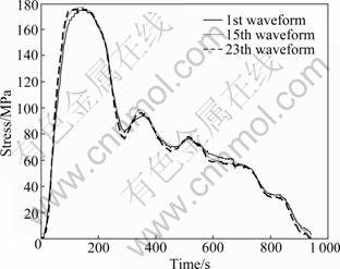
Fig.7 Typical waveform of impact stress in drill rod
Table 5 Impact energy test date
4 Conclusions
1) The water powered excavation test system contains hydraulic power section, electronic control system, test and data acquisition system, and assist devices including guideway and drilling bench etc.
2) The experimental system can be used to simulate deep high-pressure hydraulic environment, and can successfully drive the percussive rock drill SYYG65. The attributes of the water powered excavation implements such as water powered percussive rock drill and water powered down-the-hole hammer (DTH) can be measured directly and studied by this experimental set-up.
3) The impact pressure of this water powered percussive rock drill SYYG65 is about 8.9 MPa, the flow is about 116.6 L/min, the tested impact energy is 58.93 J, and the energy efficiency of the whole percussive rock drill is 8.97%, which indicates the feasibility of system.
4) The tested data of system also indicate that energy utilization ratio of the water powered percussive rock drill is low, and flow of the impact system is too large. This might be caused by the serious inside leakage of impact system. The design and processing technology should be improved. More comprehensive diagnosis should be analyzed by combining with other testing results such as the pressure of front and back cavity.
5) This experimental system can also provide high- pressure water power for some other hydraulic equipments such as high-pressure water-spraying dust suppression, high-pressure water-spraying cooling and hydraulic pressure prop.
References
[1] PARASZCZAK J, PLANETA S, OUELLET H. Comparative testing of water-powered and pneumatic jackleg rock drill [C]// SME Transactions Volume 296. California USA: University of California, 1995, 999-1002.
[2] ZHOU Zi-rong, LI Xi-bing, LIU Ying-chun. Research and experiment of water-powered rockdrill with supporting leg [J]. China Mechanical Engineering, 2004, 15(14): 1236-1239. (in Chinese)
[3] WU Xian-ming, LIU De-shun. The research and design of hydraulic-rock drill [J]. Machine Tool & Hydraulics, 2007, 35(4): 123-124. (in Chinese)
[4] ZHOU Zi-rong, PENG Hao-ke, ZENG Shu-lin. Research on the influence factors of leakage in annular clearance seals [J]. Lubrication Engineering, 2005(1): 7-9. (in Chinese)
[5] ZHOU Zi-rong, LI Xi-bing, LIU Ying-chun. Study and experiment on flow behavior of pressurized-water in annular micro-gaps [J]. 2005, 16(11): 1008-1012. (in Chinese)
[6] WU Xian-ming, LIU De-shun. Leakage and airproof of water pressure impact device [J]. Lubrication Engineering, 2002(6): 64-68. (in Chinese)
[7] ZHOU Zi-rong, LI Xi-bing, ZENG Shu-lin. Noise analysis and experimental study on water-powered impact rock drill [J]. Journal of Vibration and Shock, 2004, 23(4): 61-63. (in Chinese)
[8] ZHOU Zi-rong. Research on anti-erosion and anti-abrasion characteristics of impact piston materials for water-powered rock drills [J]. Construction Machinery and Equipment, 2004(12): 48-52. (in Chinese)
[9] ZHOU Zi-rong, ZENG Shu-lin, HU Zheng-xian, et al. QPQ combined salt bath treatment technology and its application to rock drills [J]. Construction Machinery and Equipment, 2003(10): 41-44. (in Chinese)
[10] WU Xian-ming, LIU De-shun. Experimental study on impact part structural form, axial thrust, rotation angle and rock drilling efficiency of water-power rock drill [J]. Journal of Vibration and Shock, 2007, 26(8): 154-157. (in Chinese)
[11] TUOMAS G.. Water powered percussive rock drilling process analysis modeling and numerical simulation [D]. Lule?, Sweden: Department of Civil and Environmental Engineering Lule? University of Technology, 2004: 6-15.
[12] TUOMAS G. Test bench for water powered DTH hammers [R]. Sweden: Lulea University of Technology, 2004.
[13] TUOMAS G. Effective use of water in a system for water driven hammer drilling [J]. Tunneling and Underground Space Technology, 2004, 19(1): 69-78.
[14] AI Qing-lin, ZHOU Hua, YANG Hua-yong. Data acquisition and processing of water hydraulic test rig [J]. Engineering Design, 2002, 9(2): 94-96.(in Chinese)
[15] YANG Shu-dong, HE Xiao-feng, LI Zhuang-yun, et al. Design and study of sea water hydraulic pump test standi [J]. Hydraulics & Pneumatics, 1997(6): 11-12. (in Chinese)
[16] YANG Shu-dong, YU Zu-yao, HE Xiao-feng, et al. Study on flippers for raw water hydraulic axial piston pumps and motors [C]// Proc of the 3rd Int Symposium on Fluid Power Transmission and Control. Beijing China: Int Academic Publish, 1999: 191-196.
[17] LIU Zhong, WU Jin-song, LI Wei. Research on testing principles & methods and experimental research on hydraulic impact machine [J]. China Mechanical Engineering, 2007, 18(15): 1769-1772. (in Chinese)
[18] Tianshui Research Institute of Rock Drilling Machines and Pneumatic tools. GB/T 5621��2008, Test methods of performance for rock drilling machines and pneumatic tools [S]. Beijing: Standards Press of China, 2008. (in Chinese)
[19] Research Institute of Mine Shaft Construction of China Coal Research Institute. MT/T 198-1996, General technical conditions of hydraulic rock drill used in coal mine [S]. Beijing: Standards Press of China, 1996. (in Chinese)
(Edited by DENG L��-xiang)
Foundation item: Project(2006AA06Z134) supported by the National High Technology Research and Development Program of China; Projects(50934006, 50904079) supported by the National Natural Science Foundation of China
Received date: 2010-06-29; Accepted date: 2011-03-11
Corresponding author: LI Xi-bing, Professor, PhD; Tel: +86-731-88836450; E-mail: xbli@mail.csu.edu.cn
Abstract: A set of water powered excavation test system was developed for the comprehensive performance testing and evaluation of water powered percussive rock drill indoors. The whole system contains hydraulic power section, electronic control system, test and data acquisition system, and assistant devices, such as guideway and drilling bench. Parameters of the water powered percussive rock drill can be obtained by analyzing testing data, which contain impact energy, front and back cavity pressure, pressure and flow in each working part, drilling velocity, frequency and energy efficiency etc. The system is applied to test the self-designed water powered percussive rock drill SYYG65. The parameters of water powered percussive rock drill with impact pressure of about 8.9 MPa are 58.93 J for impact energy, and 8.97% for energy efficiency, which prove the effectiveness of system.
