纳米SiC对AZ91D镁合金微弧氧化膜微观结构及性能的影响
来源期刊:中国有色金属学报(英文版)2015年第6期
论文作者:王淑艳 司乃潮 夏永平 刘莉
文章页码:1926 - 1934
Key words:magnesium alloy; micro-arc oxidation; nano-SiC; microstructure; property
摘 要:通过向Na2SiO3-NaAlO2复合电解液体系中添加纳米SiC,经过微弧氧化处理后在AZ91D镁合金表面制备含纳米SiC的复合陶瓷层。利用SEM、膜层测厚仪、XRD、EDS和维氏硬度计分别研究膜层的微观形貌、厚度、相结构、元素组成及硬度。采用摩擦磨损试验机对镁合金基体和膜层的干滑动磨损行为进行研究,运用动电位极化曲线试验和交流阻抗法测量镁合金基体和膜层在3.5% NaCl溶液中的耐蚀性能。结果表明:向电解液中添加纳米SiC后,微弧氧化的起弧电压和终止电压均下降。经纳米SiC复合处理后,微弧氧化膜层的孔径减小,致密性提高;与未添加纳米SiC的膜层相比,其厚度和硬度都得到提升,耐磨性与耐蚀性均增强。
Abstract: Ceramic coating incorporated with nano-SiC was obtained on AZ91D magnesium alloy during MAO by adding nano-SiC into the silicate-aluminate-based composite electrolyte. The microstructure, thickness, phase analysis, element composition and hardness of the coatings were respectively investigated by scanning electron microscopy(SEM), film thickness meter, X-ray diffraction (XRD), energy disperse spectroscopy(EDS) and Vickers hardness tester. The wear resistance of Mg alloy and coatings were evaluated by friction and wear apparatus, while the corrosion resistance of Mg alloy and coatings were evaluated by potentiodynamic polarization test and electrochemical impedance spectroscopy (EIS). The results show that after adding nano-SiC into the electrolyte, both the striking voltage and final voltage decrease, the size and number of the micropore on the surface of the coating decrease, the thickness and hardness of the coating increase, both the wear resistance and corrosion resistance of the coating raise.
Trans. Nonferrous Met. Soc. China 25(2015) 1926-1934
Shu-yan WANG1,2, Nai-chao SI1, Yong-ping XIA2, Li LIU2
1. School of Materials Science and Engineering, Jiangsu University, Zhenjiang 212013, China;
2. School of Materials Science and Engineering, Jiangsu University of Science and Technology, Zhenjiang 212003, China
Received 3 July 2014; accepted 25 March 2015
Abstract: Ceramic coating incorporated with nano-SiC was obtained on AZ91D magnesium alloy during MAO by adding nano-SiC into the silicate-aluminate-based composite electrolyte. The microstructure, thickness, phase analysis, element composition and hardness of the coatings were respectively investigated by scanning electron microscopy(SEM), film thickness meter, X-ray diffraction (XRD), energy disperse spectroscopy(EDS) and Vickers hardness tester. The wear resistance of Mg alloy and coatings were evaluated by friction and wear apparatus, while the corrosion resistance of Mg alloy and coatings were evaluated by potentiodynamic polarization test and electrochemical impedance spectroscopy (EIS). The results show that after adding nano-SiC into the electrolyte, both the striking voltage and final voltage decrease, the size and number of the micropore on the surface of the coating decrease, the thickness and hardness of the coating increase, both the wear resistance and corrosion resistance of the coating raise.
Key words: magnesium alloy; micro-arc oxidation; nano-SiC; microstructure; property
1 Introduction
Resources, energy and environmental issues are limiting the further development of human society. As the lightest structural metal in industrial applications, magnesium alloy has high specific strength and specific rigidity, good electrical and thermal conductivity, electromagnetic shielding, easy to be processed and easy to recycle, etc., it is known as the 21st century green engineering material [1]. However, the low corrosion resistance has impeded the widespread application of the magnesium alloy, so surface treatment is necessary. As a simple and environmental method of magnesium alloy, surface treatment, micro-arc oxidation(MAO) technology takes advantage of the instantaneous high temperature sintering effect in the micro-arc zone to form the ceramic coating on the surface of magnesium alloy, thereby improving the corrosion resistance and wear resistance of magnesium alloy [2,3]. The property of MAO coating is affected by many factors, including the composition of the electrolyte, the value of electrical parameter, etc [4-6]. The study of the electrolyte is mainly focused on the configuration of the basic electrolyte and the choice of additives. Adding different additives into the electrolyte can improve the relative properties of the coating as described in the literatures [7,8].
Due to some excellent properties, nanoparticles as a new kind of additive have caused the attention of many scholars in recent years. LI and LUAN [9] discovered that Al2O3 particles participated in the formation of MAO coating when adding Al2O3 particles into the aluminate electrolyte. YANG and LIU [10] found that the current density affected the MAO coatings embedded with SiC nanoparticles. These reports show that nanoparticles have effect on the MAO process, but there are few reports about the effect of nanoparticles on the property of MAO coating. Therefore, in this work, the influence of nano-SiC on the microstructure and properties of MAO coating was studied.
2 Experimental
2.1 Material
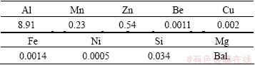
The material used in this experiment is the die-cast AZ91D magnesium alloy ingot. Its chemical composition is shown in Table 1.
The die-cast magnesium alloy ingot was cut into 15 mm × 15 mm × 5 mm bulk specimens, the specimens were ground with abrasive papers(with four grades: 300, 600, 1000, 1500) and then degreased by ultrasonic equipment before MAO treatment.
Table 1 Chemical composition of AZ91D die-cast magnesium alloy (mass fraction, %)
2.2 MAO treatment
MAO process was carried out with a WHD-20 MAO system which contained a stainless steel bath used as the negative electrode and magnesium alloy specimen used as the anode electrode, as well as a stirring and cooling system to keep the electrolyte temperature below 40 °C. The electrolyte was configured with distilled water. Na2SiO3 and NaAlO2 were the main coating-forming reagents in the electrolyte with a small amount of NaOH, C3H8O3, Na2B4O7 and C6H5Na3O7. Besides these, nano-SiC powders with the diameter of 40 nm were added into the electrolyte under ultrasonic condition. The electrolyte contained 15 g/L Na2SiO3, 9 g/L NaAlO2, 2 g/L Na2B4O7, 3 g/L NaOH, 5 mL/L C3H8O3, 7 g/L C6H5Na3O7 and 4 g/L nano-SiC. During the treatment, the electrolyte was stirred continuously in order to keep the nano-SiC in suspension.
Using the constant current control mode, setting the positive current density as 15 A/dm2, negative current density as 18 A/dm2, the pulse frequency as 520 Hz, positive duty cycle as 38%, negative duty cycle as 30%, the oxidation time as 15 min, MAO coatings were prepared under these conditions.
2.3 Specimen examination
The surface morphology of each MAO specimen and the worn surface of each specimen were observed by the JSM-6480 scanning electron microscope. All the MAO specimens were sprayed with a thin platinum film to make them conductive prior to SEM observation. The thickness of each MAO specimen was gauged by the CMI233 film thickness meter. The porosity of each MAO specimen was assessed by the ImageJ. The phase composition of the MAO specimen was examined by the XRD-6000 X-ray diffraction. The element composition of the MAO specimen was detected by the INCA energy disperse spectroscope. The hardness of each MAO specimen was measured by the MH-5 Vickers hardness tester. The friction and wear property of each specimen was investigated on the UMT-2 friction and wear apparatus. Electrochemical impedance spectroscopy (EIS) and potentiodynamic polarization tests were performed using the M283 electrochemical measurement system containing a potentiostat and a lock-in amplifier in 3.5% NaCl neutral solution at room temperature. The EIS measurements were made at open circuit potential (OCP) with AC amplitude of 10 mV and a frequency ranged from 105 Hz to 10-1 Hz. The potentiodynamic polarization tests were carried out with a scanning rate of 1 mV/s and a scanning range from -250 to 250 mV (vs OCP). Prior to tests, all the specimens were mounted by resin with 1 cm2 surface exposed, and coatings were immersed in the 3.5% NaCl neutral solution for 10 min to reach a stable potential. All electrochemical measurements were performed with a conventional three-electrode cell consisting of a platinum electrode as the counter electrode, a saturated calomel electrode as the reference electrode and MAO coatings as the working electrode.

Fig. 1 Voltage-time responses for microarc oxidation process
3 Results and discussion
3.1 Effect of nano-SiC on voltage of MAO process
The voltage-time responses of the MAO process with and without nano-SiC are shown in Fig. 1. It can be seen that the voltage-time responses of the MAO process followed the same trend with and without nano-SiC in the electrolyte. However, the addition of nano-SiC in the electrolyte slowed down the increase rate of the voltage. It was found that the MAO process can be divided into three stages according to the increasing rate of voltage. In the initial stage (stage I), voltage increased drastically with time at a high slope, and the increase-rate of voltage with and without nano-SiC in the electrolyte is almost the same. It can be considered that at the beginning of the experiment, the electrode was energized, and because of the deposition on the anode, a slight thin dielectric film immediately appeared on the surface of the specimen. Consequently, the resistance of the specimen increased and therefore the voltage increased rapidly. This process was called anodic oxidation. During this period, the electrolyte did not react with the substrate, so the addition of nano-SiC in the electrolyte had no influence on the change of voltage. In stage II, the voltage still increased with time, but the increase rate of voltage decreased obviously when compared with that in stage I. Furthermore, the increase rate of voltage with nano-SiC in the electrolyte was lower than that without nano-SiC in the electrolyte. The formation of dielectric film caused the increase of the voltage. When the voltage reached the striking voltage, it began with the MAO process. The growth of MAO coating is a process of multiple cycles: film formation→breakdown→melting→sintering→film formation again. The coating formation in this stage was a slow process of gradual growth and led to a slower increase rate of voltage when compared with stage I. After adding nano-SiC in the electrolyte and because of the vibration effect of ultrasonic, nano-SiC particles uniformly dispersed in the electrolyte. Moreover, because of relatively large surface energy of nano-SiC, they can absorb negative ions in the electrolyte [11] to form negatively charged colloidal particles. With the effect of the electric field, these colloidal particles moved toward the anode (magnesium alloy) and gathered on its surface, thereby hindered the discharge breakdown process of magnesium alloy, consequently slowing down the film growth rate. At the same time, the increase rate of voltage with nano-SiC in the electrolyte was lower than that without nano-SiC. In the final stage (stage III), the voltage increased more slowly when compared with the former two stages. In this stage, the coating was very thick and the breakdown of coating always occurred on the specific parts covered with a relatively thin coating. Thus, a slightly higher voltage was needed to maintain the stable current density, which led to a slow increase rate of voltage. In this stage, the voltage with nano-SiC in the electrolyte was still lower than that without nano-SiC.
The striking voltage and final voltage during MAO process are shown in Fig. 1. After adding nano-SiC in the electrolyte, both the striking voltage and final voltage decreased. Striking voltage decreased from 331 to 305 V while final voltage decreased from 457 to 434 V. The reason that the striving and final voltages with nano-SiC were lower than those without nano-SiC may be explained as Refs. [12,13]; however, it is important to provide more understanding in the future.
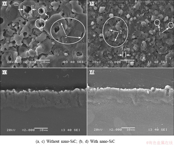
Fig. 2 Surface (a, b) and cross-sectional (c, d) morphologies of different MAO coatings
3.2 Effect of nano-SiC on morphologies of different MAO coatings
Figure 2 shows the surface and cross-sectional morphologies of different MAO coatings. It can be seen from Figs. 2(a) and (b) that MAO coatings showed a typical porous structure (marked by arrow 1), and there were several micro-cracks (marked by arrow 2) on the surface of the coatings. As shown in Fig. 2 (a), the surface of the coating obtained without nano-SiC showed several large volcanic-like micropores with the maximum diameter of the micropore up to 6 μm. These micropores were distributed unevenly on the surface and some micropores were blocked by the solidification of molten materials which ejected from the discharge channels. The excessive molten materials not only blocked the micropores but also formed a large connection area on the surface of the coating, as shown in the right bottom of the Fig. 2(a). In Fig. 2(b), the size of the micropores on the surface of the coating obtained with nano-SiC was smaller than that obtained without nano-SiC and the diameter of the micropores was less than 3 μm. At the same time, the number of the micropores on the surface of the coating with nano-SiC was less than that obtained without nano-SiC. After adding nano-SiC into the electrolyte, they adsorbed negative ions to form negatively charged colloidal particles which moved to the surface of the magnesium alloy. When the micro-arc discharged, the electrolyte in the discharge channels reacted with the magnesium alloy substrate and generated molten materials. Due to the high temperature and high pressure, the nano-SiC particles on the surface of the substrate were wrapped by the molten materials ejected from the channels. After solidification of the molten materials, nano-SiC and the molten materials became parts of the coating. However, the discharge time was short and the colloidal particles continuously moved toward the anode, so, a number of nano-SiC particles could not be wrapped in time and settled on the surface of the specimen [14]. Among them, there were some nano-SiC particles which settled in the discharge micropores, decreasing the diameter of the micropores and reducing the number of the micropores in the coating consequently improving the density of the coating. From Figs. 2(c) and (d), the coating obtained in the electrolyte with nano-SiC was relatively compact as compared with the coating in the electrolyte without nano-SiC (Fig. 2(c)), and many pores with big size existed in the coating.
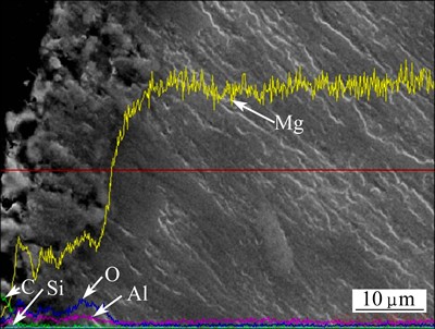
Fig. 3 Cross-sectional elements distribution of MAO coating with nano-SiC

Fig. 4 Thickness of different MAO specimens
Figure 3 represents the cross-sectional elements distribution of the MAO coating with nano-SiC detected by EDS. The concentration of Si in the whole coating was nearly constant, and the concentration of C on the surface of the coating was relatively higher than that in the middle of the coating. However, C exited in the whole coating may prove that the SiC participated in the MAO process.
3.3 Effect of nano-SiC on thickness and porosity of different MAO coatings
Figure 4 shows the thickness of different MAO coatings. The thickness of MAO coating with nano-SiC was higher than that without nano-SiC. This is due to the electrophoretic effect of nano-SiC. What is more, some nano-SiC particles were wrapped in the coating, and some were settled on the surface of the specimen. The synergistic effect between the two aspects increased the thickness of the coating. From Fig. 4, the thickness of different MAO coatings was very close. It differed just a few micrometers from each other. The additional SiC particles were at nano level, so they embedded into the inside and surface of the coating without obviously increasing the thickness of MAO coating.
The porosity of each MAO specimen can be assessed by the ImageJ and the pore processing maps of MAO coatings are shown in Fig. 5. It can be seen that the porosity of MAO coating diminished adding nano-SiC into the electrolyte. Moreover, CREUS et al [15] discovered that the porosity can be calculated with formula (1):
 (1)
(1)
where P is the porosity, Rps is the polarization resistance of the substrate, Rp is the polarization resistance of the coating, ΔEcorr is the corrosion potential difference of the coating and the substrate, ba is the anodic Tafel constant. According to the formula (1), the porosities of the coating with and without nano-SiC are respectively about 0.3% and 0.6%. This is due to the sedimentation of nano-SiC. It was explained in the Section 3.2.

Fig. 5 Pore processing maps of different MAO coatings
3.4 Effect of nano-SiC on phase composition of MAO coating
The X-ray diffraction pattern of the MAO coating obtained without nano-SiC is shown in Fig. 6. It can be concluded that the coating was mainly composed of MgO, MgAl2O4 and Mg2SiO4. The appearance of the diffraction peaks of Mg is a result of the coating being relatively thin and X-ray being able to penetrate through the coating to the substrate. The appearance of MgO, MgAl2O4 and Mg2SiO4 is the result of the reaction between Mg alloy substrate and the electrolyte.
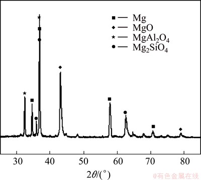
Fig. 6 XRD pattern of MAO coating without nano-SiC
Figure 7 shows the surface elemental mapping result of the MAO coating with nano-SiC. It can be seen that the coating was mainly composed of Mg, Al, O, Si and C. Each element distributed uniformly across the surface of the coating. In addition, it can be seen that the amount of Mg in the coating was the highest while the amount of C in the coating was the least. C in the coating came from nano-SiC, the little amount of C indicated that the content of nano-SiC in the coating was not large. The reason why nano-SiC appeared in the MAO coating can be explained as follows. Under the electrophoretic effect, the nano-SiC as the second phase particle involved in the deposition process, and part of the nano-SiC was wrapped by molten materials produced through micro-arc discharge, consequently, SiC became a part of the coating. It can also be seen in Fig. 3.
3.5 Effect of nano-SiC on hardness of MAO coating
Figure 8 shows the hardness of Mg alloy substrate as well as MAO specimens with and without nano-SiC. The result suggests that MAO can significantly improve the hardness of AZ91D Mg alloy after adding nano-SiC into the electrolyte, the hardness of MAO coating was further improved and about 20% higher than that of the coating without nano-SiC. This is due to the high strength and hardness of the nano-SiC. When nano-SiC was incorporated into the MAO coating, the hardness of the coating can be improved.
3.6 Effect of nano-SiC on wear resistance of MAO coating
The friction and wear experiments were carried out among Mg alloy substrate as well as the specimens with and without nano-SiC. The UMT-2 friction and wear apparatus was used in the experiment, the friction type was ball-block form of friction, and the GCr15 steel ball with 9 mm in diameter was used as the moving surface member. The dry sliding wear tests were carried out at the load of 10 N and a sliding speed of 30 rev/min with the wear diameter of 4 mm and the wear time of 15 min. The surface morphologies of wear tracks are shown in Fig. 9. It is obvious from Fig. 9 that the wear area of the coated specimen is smaller than that of the uncoated specimen. Furthermore, the wear area of the specimen obtained with nano-SiC is smaller than that without nano-SiC. The average coefficients of friction were 0.2512, 0.2287 and 0.1846, respectively, and their quality wear rates were 0.0333, 0.0267 and 0.0133 mg/min. It can be summarized that the addition of nano-SiC in the electrolyte can improve the wear resistance of the MAO coating.
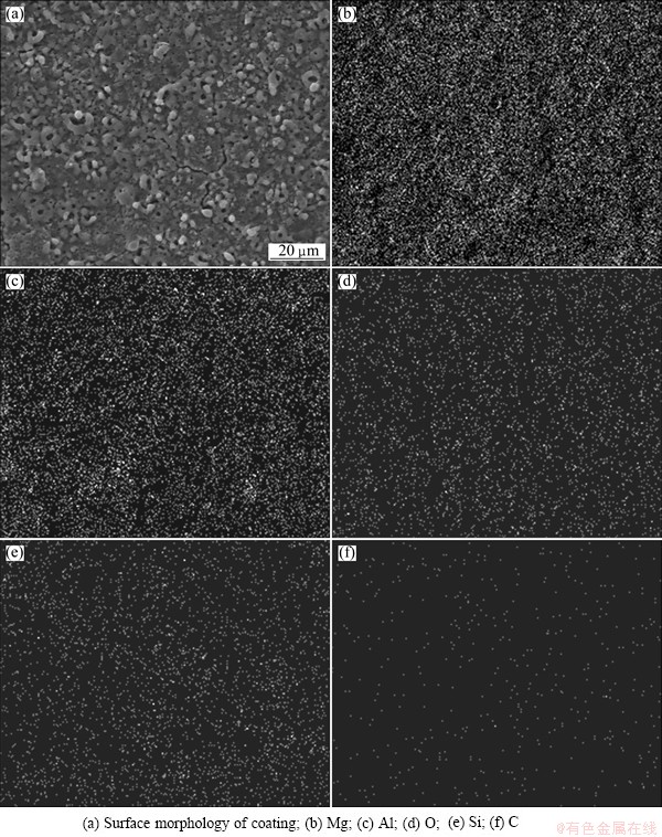
Fig. 7 Surface elemental mapping result of MAO coating with nano-SiC
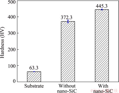
Fig. 8 Hardness of each specimen
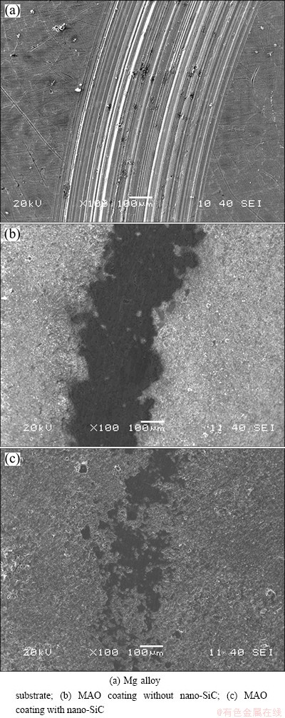
Fig. 9 Worn surface morphologies of specimens
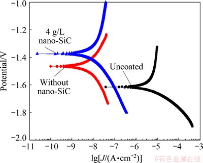
Fig. 10 Polarization curves of specimens
3.7 Effect of nano-SiC on corrosion resistance of MAO coating
3.7.1 Potentiodynamic polarization test
The corrosion resistances of the Mg alloy substrate and MAO specimens with and without nano-SiC were studied by potentiodynamic polarization technique in 3.5% NaCl solution at room temperature (Fig. 10). The parameters related to the corrosion resistance such as corrosion potential (φcorr), corrosion current density (Jcorr), anodic Tafel constant (ba) and cathodic Tafel constant (bc) can be obtained from the polarization curve by the method of Tafel region extrapolation. The polarization resistance (Rp) can be calculated with the formula (2), which called the Stern-Geary equation [16]. All the parameters are summarized in Table 2.
 (2)
(2)
φcorr, Jcorr and Rp are the three important parameters to evaluate the corrosion resistance of the coating. High φcorr, low Jcorr and high Rp indicate a good corrosion resistance of the coating. It can be seen from Table 2 that the three parameters of the coated specimens were all better than those of the uncoated specimen. Especially, the corrosion current densities of the coated specimens decreased three orders of magnitude when compared with the uncoated specimen. For the specimen obtained with nano-SiC, the corrosion potential moved toward the positive direction by about 86 mV when compared with that without nano-SiC. The polarization resistance of the specimen with nano-SiC was 18.7% larger than that obtained without nano-SiC. These results show that the incorporation of nano-SiC can improve the corrosion resistance of the coating. The reason for this phenomenon can be attributed to the dense structure of the composite coating which provided a good barrier to prevent the penetration of chloride ions.
Table 2 Fitted electrochemical parameters from polarization curves

3.7.2 Electrochemical impedance spectroscopy test
Figure 11 represents the electrochemical impedance spectroscopy plots of uncoated and coated specimens with and without nano-SiC. The radius of the capacitive loop reflects the corrosion resistance of the coating. The bigger the radius of capacitive loop, the better the corrosion resistance of the coating.
As shown in Fig. 11(a), the coated specimens showed larger capacitive loops than the uncoated specimen, and the radius of capacitive loop was enlarged with the addition of nano-SiC in the electrolyte. This was an aspect to prove that the incorporation of nano-SiC can improve the corrosion resistance of the coating. The appearance of inductive loop in the uncoated specimen indicated that the corrosive medium (Cl-) had already induced the corrosion of the substrate, which proved that pitting occurred on the surface of magnesium substrate. In Fig. 11(b), the impedance of the uncoated specimen was 374 Ω・cm2 at the frequency of 0.1 Hz, whereas the impedance of the coated specimen was 131951 and 811160 Ω・cm2 respectively at the frequency of 0.1 Hz. This indicates that MAO can improve the corrosion resistance of the AZ91D Mg alloy, and the incorporation of nano-SiC can further improve the corrosion resistance of the coating. The results obtained from Fig. 11 are consistent with those in Fig. 10.
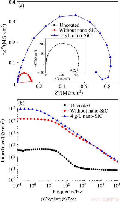
Fig. 11 EIS plots of Mg alloy substrate and coated specimen with and without nano-SiC
4 Conclusions
1) Both the striking voltage and final voltage decrease after adding nano-SiC into the electrolyte.
2) The porosity of the MAO coating can be reduced and the density of the MAO coating can be increased by adding nano-SiC into the electrolyte.
3) Both the thickness and hardness of the MAO coating increase after adding nano-SiC into the electrolyte.
4) The friction coefficient of the coating decreases and the wear rate reduces, at the same time, the wear resistance improves when compared with the coating obtained without nano-SiC.
5) The impedance of MAO coating increases while the corrosion potential moves toward the positive direction, the corrosion resistance of the coating improves after adding nano-SiC into the electrolyte.
References
[1] DING Wen-jiang. Science and technology of magnesium alloy [M]. Beijing: Science Press, 2007: 25-26. (in Chinese)
[2] LIM T S, RYU H S, HONG S H. Electrochemical corrosion properties of CeO2-containing coatings on AZ31 magnesium alloys prepared by plasma electrolytic oxidation [J]. Corrosion Science, 2012, 62: 104-111.
[3] LU Wei-ling, CHEN Ti-jun, MA Ying, XU Wei-jun, YANG Jian, HAO Yuan. Effects of increase extent of voltage on wear and corrosion resistance of micro-arc oxidation coatings on AZ91D alloy [J]. Transactions of Nonferrous Metals Society of China, 2008, 18: s354-s360.
[4] YAGI S, SENGOKU A, KUBOTA K, MATSUBARA E. Surface modification of ACM522 magnesium alloy by plasma electrolytic oxidation in phosphate electrolyte [J]. Corrosion Science, 2012, 57: 74-80.
[5] HWANG I J, HWANG D Y, KO Y G, SHIN D H. Correlation between current frequency and electrochemical properties of Mg alloy coated by micro arc oxidation [J]. Surface and Coatings Technology, 2012, 206: 3360-3365.
[6] CHENG Ying-liang, WU Xiang-quan, XUE Zhi-gang, MATYKINA E, SKELDON P, THOMPSON G E. Microstructure, corrosion and wear performance of plasma electrolytic oxidation coatings formed on Ti-6Al-4V alloy in silicate-hexametaphosphate electrolyte [J]. Surface and Coatings Technology, 2013, 217: 129-139.
[7] PAN Y K, CHEN C Z, WANG D G, YU X, LIN Z Q.Influence of additives on microstructure and property of microarc oxidized Mg-Si-O coatings [J]. Ceramics International, 2012, 38: 5527-5533.
[8] LIU Ya-juan, XU Jin-yong, GAO Ying, YUAN Ye, GAO Cheng. Influences of additive on the formation and corrosion resistance of micro-arc oxidation ceramic coatings on aluminum alloy [J]. Physics Procedia, 2012, 32: 107-112.
[9] LI Xi-jin, LUAN Ben-li. Discovery of Al2O3 particles incorporation mechanism in plasma electrolytic oxidation of AM60B magnesium alloy [J]. Materials Letters, 2012, 86: 88-91.
[10] YANG Yue, LIU Yao-hui. Effects of current density on the microstructure and the corrosion resistance of alumina coatings embedded with SiC nano-particles [J]. Journal of Materials Science and Technology, 2010, 26(11): 1016-1020.
[11] YANG Shi-kuan, CAI Wei-ping, ZENG Hai-bo, XU Xiao-xia. Ultra-fine β-SiC quantum dots fabricated by laser ablation in reactive liquid at room temperature and their violet emission [J]. Journal of Materials Chemistry, 2009, 19: 7119-7123.
[12] ARRABAL R, MATYKINA E, SKELDON P, THOMPSON G E. Incorporation of zirconia particles into coatings formed on magnesium by plasma electrolytic oxidation [J]. Journal of Materials Science, 2008, 43: 1532-1538.
[13] LALEH M, ROUHAGHDAM A S, SHAHRABI T, SHANGHI A. Effect of alumina sol addition to micro-arc oxidation electrolyte on the properties of MAO coatings formed on magnesium alloy AZ91D [J]. Journal of Alloys and Compounds, 2010, 496: 548-552.
[14] YANG Yue, CHEN Bin. Effects of SiC nano particles on microstructure and the corrosion resistance of micro arc oxidation films produced on 6060 aluminum alloy [J]. Journal of Jilin University: Engineering and Technology Edition, 2011, 41(S1): 106-110. (in Chinese)
[15] CREUS J, MAZILLE H, IDRISSI H. Porosity evaluation of protective coating onto steel, through electrochemical techniques [J]. Surface and Coating Technology, 2000, 130: 224-232.
[16] LEE K M, SHIN K R, NAMGUNG S, YOO B Y, SHIN D H. Electrochemical response of ZrO2-incorporated oxide layer on AZ91 Mg alloy processed by plasma electrolytic oxidation [J]. Surface and Coating Technology, 2011, 205: 3779-3784.
王淑艳1,2,司乃潮1,夏永平2,刘 莉2
1. 江苏大学 材料科学与工程学院,镇江 212013;
2. 江苏科技大学 材料科学与工程学院,镇江212003
摘 要:通过向Na2SiO3-NaAlO2复合电解液体系中添加纳米SiC,经过微弧氧化处理后在AZ91D镁合金表面制备含纳米SiC的复合陶瓷层。利用SEM、膜层测厚仪、XRD、EDS和维氏硬度计分别研究膜层的微观形貌、厚度、相结构、元素组成及硬度。采用摩擦磨损试验机对镁合金基体和膜层的干滑动磨损行为进行研究,运用动电位极化曲线试验和交流阻抗法测量镁合金基体和膜层在3.5% NaCl溶液中的耐蚀性能。结果表明:向电解液中添加纳米SiC后,微弧氧化的起弧电压和终止电压均下降。经纳米SiC复合处理后,微弧氧化膜层的孔径减小,致密性提高;与未添加纳米SiC的膜层相比,其厚度和硬度都得到提升,耐磨性与耐蚀性均增强。
关键词:镁合金;微弧氧化;纳米SiC;微观结构;性能
(Edited by Xiang-qun LI)
Foundation item: Project (12504230006) supported by the Priority Academic Program Development of Jiangsu Higher Education Institutions, China
Corresponding author: Shu-yan WANG; Tel: +86-511-84426291; E-mail: wsy101010@126.com
DOI: 10.1016/S1003-6326(15)63800-6

