A novel non-overlapping approach to accurately represent 2D arbitrary particles for DEM modelling
来源期刊:中南大学学报(英文版)2017年第1期
论文作者:孟庆祥 ZHANG Qiang(张强) XU Wei-ya(徐卫亚) 刘沁雅 王伟
文章页码:190 - 202
Key words:discrete element method (DEM); composite approaches; arbitrary particles; clusters; non-overlapping disks
Abstract: Mechanical behaviors of granular materials are complicated and greatly influenced by the particle shape. Current, some composite approaches have been proposed for realistic particle shape modelling within discrete element method (DEM), while they cannot give a good representation to the shape and mass properties of a real particle. In this work, a novel algorithm is developed to model an arbitrary particle using a cluster of non-overlapping disks. The algorithm mainly consists of two components: boundary filling and domain filling. In the boundary filling, some disks are placed along the boundary for a precise representation of the particle shape, and some more disks are placed in the domain to give an approximation to the mass properties of the particle in the domain filling. Besides, a simple method is proposed to correct the mass properties of a cluster after domain filling and reduce the number of the disks in a cluster for lower computational load. Moreover, it is another great merit of the algorithm that a cluster generated by the algorithm can be used to simulate the particle breakage because of no overlaps between the disks in a cluster. Finally, several examples are used to show the robust performance of the algorithm. A current FORTRAN version of the algorithm is available by contacting the author.
J. Cent. South Univ. (2017) 24: 190-202
DOI: 10.1007/s11771-017-3420-1

ZHANG Qiang(张强)1, 2, 3, XU Wei-ya(徐卫亚)1, 2, LIU Qin-ya(刘沁雅)3,
WANG Wei(王伟)1, 2, MENG Qing-xiang(孟庆祥)1, 2, 4
1. Key Laboratory of Ministry of Education for Geomechanics and Embankment Engineering,
Hohai University, Nanjing 210098, China;
2. Research Institute of Geotechnical Engineering, Hohai University, Nanjing 210098, China;
3. Department of Physics, University of Toronto, Toronto, M5S 1A7, Canada;
4. Department of Civil & Environmental Engineering, University of Waterloo, Waterloo, N2L 3G1, Canada
 Central South University Press and Springer-Verlag Berlin Heidelberg 2017
Abstract: Mechanical behaviors of granular materials are complicated and greatly influenced by the particle shape. Current, some composite approaches have been proposed for realistic particle shape modelling within discrete element method (DEM), while they cannot give a good representation to the shape and mass properties of a real particle. In this work, a novel algorithm is developed to model an arbitrary particle using a cluster of non-overlapping disks. The algorithm mainly consists of two components: boundary filling and domain filling. In the boundary filling, some disks are placed along the boundary for a precise representation of the particle shape, and some more disks are placed in the domain to give an approximation to the mass properties of the particle in the domain filling. Besides, a simple method is proposed to correct the mass properties of a cluster after domain filling and reduce the number of the disks in a cluster for lower computational load. Moreover, it is another great merit of the algorithm that a cluster generated by the algorithm can be used to simulate the particle breakage because of no overlaps between the disks in a cluster. Finally, several examples are used to show the robust performance of the algorithm. A current FORTRAN version of the algorithm is available by contacting the author.
Key words: discrete element method (DEM); composite approaches; arbitrary particles; clusters; non-overlapping disks
1 Introduction
Discrete element method (DEM) was initially developed by CUNDALL and STRACK [1] to model the mechanical behavior of granular materials and the past 30 years has witnessed extensive application in the field of geotechnical engineering [2]. In DEM, granular materials are considered as an assembly of primitives interacting with each other based on a contact law. For easy implementation of contact detection and time-saving, primitives are simplified initially as disks in 2D without considering the real shape of the particles (Fig. 1(b)). However, one of the unique features of a real particle is its irregular shape (Fig. 1(a)), which has a significant influence on the mechanical behaviors of particle systems [3, 4]. Some attempts towards realistic particle shape modeling have been made to improve the result of simulations [5]. Many methods to model the real shape of particulate materials have been presented in scientific literatures, which can be divided into two categories: 1) new primitive methods, 2) composite methods.
New primitive methods are that non-circular primitives are directly implemented in DEM to model real particles. For example, ellipse-shaped primitives [6] (Fig. 1(c)), polygon-shaped primitives [7], super- quadrics [8], and arbitrary shape primitives using discrete function representations [9] have been implemented successfully in the DEM modelling to improve the simulation results. The main merit of these methods is that a real particle can be only modeled by a primitive. However, these proposed primitives can only give a coarse approximation to the real particle shape. Although more complex primitives can be proposed for an accurate representation of the particle shape, robust and efficient algorithms need to be developed accordingly for contact detection and force calculation, leading to deterioration of computational efficiency in the simulations [9].
Composite methods are based on a thought that an arbitrary particle is represented by combining some disks into a cluster of similar shape as a rigid body [10, 11], as shown in Figs. 1(d) and (e). These methods have a common advantage that contact detection and force calculation are based on the simple algorithms valid for disks and are therefore very efficient and robust [12]. This idea has been widely used to model a real particle within DEM since proposed by JENSEN et al [13], and it has also been implemented in common DEM-packages such as PFC2D and PFC3D [14, 15]. According to whether or not overlaps exist between the disks in a cluster, these composite methods are classified into two categories: overlapping approaches (Fig. 1(d)) and non-overlapping approaches (Fig. 1(e)), which will be presented in details in section 2. However, these composite methods cannot give a good representation to the shape and mass properties of a real particle.
In this work, after making a detailed review of some DEM modeling methods in literatures and a discussion of their advantages and disadvantages (Section 2), a novel non-overlapping algorithm which is regarded as a variant of an available method proposed by LIU et al [16] to generate a packing for DEM is developed to simulate a real particle in DEM modelling. The cluster generated by this novel algorithm can give an accurate representation of a real particle in terms of the shape and mass properties.
2 Current composite methods to represent irregular particles for DEM
As mentioned above, composite methods can be divided into two categories: overlapping approaches and non-overlapping approaches. For non-overlapping approaches, no overlaps exist between the disks in a cluster, as shown in Fig. 1(c). The disks are allowed to overlap in order to give a better description of particle shape for overlapping approaches with small number of disks, as shown in Fig. 1(d). In the following, a detail introduction and discussion of current composite methods are presented.
2.1 Non-overlapping approaches
In the simplest form of non-overlapping approaches, some disks with different radii are manually clumped together to give a coarse approximation to the particle shape. As shown in Fig. 2, the radii and positions of the disks in the clusters are determined manually based on the shapes of different particles. It is not an advisable method to generate clusters for a large number of particles because it is very time-consuming.
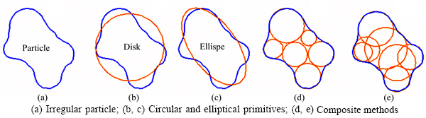
Fig. 1 Methods of particle representation for DEM modelling:
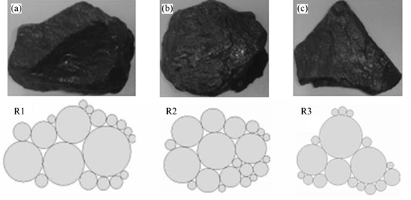
Fig. 2 Illustration of a non-overlapping approach in Ref. [17] to generate clusters for three particles (R1 (a), R2 (b) and R3 (c))
In order to investigate the effect of stone content on the mechanical behavior of outwash deposits, a non- overlapping method was proposed by WANG et al [18] to generate clusters for stones. As shown in Fig. 3, the process of generation of a cluster for a stone mainly includes two steps: a regular domain bigger than that of a stone is filled by some disks using the packing algorithm for DEM firstly (Figs. 3(a) and (b)), then all disks whose central positions are located inside of the outline of the stone are clumped together as a cluster (Figs. 3(c) and (d)). In this way, the generated cluster gives a coarse representation of a stone. Generally speaking, more accurate description can be achieved by larger number of dishes with smaller sizes.
2.2 Overlapping approaches
The core idea of overlapping approaches is that the arbitrary shape can be described more accurately with small number of disks by allowing the overlap. WANG et al [19] presented an algorithm (Burning algorithm) where the irregular domain of a real particle is filled with a regular arrangement of small disks and afterwards an optimization is made by replacing a group of adjacent disks by a bigger one, as shown in Fig. 4(a). The purpose of the substitution of the small disks is to reduce the number of disks and the computational load later in DEM simulations. Though the outline of the cluster generated by the algorithm captures the gross shape of the real particle, it can only give relatively rough representation for the shape of sharp particles. In order to give a closer approximation to the particle shape, a clustered overlapping sphere (COS) algorithm was proposed by GARCIA et al [20], which was regarded as an extension of the Burning Algorithm, as shown in Fig. 4(b). By allowing overlaps between the disks, the algorithm can generate a cluster consists of relatively modest number of disks to represent a real particle with acceptably short computational load.
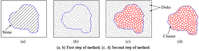
Fig. 3 Illustration of a non-overlapping method in Ref. [18] to generate a cluster for an irregular stone:
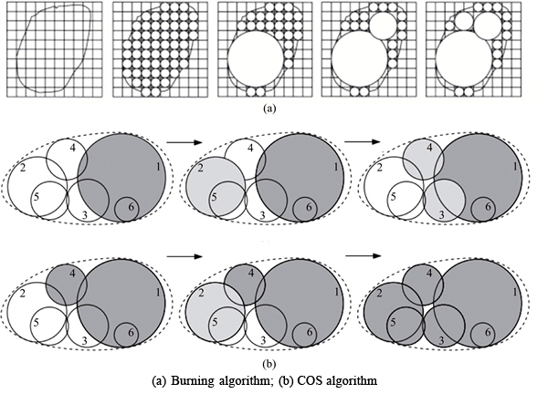
Fig. 4 Schematic operations of two analogous algorithms for particle representaion in Refs. [19] and [20]:
Based on a simple idea, ASHMAWY et al [21] proposed an overlapping method in 2D (called ODEC2D) to model the particles of angular shape. As shown in Fig. 5(a), some overlapping disks clumped together as a cluster to capture the shape are inscribed within the particle outline, and the number of the overlapping disks depends on the degree of non-uniformity in particle shape and angularity. As a result, the desired level of geometric accuracy is satisfied as well as the required computation time. However, the algorithm relied mainly on several manual operations which necessarily warranted the development of a computer-based technique. For automatic and efficient performance of ODEC2D, DAS [22] improved it by use of skeletonization of the shape, which is defined as the locus of centers of maximally inscribed disks. Figure 5(b) shows schematic operation of the improved algorithm to generate a cluster based on the skeleton of the particle outline, which includes the following processes: a biggest disk covering maximum area is inscribed within the particle outline firstly; then the next disk to be added is the one that covers the maximum uncovered area; and so on, the above operation is continued until the desired percentage of the particle area is covered. As shown in Fig. 5(b), a cluster generated for an irregular particle by the improved algorithm gives an accurate approximation to the particle shape.
Compared to the overlapping methods above, FERELLEC et al [23] proposed a relatively simple and fast method to generate a cluster for representation of an irregular particle. As shown in the Figs. 6(a) and (b), the algorithm consists of choosing randomly a point on the outline of real particle, growing internally a tangent disk along its normal direction to maximal extent possible inside the outline of the real particle and repeating the above steps for other points on the outline last. Without consideration of any constraint, the disks generated by the algorithm are usually equal to the number of points on the outline of the particle. In order to get a balance between computational cost later in DEM and the accuracy of the reproduced shape, three parameters had been introduced to reduce the number of disks in a cluster and the computational cost later in DEM (Fig. 6(c)). However, the algorithm cannot give a good result if the particles have a sharp shape.
2.3 Advantages and disadvantages
In the overlapping approaches, a cluster can give a relatively precise approximation to the particle shape with fewer disks as the disks in the cluster are allowed to overlap between them. However, overlaps between the disks in the cluster may result in inconsistent mass distribution of the cluster compared with that of the real particle, which may lead to the errors in mass properties between the cluster and the real particle [20]. This unreasonable situation is less likely to occur for non-overlapping approaches because the disks in a cluster are not allowed to overlap with each other. In addition, the cluster generated by the non-overlapping approaches can also be used to simulate the particle breakage [24, 25]. However, clusters generated by current non-overlapping methods only give a coarse representation of particle in terms of the shape and mass properties.
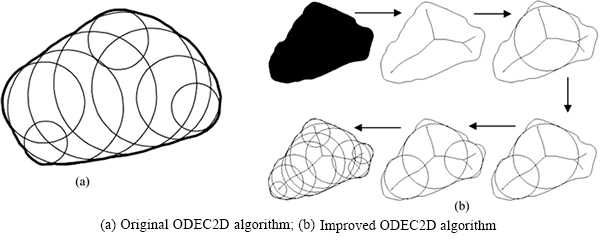
Fig. 5 Schematic operation of ODEC2D algorithm for particle representation in Refs. [21, 22]:
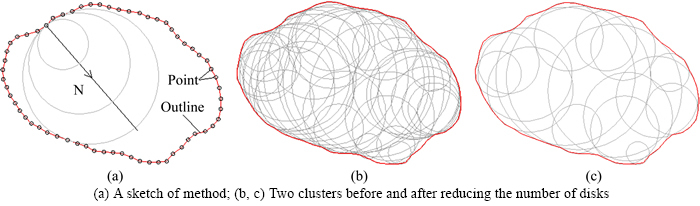
Fig. 6 Illustration of a clustering method for particle representation of an irregular particle in Ref. [23]:
3 Principles of new algorithm
The new algorithm is composed of two components such as boundary filling and domain filling. For convenience and clearness, a flow chart of the algorithm to generate a cluster of non-overlapping disks for representation of a star-like particle is drawn to illustrate each component, as shown in Fig. 7.
3.1 Representation of outlines of real particles
The algorithm requires that the outlines of real particles are represented by polygons. A polygon includes three basic elements: vertices, edges and corners. For clearness below, some terminologies and conventions are introduced first here. As shown in Fig. 7(l), the vertices of the polygon are arranged counterclockwise and the first one V1 is identical to the last one V11; the edges are constructed by connecting the vertices from the first one to the last one successively; the corners are formed by two adjacent edges at each vertices.
3.2 Boundary filling
In order to obtain a good description of the shape of a real particle, some disks are placed along interior side of its boundary, as shown in Fig. 7(c). The process of placement of the disks is called boundary filling, including two sub-steps: placement of the disks at the corners (Fig. 7(a)) and placement of the disks along the edges (Fig. 7(b)).
In the first sub-step of boundary filling, the centers of disks with the same radius  are placed on the interior angle bisector of each corner (Fig. 7(a)), so the number of the disks is equal to that of corners. There are two cases for the placement of a disk at a corner, depending on the degree of the interior angle of the corner. As shown in the Fig. 7(a), if the interior angle of a corner such as C4 or C6 is less than or equal to 180°, the center of a disk is placed at the position where the disk is inscribed with two edges of the corner. On the other hand, if the interior angle of a corner such as C3 or C7 is greater than 180°, the center of the disk is located at the point with a distance equal to the disk radius from the vertex located at the corner.
In the second sub-step of boundary filling, disks with the same radius  (except those placed last along each edge, for example, the blue one in Fig. 7(b)) are placed successively along the interior side of each edge. Taking placement of the disks along the edge E1 for example, the first disk is placed based on the condition of being tangent to the edge E1 and the placed disk located at the corner C1; the second one is placed based on the condition of being tangent to the edge E1 and the disk placed first; the next one is placed by the similar operation, As shown in Fig. 7(b). In this process, the central position of a disk with a radius of
  ((x, y)) can be determined by
 (1)
(1)
where (x1, y1) and r1 are the central position and radius of the disk placed last in this process (green one in Fig. 7(b)), and (nx, ny) is the normal unit vector of the first edge, (xp, yp) is a point located on the first edge. The process of placement of the disks along the edge E1 is finished until the placed disk (red one in Fig. 7(b)) overlaps with the disk located at the corner C2, and this placed disk will be replaced by a new disk (blue one in Fig. 7(b)). The central position and radius of the new disk can be obtained by solving the following equations:
 (2)
(2)
where (x, y) and r are the central position and radius of the new disk, respectively, and subscripts 1 and 2 denote the disk placed last and the disk located at the corner C2. In general, two candidates with different radii can be obtain by solving Eq. (2), while only the one with a smaller radius is accepted.
Similarly, placements of the disks along other edges are performed by the above operations, as shown in Fig. 7(c). In order to avoid some overlaps between the disks located near a corner (especially for a sharp one), a relation  is established in the boundary filling, which means that the radius of a disk placed along an edge is equal to half of that of a disk placed at a corner.
An optional operation, boundary refilling, is developed to improve the shape similarity if the resulting outline of all placed disks cannot give a precise approximation to the particle shape after boundary filling. It includes edge refiling and corner refilling, as shown in Fig. 7(d). In the edge refilling, some extra disks are placed based on the condition of being tangent to the edges and two neighboring disks, and their central positions and radii are obtained by solving Eq. (2). For a sharp corner such as C11, a disk placed at the corner may not capture the characteristic of the sharpness. Hence some extra disks are placed at the corner to improve the shape similarity, and this process is called corner refilling. A distance (d), which is measured from the center of the disk placed at the corner to the vertex located at the corner, is employed to determine the implement of corner refilling. Some new disks are placed at the corner in sequence if the distance satisfies
 (3)
(3)
where α is a factor greater than 1.0. In the corner refilling, the disks to be placed are tangent to each other and the two edges forming the corner (Fig. 7(d)). In general, countless disks will be placed at the corner without a restriction on their radii, so a constraint is used here, that is, the radius of the disk to be placed is greater than or equal to half of that of the disk placed at the corner. After the boundary filling, the existing disks are clumped together as a part of the cluster. It can be clearly seen from Fig. 7(d) that the outline of the cluster gives a precise approximation to the boundary.
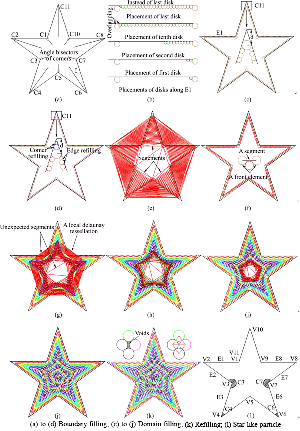
Fig. 7 Flow chart of our algorithm to represent a star-like particle by a cluster:
3.3 Domain filling
In order to make the mass properties of the cluster approximate to those of a real particle (the mass properties of a cluster will be presented in Section 4), some more disks are placed in the domain step by step based on a local Delaunay tessellation, as shown in Figs. 7(j) to (i). The process called domain filling is similar to that of seed expansion method (SEM) presented in the Ref. [16]. However, it is a difference between the method that new disks are placed inwards step by step by our algorithm, and the method that the disks are generated outwards by seed expansion method.
In the first step of domain filling, a set of points composed of the centers of the disks (except the disks generated in boundary refilling) located along the boundary are used to create a Delaunay mesh based on Delaunay triangulation first (Fig. 7(e)); then the segments are extracted from the Delaunay mesh, each of them connects two disks which are called a front element (Fig. 7(f)); afterwards rational front elements are selected based on the relation (4) because many unexpected segments extracted from a Delaunay mesh exist in the domain filling (Fig. 7(g)). A front element is called a rational one and selected to generate a new disk only if the length of the segment connecting the front element satisfies
 (4)
(4)
where ri and rj are the radii of the two disks of a front element, respectively; rd is the radius of a new disk to be placed; Lij is the length of the segment connecting the front element. The selected rational front elements are used to generate new disks in the domain last. Provided that the central positions of two disks of a rational front element are (x1, y1) and (x2, y2) with radii r1 and r2, respectively; the central position of a new disk with a radius of rd, denoted by (x, y), can be obtained by
 (5)
(5)
A new disk is valid if it satisfies two requirements: it doesn’t overlap with the existing disks and it must be completely contained within the domain. If the condition is satisfied, a new disk will be placed in the domain and incorporated into the cluster. Generally, two candidate disks are obtained by Eqs. (5), and both of their validities are checked.
After the first step of domain filling, the valid disks are placed in the domain and added into the cluster, as shown in Fig. 7(f). Similarly, the existing disks in the cluster (except the disks generated in boundary refilling) are selected for the next step of domain filling by repeating the above operations. More and more new disks are placed in the domain and added into the cluster with the continuous operation of domain filling (Figs. 7(j)-(i)). If the existing disks in the cluster are selected for the next step of domain filling, it will require more computational time to complete domain filling when the number of the disks become larger. A similar strategy presented in the Ref. [16] is adopted to save the computational time, where only a part of disks in the cluster are selected for the next step of domain filling. To do this, a sequence number which indicates the step sequence of domain filling is assigned to each disk. For example, the sequence of each disk placed in the first step of domain filling is specified as 1 and so on. As shown in Figs. 7(f)-(j), the disks have the same sequence and are marked by the same color if they are placed in the same step of domain filling. In addition, an advancing-front thickness (h) defined as the difference of two sequence number is adopted to select the disks for the next step of domain filling. Suppose ln represents the sequence number of a disk placed in the current step of domain filling, the disks are only selected for the next step of domain filling if their sequence number l satisfies
 (6)
(6)
If h is set to a larger enough number, all disks are selected for the next process of domain filling. And it will require more computational time for domain filling. On the other hand, if h is set to 1, only the disks placed in the last step of domain filling are selected for the next process of domain filling, and it will result in the algorithm is not convergent. A reasonable value of h is given before the domain filling, which will be discussed later.
3.4 Parameters of algorithm
As presented in Sections 3.2 and 3.3, a disk is placed in the boundary filling and domain filling based on different conditions, and its central position can be obtained by solving Eq. (1) or Eq. (5) when its radius is given by users in advance. In the following, determination of the disk radius and the parameters of the algorithm are introduced in the boundary filling and domain filling.
In the boundary filling, the radius of a disk  or
or  need to be given by users in advance. For the practicability of our algorithm, a parameter (Nb) denoting the number of the disks placed along the shortest edge is proposed to determine
  and
and  indirectly. For an arbitrary particle, the length of its shortest edge (Lmin) can be obtained automatically by the algorithm before boundary filling. and are determined based on the relation
  when Nb is given by users, and it is very easy for users to adjust the shape of a cluster by changing Nb.
In the domain filling, the radius of a disk (rd) need to be given by users in advance and ranges randomly and uniformly in an interval [rmin, rmax]. The radii of the disks placed in this process are identical if rmin is equal to rmax. Two parameters (fr and rmin/rmax) are introduced to determine the interval [rmin, rmax]. fr is defined as a ratio of rmin to  and rmin/rmin is defined as a ratio of rmax to rmin. Besides, an advancing-front thickness h also needs to be selected in the domain filling for convergence of the algorithm.
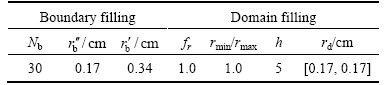
In general, our algorithm to generate a cluster for a real particle includes four input parameters such as Nb, fr, rmax/rmin and h. As shown in Fig. 7(j), a cluster is generated for the star-like particle by our algorithm based on the parameters listed in Table 1.
Table 1 Parameters of algorithm for generation of a cluster for a star-like particle
4 Determination and correction of mass properties of clusters
4.1 Determination of mass properties
For a continuous body in 2D, its mass properties include the total mass (m), position of the center of mass (x) and moment of inertia (I), which are significantly important for dynamic simulation. Here, an axis of rotation through the body’s center of mass and perpendicular to the body is defined to determine the moment of inertia because it is different around different axes of rotation. The mass properties of the body can be determined by
 (7)
(7)
 (8)
(8)
 (9)
(9)
For a cluster comprised of Nd non-overlapping disks as a rigid body, its mass properties (the total mass (m′), position of the center of mass  and moment of inertia (I′)) can be evaluated by Eqs. (11)-(13) if all disks in the cluster have an identical density (ρ).
 (10)
(10)
 (11)
(11)

 (12)
(12)
where m[d] is the mass of a disk in the cluster; x[d] and r[d] are respectively the centre position and radius of the disk.
4.2 Parameter effects on shape and mass properties of a cluster
To investigate the effects of the parameters of our algorithm on the shape and mass properties of a cluster, the star-like particle shown in Fig. 7(l) is used here. The mass properties of the star-like particle (m, xc and I) and those of the cluster generated by our algorithm (m′,  and I′) can be calculated by Eqs. (7)-(9) and Eqs. (10)-(12), respectively. Two indexes (m′/m, and I′/I) are introduced to quantify the errors between the cluster and the particle in terms of mass properties. m′/m and I′/I are defined as ratios of total mass and moment of inertia of the cluster to those of the particle, respectively.
As shown in Fig. 7(j), the shape of a cluster is determined by the resulting outline of the disks placed in the boundary filling, and only small part of the domain of the star-like particle is occupied by the disks placed in the boundary filling. So, boundary filling exert a main influence on the shape of a cluster compared with the mass properties of a cluster. For boundary filling, the parameter Nb determines the number and radii of the disks in a cluster. The larger number Nb is input by users, the more disks are placed along the boundary, and the resulting outline of the disks gives a better representation to that of a real particle. In practice, it is often sufficient to place several disks along its shortest edge for a real particle.
As shown in Fig. 7(j), most of the domain of the star-like particle is occupied by the disks placed in the domain filling, so the parameters of domain filling has great effects on the mass properties of a cluster. It is founded from Figs. 8(a) and (b) that m′/m and I′/I basically keep unchanged when h is greater than 3, while they both have a large increase when h changes from 2 to 3. The main reason is that the convergence of the algorithm cannot be achieved when h is equal to 2, as shown in Fig. 8(d). On the other hand, it is also seen clearly from Fig. 8(d) that the center of mass is always close to that of the particle with h greater than 3. Besides, more computational time is consumed in the domain filling with h increasing. So, it is suggested that h varies 5 to 7 for an arbitrary particle based on our experience.
It is seen clearly from Figs. 9(a) and (b) that m′/m and I′/I reduces gradually with fr increasing from 0.4 to 1.6 when h is equal to 5. In other words, the total mass and moment of inertia of the cluster get closer to those of a real particle when the disk radius increases. On the other hand, a slight change is brought about in the total mass and moment of inertia when rmax/rmin varies from 1.0 to 2.0 with fr unchanged. It is found from Fig. 9(c) that center of mass is always close to that of the particle with fr and rmax/rmin changing. So, it indicates that the disk radius have a slight impact on center of mass.
In conclusion, fr and rmax/rmin have a great influence on total mass and moment of inertia, while h determines the efficiency and convergence of the algorithm. The parameters of domain filling make a slight influence on center of mass with the convergence of the algorithm.
4.3 Correction of mass properties
As shown in Fig. 7(k), some voids still exist between the disks after domain filling, which leads to the errors of the mass properties between the cluster and the particle. It is also seen from Figs. 8(a) and (b) and Figs. 9(a) and (b) that the errors of approximately 20% to 30% exist in the total mass and moment of inertia after domain filling. Refilling proposed by LIU et al [16] for improvement of the packing density can be adopted to reduce the errors. In the refilling, some smaller disks are placed in the voids, as shown in Fig. 7(k). However, the process of refiling is time-consuming and the number of the disks increases sharply. Considering the computational load later in DEM, it is unrealistic to improve the mass properties of a cluster by repeating refilling.
It is seen clearly from Eqs. (10)-(12) that the total mass and moment of inertia of a cluster are related to the density of ρ while the center of mass is independent of it.
Based on the conclusion, a simple method is proposed to correct the total mass and moment of inertia by adjusting the disk density, and the new disk density (ρ′) is determined by
 (13)
(13)
 (14)
(14)
 (15)
(15)
By this correction, the total mass and moment of inertia of a cluster get closer to those of the particle without increasing of the number of disks, meanwhile its center of mass keep unchanged.
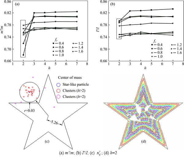
Fig. 8 Effects of fr and h on mass properties of a cluster (rmax/rmin=1.2):
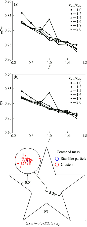
Fig. 9 Effects of fr and rmin/rmax on mass properties of a cluster (h=5):
4.4 Reduction of number of disks in a cluster
For lower computational cost later in DEM, as few disks as possible should be placed in the domain filling. Although the mass properties of a cluster are affected by the disks placed in the domain filling, they may be corrected by the proposed method. The number of the disks placed in the domain filling is determined by three parameters (fr, rmax/rmin and h). Among them, fr has a relatively great influence on the number of the disks. Hence the purpose of reducing the number of the disks in a cluster is achieved easily by increasing fr in the domain filling. Figure 10 shows three clusters generated by our algorithm based on different fr and Nb=30, rmax/rmin and h=5. As shown in Table 2, the number of the disks placed in the domain filling reduces largely from 1029 to 107 with an increase of fr from 1.0 to 3.0, while the errors of total mass and moment of inertia increase slightly. It is founded form Table 2 that although the number of the disks in the Cluster-3 reduces significantly, its mass properties are still close to those of the particle after correction.
5 Application
5.1 Replacements of non-circular primitives
As mentioned in Section 1, some non-circular primitives have been used for an approximate representation of particulate materials in order to obtain more accurate simulation result. Without introduction of a new primitive into DEM, the same goal can also be reached by replacement of a non-circular primitive by a cluster, meanwhile the cluster is capable of considering the particle breakage in the simulation of DEM. For example, replacement of an ellipse-shaped primitive includes the following processes: the primitive is approximated by a polygon of similar shape first, as shown in Fig. 11(a), then a cluster is generated after boundary filling and domain filling to represent the primitive, as shown in Figs. 11(b) and (c). The parameters of the algorithm is listed in Table 3, and the mass properties before and after correction are listed in Table 4. As shown in Table 4, the cluster gives a prefect representation of the ellipse-shaped primitive after correction of the mass properties.
5.2 Generation of clusters for an assembly of particles
Two assemblies of irregular particles with different shapes and sizes (Model 1 and Model 2) are used to show validity and robustness of our algorithm. As shown in Fig. 12(a), Model1 is a Voronoi tessellation composed of 41 polygonal particles. As shown in Fig. 12(e), Model 2 is a random mesoscopic structure of outwash deposits (RMS) generated based on the proposed method in the Ref. [26]. It includes 121 polygonal particles and the shape, size and distribution of polygons resemble stones in the statistical sense. The clusters can be generated fast for Model 1 and Model 2 by our algorithm. Figures 12(b)-(d) and (f)-(h) show the processes of generation of clusters for Model 2 and Model 2, respectively.
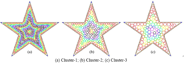
Fig. 10 Three clusters generated by algorithm based on different fr:
Table 2 A comprehensive comparisons between three clusters generated based on different fr
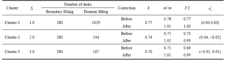
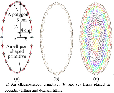
Fig. 11 Replacement of an ellipse-shaped primitive by a cluster:
Table 3 Parameters of algorithm for representation of an ellipse-shaped primitive
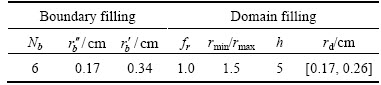
Table 4 Mass properties of cluster before and after correction

5.3 Generation of a packing for DEM
Another application of our algorithm is generation of a packing for DEM in which the radius of a disk is selected according to the size distribution specified by users in the boundary filling and domain filling. To verify the performance of our algorithm in generating a packing according to the specified density and size distribution. A rectangle with dimensions 10 cm×15 cm is filled by disks with the packing density of 0.75 and the size distribution is shown in Fig. 13(b). The advancing- front thickness h is 6, and refilling isn’t performed. The packing generated by our algorithm is shown in Fig. 13(a), and the number of the disks in the packing is 3594. As shown in Fig. 13(b), the size distribution generated by the algorithm is in accordance with that specified by users, and the density of the generated packing is equal to the specified value of 0.75.
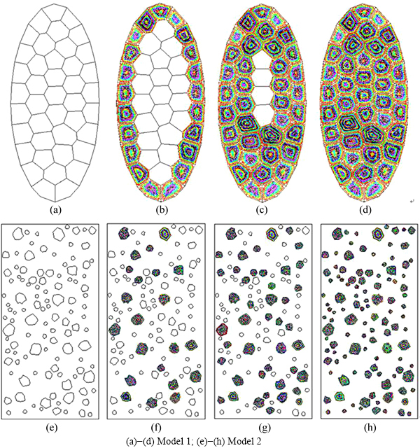
Fig. 12 Processes of generation of clusters for two assemblies (Model 1 and Model 2):
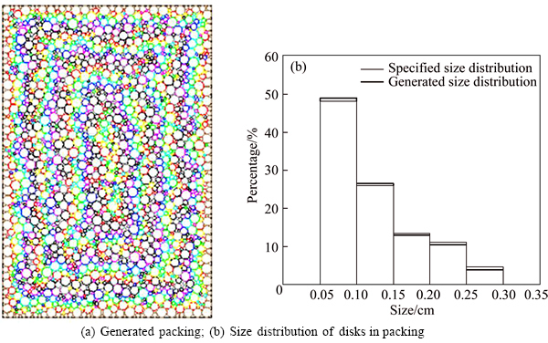
Fig. 13 A packing generated by algorithm according to specified size distribution:
6 Conclusions
1) A robust and efficient algorithm is developed to accurately represent an arbitrary particle for DEM modelling by a cluster of non-overlapping disks. A cluster generated by the algorithm can give a good representation of the particle shape and the mass properties. Another application of the algorithm is generation of a packing according to the specified size distribution for DEM.
2) Without introduction of an ellipse-shaped primitive into DEM, an ellipse-shaped particle can be modeled by a cluster of non-overlapping disks based on our algorithm, and its breakage is also considered in the simulation.
3) A current FORTRAN version of the algorithm is available upon request for academic use, and it includes four parameters whose suggested values are given in the paper for the practicability and superiority of the algorithm. So it is very convenient and easy for users to generate a cluster for an irregular particle in the DEM modelling.
References
[1] CUNDALL P A, STRACK O D L. A discrete numerical model for granular assemblies [J]. Geotechnique, 1979, 29(1): 47-65.
[2] Donze F V, Richefeu V, Magnier S A. Advances in discrete element method applied to soil, rock and concrete mechanics [J]. Electronic Journal of Geotechnical Engineering, 2009, 31: 1-44.
[3] Cho G C, Dodds J, Santamarina J C. Particle shape effects on packing density, stiffness, and strength: Natural and crushed sands [J]. Journal of Geotechnical and Geoenvironmental Engineering, 2006, 132(5): 591-602.
[4] Nouguier-Lehon C, Cambou B, Vincens E. Influence of particle shape and angularity on the behaviour of granular materials: A numerical analysis [J]. International Journal for Numerical and Analytical Methods in Geomechanics, 2003, 27(14): 1207-1226.
[5] Lane J E, Metzger P T, Wilkinson R A. A review of discrete element method (DEM) particle shapes and size distributions for lunar soil [M]. Cleveland, USA: Glenn Research Center, National Aeronautics and Space Administration, 2010.
[6] Ting J M, Khwaja M, Meachum L R, Rowel J D. An ellipse- based discrete element model for granular materials [J]. International Journal for Numerical and Analytical Methods in Geomechanics, 1993, 17(9): 603-623.
[7] Mirghasemi A A, Rothenburg L, Matyas E L. Influence of particle shape on engineering properties of assemblies of two- dimensional polygon-shaped particles [J]. Geotechnique, 2002, 52(3): 209-217.
[8] Lu G, Third J R, MUller C R. Critical assessment of two approaches for evaluating contacts between super-quadric shaped particles in DEM simulations [J]. Chemical Engineering Science, 2012, 78: 226-235.
[9] HOGUE C. Shape representation and contact detection for discrete element simulations of arbitrary geometries [J]. Engineering Computations, 1998, 15(3): 374-390.
[10] LI Cheng-qing, XU Wen-jie, MENG Qing-shan. Multi-sphere approximation of real particles for DEM simulation based on a modified greedy heuristic algorithm [J]. Powder Technology, 2015, 286: 478-487.
[11] WANG Sheng-nian, XU Wei-ya, SHI Chong, ZHANG Qiang. Numerical simulation of direct shear tests on mechanical properties of talus deposits based on self-adaptive PCNN digital image processing [J]. Journal of Central South University, 2014, 21: 2904-2914.
[12] Kruggel-Emden H, Rickelt S, Wirtz S, Scherer V. A study on the validity of the multi-sphere discrete element method [J]. Powder Technology, 2008, 188(2): 153-165.
[13] Jensen R P, Bosscher P J, Plesha M E, Edil T B. DEM simulation of granular media-structure interface: effects of surface roughness and particle shape [J]. International Journal for Numerical and Analytical Methods in Geomechanics, 1999, 23(6): 531-547.
[14] Itasca Consulting Group Inc. PFC2D (Particle flow code in 2 dimensions) (Version 3.1) [R]. Minneapolis: Itasca Consulting Group Inc., 2004: 818-834.
[15] Itasca Consulting Group Inc. PFC3D (Particle flow code in 3 dimensions) (Version 3.1) [R]. Minneapolis: Itasca Consulting Group Inc., 2005: 482-498.
[16] LIU Jun, YUN Bin, ZHAO Chang-bing. An improved specimen generation method for DEM based on local Delaunay tessellation and distance function [J]. International Journal for Numerical and Analytical Methods in Geomechanics, 2012, 36(5): 653-674.
[17] Thakur P K, Vinod J S, Indraratna B. Effect of particle breakage on cyclic densification of ballast: a DEM approach [C]// IOP Conference Series: Materials Science and Engineering. IOP Publishing, 2010, 10(1): 012229
[18] WANG Sheng-nian, SHI Chong, XU Wei-ya, WANG Huan-lin, ZHU Qi-zhi. Numerical direct shear tests for outwash deposits with random structure and composition [J]. Granular Matter, 2014, 16(5): 771-783.
[19] WANG Lin-bing, PARK J Y, FU Yan-rong. Representation of real particles for DEM simulation using X-ray tomography [J]. Construction and Building Materials, 2007, 21(2): 338-346.
[20] GARCIA X, LATHAM J P, XIANG Jin-sheng, HARRISON J P. A clustered overlapping sphere algorithm to represent real particles in discrete element modeling [J]. Geotechnique, 2009, 59(9): 779-784.
[21] Ashmawy A K, Hoang V V, Sukumaran B. Evaluating the influence of particle shape on liquefaction behavior using discrete element modeling [C]// The Thirteenth International Offshore and Polar Engineering Conference. International Society of Offshore and Polar Engineers. 2003: 542-549.
[22] DAS N. Modeling three-dimensional shape of sand grains using discrete element method [D]. Tampa, US: University of South Florida, 2007.
[23] Ferellec J F, McDowell G R. A method to model realistic particle shape and inertia in DEM [J]. Granular Matter, 2010, 12(5): 459-467.
[24] Hossain Z, Indraratna B, Darve F, Thakur P K. DEM analysis of angular ballast breakage under cyclic loading [J]. Geomechanics and Geoengineering, 2007, 2(3): 175-181.
[25] Indraratna B, Ngo N T, Rujikiatkamjorn C, Vinod J S. Behavior of fresh and fouled railway ballast subjected to direct shear testing: Discrete element simulation [J]. International Journal of Geomechanics, 2014, 14(1): 34-44.
[26] ZHU Hua-xiang. Mechnical parameter study of deposit body based on randomized block modeling [D]. Nanjing: Hohai University, 2012. (in Chinese)
(Edited by DENG Lü-xiang)
Cite this article as: ZHANG Qiang, XU Wei-ya, LIU Qin-ya, WANG Wei, MENG Qing-xiang. A novel non-overlapping approach to accurately represent 2D arbitrary particles for DEM modelling [J]. Journal of Central South University, 2017, 24(1): 190-202. DOI: 10.1007/s11771-017-3420-1.
Foundation item: Project(2011CB013504) supported by the National Basic Research Program (973 Program) of China; Project(2013BAB06B01) supported by Key Projects in the National Science & Technology Pillar Program during the Twelfth Five-year Plan Period, China; Projects(51309089, 51479049) supported by National Natural Science Foundation of China; Project(487237) supported by Natural Sciences and Engineering Research Council of Canada
Received date: 2015-06-23; Accepted date: 2016-01-18
Corresponding author: MENG Qing-xiang, PhD; Tel: +86-15951089972; E-mail: mqx4088@gmail.com

