������Һ�е�������Ʊ�����ͭ��֯�ͽᾧ����
��Դ�ڿ����й���ɫ����ѧ��(Ӣ�İ�)2017���6��
�������ߣ�R. SEAKR
����ҳ�룺1423 - 1430
�ؼ��ʣ������Σ�ͭ����������Ӽ�
Key words��acetate; copper electrodeposition; additives
ժ Ҫ���ڴ�ͳ�������ͭ�м��������һ�ֿ�ѡ��ĵ��Һ���ӻ����Ѻõ���������Һ�е����ͭ���õ��Һ������ͭ�������ơ����������ɡ�����ά���ء��Ǿ���4-����-3-�ǻ�-1-������Ϊ�������Һ�����Ӽ������÷����ڶ��ɼ�����������Ч�ʣ���ʹ��Haring-Blum���ȷ����Һ�еĽ����ֲ��ȡ���Щ���Ӽ�Ӱ���˳���ͭ��Ĥ�ı�����ò������SEM��XRD�ֶη����侧���ߴ硣XRD�ױ��������ͭ�Ƕྦྷ����������ṹ������Debye-Scherrer��ʽ���㱡Ĥ�ľ�����С������ߴ���������Һ���Ӽ������õ��IJ��������С�ľ����ߴ硣֯��ϵ���������������е�ͭ����Ĥ���Ƕྦྷ�ṹ����������ȡ��ƽ���ڱ��档���Ӽ������˾��ȵ�����ױ�����ò�;���ϸ����
Abstract: Methane sulphonic acid is an alternative electrolyte for conventional sulphuric acid for copper deposition. The electrodeposition of copper from eco-friendly acetate-based electrolytes consisting of copper acetate, sodium acetate and methane sulphonic acid was dealt. Thamine hydrochloride (THC), saccharin and 4-amino-3-hydroxynaphthalene 1-suphonic acid were used as additives in depositing electrolytes. The cathode current efficiency was calculated using the Faraday��s law. Metal distrbution ratio of the solutions was determined using Haring-Blum cell. These additives impact the surface morphology of deposited copper films by downgrading, the grain size was analyzed by scanning electron microscopy (SEM) and X-ray diffiraction technique. XRD pattern acquired for electrodeposited copper film shows polycrystalline and face centered cubic structure (FCC). The crystal size of the copper film was calculated using the Debye-Scherrer��s equation. The crystal size revealed that deposits produced from additive containing electrolytes exhibited the lowest grain size. Texture coefficient analysis studies revealed that all copper film deposits are polycrystalline and the crystals are preferentially oriented and parallel to the surface. A uniform and pin-hole free surface morphology and grain refining were brought about by the additives.
Trans. Nonferrous Met. Soc. China 27(2017) 1423-1430
R. SEAKR
Electroplating and Metal Finishing Technology Division, Central Electrochemical Research Institute, Karaikudi-630 006, Tamil Nadu, India
Received 28 April 2016; accepted 23 September 2016
Abstract: Methane sulphonic acid is an alternative electrolyte for conventional sulphuric acid for copper deposition. The electrodeposition of copper from eco-friendly acetate-based electrolytes consisting of copper acetate, sodium acetate and methane sulphonic acid was dealt. Thamine hydrochloride (THC), saccharin and 4-amino-3-hydroxynaphthalene 1-suphonic acid were used as additives in depositing electrolytes. The cathode current efficiency was calculated using the Faraday��s law. Metal distrbution ratio of the solutions was determined using Haring-Blum cell. These additives impact the surface morphology of deposited copper films by downgrading, the grain size was analyzed by scanning electron microscopy (SEM) and X-ray diffiraction technique. XRD pattern acquired for electrodeposited copper film shows polycrystalline and face centered cubic structure (FCC). The crystal size of the copper film was calculated using the Debye-Scherrer��s equation. The crystal size revealed that deposits produced from additive containing electrolytes exhibited the lowest grain size. Texture coefficient analysis studies revealed that all copper film deposits are polycrystalline and the crystals are preferentially oriented and parallel to the surface. A uniform and pin-hole free surface morphology and grain refining were brought about by the additives.
Key words: acetate; copper electrodeposition; additives
1 Introduction
Copper is one of the most significant non-ferrous materials, because it is widely used in electrical and electronic industries for production of tubes, wires, sheets and for making copper-based alloys. Although, copper deposits have an excellent conductivity because free and mobile electrons are more in copper lattice. Alkaline cyanide electrolytes are still used to electroplate copper and have various applications for the metal finishing industry [1]. In recent years a plenty of research has been realized and various alternatives have been proposed, such as chloride, amine-ammonia, sorbitol, fluoborate, pyrophosphate, EDTA, citrate, tatarate, ethylenediamine (EDA), triethanolamine (TEA) and glycine to replace the cyanide electrolytes for its environmental concerns, because of environmental, economic or some other limitations [2]. However, most of these proposals have not been taken to industrial level. QUINET et al [3] have studied the influence of saccharin and thiourea, on electrodeposition of copper from acid sulphate solutions using various electrochemical methods. TOROK et al [4] have investigated the direct cathodic deposition of copper on steel wires from pyrophosphate solutions. Electroplating of copper from methane sulphonic acid electrolytes for interconnects in ultralarge scale (ULSI) and microelectrochemical systems (MEMS) applications [5]. CAO et al [6] have investigated the effect of chloride ion in the methanesulphonic acid electrolytes by using electron paramagnetic resonance (EPR) and various electrochemical techniques. Copper film is produced on AZ31 magnesium alloy by electrodeposition using copper hydroxide and citrate solution with the addition of sodium fluoride, SP, MZ and PEG [7]. Systematic studies on copper deposition on stainless steel from a sulphate electrolyte had been undertaken using square wave pulse current and direct current [8]. MANTRY et al [9] have studied the deposition potential of copper slag for different engineering and structural applications by plasma spray technique. The influences of gelatin on cuprous copper electrodeposition in ammonical alkaline solutions were investigated [10]. In electroplating bath formulations, the presence of organic and inorganic compounds introduced in trace amounts, called additives, exerts significant effects on metal deposition. In fact, additives modify the crystal growth and improve the physical and mechanical properties of the electrodeposits. Some additives may inhibit or catalyze the electrodeposition process by forming complexes with metallic ions or increasing the polarization of metal electrodeposition due to their adsorption on active sites [11]. LOW and WALSH [12] have studied the normal and anomalous codeposition of copper-tin alloy from methanesulphonic acid solution in the presence of perfluorinated cationic surfactant. SEKAR et al [13] have investigated the results on copper depositing electrolytes characteristics such as electrolyte stability, galvanic displacement reaction of copper on mild steel, deposition current efficiency, metal distribution of the depositing electrolytes and deposit characteristics like adhesion, quality of the copper deposit, crystal size, orientation of the crystal and microstructure using scanning electron microscopy (SEM) and X-ray diffraction analysis (XRD). The effects of plating parameters such as characteristics of depositing solutions, quality of the deposits and throwing power of the depositing electrolytes were investigated [14]. IBRAHIM et al [15] have investigated the electrodeposition of copper from aqueous ammonia solutions onto steel substrates and its deposit characteristics were studied by various electrochemical techniques [15]. SIVASAKTHI et al [16] have investigated the detailed study of electrodeposition of copper from glycerol complex and the influence of additives in alkaline medium. Moreover, electro- depositions of copper from acetate-based electrolytes have not been studied in detail. Hence, the authors desired to investigate the detailed study of electrodeposition of copper from acetate electrolytes using methane sulphonic acid (MSA) complex bath. In this paper, results on cathode current efficiency (CCE), throwing power of the depositing electrolytes (TP) and deposit characteristics such as adhesion, crystal structure and surface morphology are reported.
2 Experimental
2.1 Electrodeposition of copper and cathode current efficiency measurements
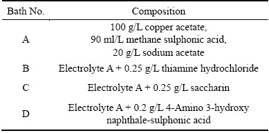
The alpha brass metallic foil consists of 75% copper and 25% zinc, which was used for the present study. Surface preparation prior to electrodeposition is an essential process and can be achieved by standard mechanical and electrochemical methods [17,18]. The pretreated brass foils with dimensions of 7.5 cm�� 2.5 cm��0.1 cm (7.5 cm length, 2.5 cm width, and 0.1 cm thickness) were used as cathodes in an electroplating cell consisting of two 99.99% pure copper as anodes on either side of the cathode. The depositing electrolyte consists of copper acetate ((CH3COO)2Cu��H2O), methane sulphonic acid (CH4O3S), and sodium acetate (CH3COONa) in the presence of various additives and the detailed electrolyte composition is given in Table 1. Doubly distilled water and analytical grade chemicals were used for the electrolyte preparation for the deposition of copper. The electrolyte was agitated mechanically throughout the experiment to progress the quality of the deposits. The plating bath was operated at room temperature and at different current densities. The cathodes were weighed before and after deposition; the deposition current efficiency and rate of deposition were calculated from the mass ratio of the copper deposits to the theoretically expected mass of copper deposits, which is based on the amount of current, according to the Faraday��s laws of electrolysis.
 (1)
(1)
where m is the mass of the deposits, Q is the electric charge passed, F is the Faraday constant (96485.3329 C/mol), M is the molar mass of the species and n is the electrical charge involved in the reaction.
Table 1 Formulation of various copper baths
2.2 Metal distribution of depositing solutions
The throwing power of the depositing electrolytes was determined using the Haring-Blum cell [19,20]. This is a rectangular cell consisting of two brass sheet cathodes with sizes of 5 cm �� 5 cm �� 0.1 cm filling the entire cross section at both ends of the cell walls, and one perforated copper anode of the same size. The latter was placed between the cathodes so that the distance from one of the cathode was one-fifth of its distance from the other. Values of throwing power (p) for different bath compositions were calculated using the Field��s formula.
 (2)
(2)
where R is the metal distribution ratio of the near to far cathode and L is the ratio of the respective distances of the far to near cathodes from the anode.
2.3 Adhesion and crystal structure of copper films
The bend test [21] was followed to evaluate the adhesion of the copper coatings on brass metallic foil. X-ray diffraction patterns were obtained for copper deposits using the X-pert pro powder diffraction system PE 3040/60 by scanning the samples at 30��-80��(2��) at a scan rate of 1 (��)/min using Cu K�� (��=1.5405  ) radiation. The peaks due to the different phases were identified and the corresponding lattice parameters were determined. The crystal size of the deposits was calculated using the Debye-Scherrer��s formula [22,23].
 (3)
(3)
where T is the average size of the crystal, 0.9 is the Scherrer constant, �� is the wavelength of radiation in nanometer (nm), �� is the peak width of the diffraction peak profile at half maximum height resulting from small crystallite size in radian and �� corresponds to the peak position (The �� can be in degree or radian, since the cos �� corresponds to the same number).
2.4 Texture coefficient of copper deposits
The particular plane and information were concerned by the preferential crystallite orientation determined from the texture coefficient as follows [24]:
 (4)
(4)
where �� is the texture coefficient of the specific (hkl) plane; I(hkl) is the measured intensity; I0(hkl) is the relative intensity of the standard JCPDS database number (65-2873), �� is the sum of the relative intensities of the independent peaks and N is the number of XRD peaks considered. The �� value is unity when the crystal orientation is random and no preferred orientation exists. The �� values exceed unity when the film has a preferred orientation and most of its grains are orientated in the same direction with their (hkl) planes parallel to the film surface.
2.5 Scanning electron microscopy analysis
The copper deposits obtained from different electrolytes were examined by scanning electron microscope (SEM) JEOL-JSM-35 LF Model (Japan) at 25 kV.
3 Results and discussion
3.1 Current efficiency and throwing power of depositing electrolytes
Depositing electrolyte composition and operating parameters were optimized by preliminary experiments. The operating pH was 2.1 at 30 ��C. The results of the cathode current efficiency (CCE) measurements performed at various current densities are shown in Fig. 1. Figure 1 (curve (a)) represents the electrolyte without any additives, the cathode current efficiencies steadily increase upto 3 A/dm2 and fall with increasing current densities and the quality of the copper deposit was affected. Hence, it suggests that high current density gives rise to depletion of Cu 2+ ion on the cathode surface, which results in dendrite growth. Moreover, the simultaneous hydrogen evolution reaction predominant consequently rate of deposition decreases and the deposits are loosely bonded to the substrate. It was concluded that 1-3 A/dm2 was optimum for producing a smooth uniform red color deposit with high current efficiency. The curve (b) shows the results of the CCE yielded from electrolyte B containing 0.25 g/L thiamine hydrochloride as additive. From this curve we may see that CCE steeply increases with increasing current density. It suggested that 2-4 A/dm2 was optimum for producing a smooth uniform bright copper deposit with high current efficiency and then the deposit becomes dull. Meanwhile, below 1 A/dm2 the deposits become darker red colour indentified. On the other hand, when organic additives are introduced to the depositing electrolyte, those ions are replaced by these additives which are adsorbed specifically or through the lone pair electron of sulfur and nitrogen atoms [25]. The study results from electrolyte C (curve (c)) containing 0.25 g/L saccharin as additive exhibited that CCE still increased to 100% at 4 A/dm2 and thereafter slightly dropped. It was identified that smooth uniform semi bright deposit was noticed between 2-4 A/dm2 but below 2 A/dm2. In fact, saccharin acts as not only primary brightener but also hydrogen suppressor. Hence, saccharin inhibits hydrogen evolution and increases the CCE of the depositing electrolyte. The study result from electrolyte D (curve (d)) containing 0.25 g/L 4-amino 3-hydroxy napthale-1-sulphonic acid as additive exhibited that CCE gradually increased still 2 A/dm2 and thereafter dropped with increasing current density. Hence, it was concluded that 1-2 A/dm2 is optimum for producing smooth uniform bright copper deposits. Moreover, additives are adsorbed on the electrode surface and thereby blocking the electrode surface, since cathode current efficiencies decrease with the induction of additives in the depositing electrolytes.
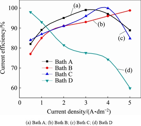
Fig.1 Effect of current density on current efficiency with varying current densities at 30 ��C in different copper electrolytes
3.2 Metal distribution of depositing electrolytes
The throwing power plays a significant role in all electroplating solutions. A solution with a high throwing power is capable of depositing almost equal thickness on both recessed and prominent areas. Figure 2 illustrates the variation of throwing power of baths A, B, C and D with different current densities. Figure 2 (curve (a)) indicates the copper plating electrolyte without additives (Bath A). It clearly indicates that throwing power increases with increasing current densities, leveling off at the higher values. This may be the reason for the increase in cathodic polarization with increasing current density. Curve (b) in Fig. 2 shows the copper plating electrolyte containing 0.25 g/L thiamine hydrochloride (Bath B), which exhibits that throwing power of the plating electrolyte significantly increases with increasing current density. Hence, it suggests that thiamine hydrochloride increases the conductivity of depositing electrolyte. Generally, a depositing electrolyte having high conductivity is associated with low energy consumption and greater throwing power [20]. When saccharin was added as additive, in Bath C throwing power increases with increasing current density, but as compared to Baths A and B, throwing power of the plating Bath C is lower. Generally, electrolytes free metallic ions exhibit poorer throwing power than those in which the ions are complexed; remarkably decreased cathode polarization at higher current densities results in increased CCE, decreasing throwing power. Similar behaviour was observed in Bath D containing 4-amino 3-hysroxy naphthale-sulphonic acid as additive.
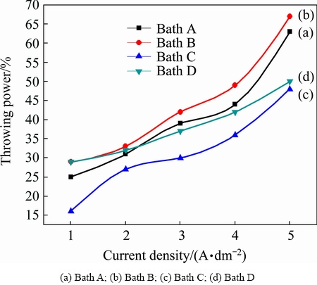
Fig. 2 Effect of current density on throwing power in different copper electrolytes at 30 ��C
3.3 Adhesion of copper deposits
Adhesion of the copper coatings was tested by subjecting the deposited mild steel metallic foils to standard bend tests as per ASTM Test method B 571-584 [21]. The copper coatings were found to withstand the bend test, exhibiting that the keying and adhesion of the coating to the metallic foil were very good in all cases.
3.4 Crystal structure of copper deposits
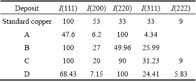
X-ray diffraction patterns of copper deposits obtained from different copper Baths A-D at 2 A/dm2 are shown in Fig. 3. The crystal size of the copper deposits yielded from the different copper plating electrolytes was calculated using the Debye-Scherrer formula and the values are recorded in Table 2. The deposits produced from all electrolytes are polycrystalline and face centered cubic crystal lattice. Figure 3(a) indicates the copper deposits produced from Bath A without additives at 2 A/dm2. The observed d values are in good agreement with the standard d values of copper [26]. The different faces of copper crystals obtained from various copper plating solution at 2 A/dm2 are recorded in Table 3. It clearly indicates that the reflection of (220) plane was more predominant as compared to the other peak intensities. In fact, the texture of the electrodeposits is mainly induced by different growth rates of differently oriented grain planes at given overpotential because of different atoms arrangement with different crystal faces. The growth rate sequence of different grain planes may change with the variation of the overpotential, resulting in the changes in the deposit texture. Therefore, grains with a (220) plane grow faster than other grains at the same overpotential. Figure 3(b) shows the X-ray diffractogram patterns of copper deposits produced from Bath B containing thiamine hydrochloride as additive at 2 A/dm2. From this figure, we may see that crystallographic orientation was changed in the presence of thiamine hydrochloride: the intensities of (111) and (220) peaks become the two main preferential orientations. Hence, it should be noted that the texture of electrodeposited copper is significant for device application. Moreover, a benefit demand for (111) texture component is that it is recognized to increase electrical conductivity at the copper electrodeposited layers. The X-ray diffraction patterns of copper deposit prepared from Bath C containing saccharin at 2 A/dm2 is shown in Fig. 3(c). (111) and (220) plane intensities were more predominant and the intensity of the peak corresponding to the (200) orientation decreased. The X-ray diffraction patterns of copper deposit prepared from Bath D containing 4-amino 3-hydroxy naphthale-sulphonic acid at 2 A/dm2 is shown in Fig. 3(d). The only (220) plane reflection was more predominant and the other peak intensities completely vanished. (111) and (220) peak intensities were more predominant and the intensity of the peak corresponding to the (200) orientation decreased. This may be the reason for the structural changes, reduced grain size and grain boundaries provoked by the synergistic effect of additives.
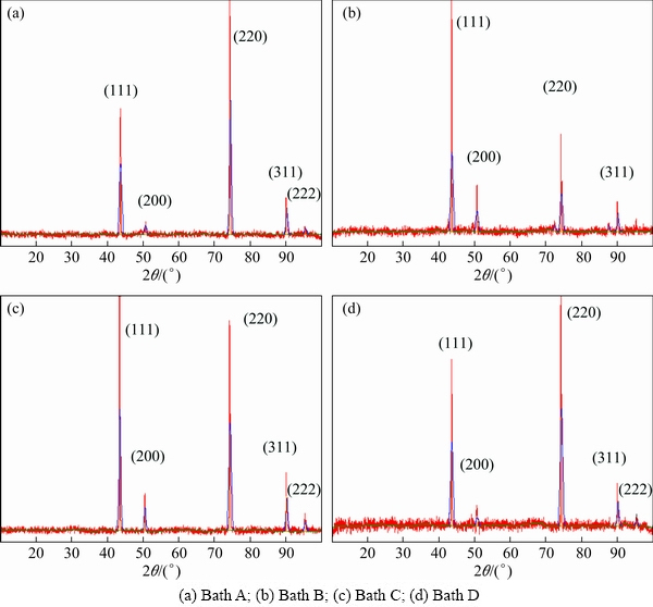
Fig. 3 XRD patterns obtained from copper films at 2 A/dm2
Table 2 Crystal size and texture coefficient obtained from different copper deposits
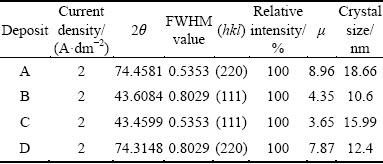
Table 3 Difference in intensity of crystal face between copper deposits with and without additives and face-centered cubic copper
3.5 Texture coefficient analysis of copper deposits
To determine the preferential orientation of the crystallographic plane of the copper deposits obtained from different electrolytes at 2 A/dm2, the texture coefficient for each orientation was calculated using Eq. (4) and the values are listed in Table 4. The index zero indicates the relative intensities for the standard power sample. The I(hkl)/I0(hkl) ratio indicates the normalized relative intensities of the reflection of a plane (hkl) of the deposit with respect to the same crystallographic orientation of copper powder. According to Eq. (4), the expression (1/N)��[I(hkl)/I0(hkl)] is the average of the normalized relative intensities of the reflections considered. When the texture coefficients of all reflection planes are unity, the distribution of crystal orientation is random. When the �� of any (hkl) plane is larger than unity, a preferred orientation or texture exists, in which grains are oriented with (hkl) planes parallel to the surface. The larger the value of ��, the greater the degree of the preferred orientation. From Table 4 we noted that, the copper film exhibited (220) plane, parallel to the surface and is dominant in the massive deposit produced without additives. Hence, it clearly denotes the preferred crystallographic orientation by a �� value larger than unity. When the addition of thiamine hydrochloride (THC) was added in bath B, the (111) plane preferred orientation was observed. Moreover, the crystalline size of the copper deposit was significantly reduced. This indicates that additives favour the surface parallel growth. Even though, the morphology of the copper deposit was varied from additive-free of Bath A. Hence, these results indicate that, in general, the macromolecules inhibit parallel growth of the new phase to some extent. With the introduction of saccharin in Bath C, two planes such as (111) and (220) preferential orientation were identified. On the other hand, the crystalline size of the copper deposit was not significantly reduced and the deposit becomes smooth and bright. Hence, saccharin acts as brightener but not a grain refiner. With the presence of 4-Amino 3-hydroxy naphthale-sulphonic acid (Bath D), the (220) plane was preferential and correspondingly intensity of (111) plane was significantly increased. The crystal size deposit was reduced and texture coefficient value was remarkably increased. This preferred orientation occurred due to different growth rates of different faces of the crystal. In general, the observed preferred orientation in deposit is likely to be resulted from the influence of additives.
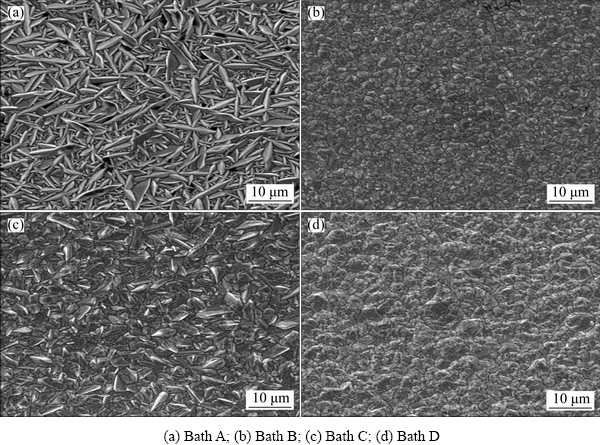
Fig. 4 SEM images of copper films produced with different electrolytes at 2 A/dm2
3.6 Morphological studies of copper deposits
The surface morphologies of the copper deposits from different formulations were examined by SEM and are displayed in Figs. 4(a)-(d). Figure 4(a) shows the deposits prepared without additive (Bath A) at 2 A/dm2. We can observe that a homogeneous leaf like crystal is uniformly arranged on the entire surface and clusters of crystalline are dispersed on the coating. It suggests that additive free copper bath exhibits relatively low crystallization overpotential and relatively high exchange current densities. Figure 4(b) shows that SEM image of electrodeposited copper obtained from Bath B containing thiamine hydrochloride has modified the shape of the grains with more regular and smooth surface morphology. It suggested that the coatings are compact, sepals like smooth, fine grained morphology and very reflective and no evidence of any nodules. Moreover, grain modifiers or brighteners reduce the nucleation overpotential and promote secondary nucleation events, often referred to as frequent 3D nucleation on the top of existing grains [27]. It apparently indicates that sulfur-containing compounds significantly alter the nucleation and growth processes during electrodeposition, corresponding surface morphology changed [28]. In the presence of saccharin (Bath C), grain size is the same as for the additive-free copper deposit. Moreover, the saccharin is usually used as a primary brightener for electrodeposition of metals and alloys. This observation confirms that saccharin has a slight effect on copper electrodeposition and does not modify the grain size and the similar result was observed by QUINET et al [3]. With addition of 4-amino 3-hysroxy naphthale-sulphonic acid (Bath D), a different surface morphology (Fig. 4(d)) was observed. On the other hand, additives would adsorb on the surface and inhibit the electroreduction of metal ions.
4 Conclusions
The copper nanocrystalline was prepared from acetate solution by electrodeposition technique. Smooth and adherent nanocrystalline copper deposits were prepared from acetate-based formulations containing thiamine hydrochloride, saccharin and 4-amino 3-hysroxy naphthale-sulphonic acid as additives. Acetate-based bath formulations showed high cathode current efficiency and throwing power. Crystallographic studies revealed that deposits yielded without additive and 4-amino 3-hysroxy naphthale-sulphonic acid containing (Bath D) showed the highest reflection of (220) plane. Whereas, the deposits yielded from Bath B and Bath C containing thiamine hydrochloride and saccharin additives displayed preferential orientation of (111) plane. The crystal size calculation based on XRD data revealed that the deposits prepared from the Bath B containing thiamine hydrochloride and Bath D containing 4-amino 3-hysroxy naphthale-sulphonic acid displayed the smallest grain size. Whereas the Bath A (without additive) and Bath C showed that grain size was not significantly varied, but the deposit yielded from saccharin containing Bath C is brighter. Hence, saccharin acted as primary brightener but not grain modifier. Texture coefficient analysis revealed that all the deposits paralleled to the surface. Hence, the texture coefficient values are greater than unity. SEM studies revealed that deposits obtained from thiamine hydrochloride (Bath B) 4-amino 3-hysroxy naphthale-sulphonic acid (Bath D) are more compact and fine grain structure and the grain refinement were brought about by the additives.
References
[1] LOWENHEIM F A. Modern electroplating [M]. 5th edition. New York, USA: John Wiley and Sons, 2010.
[2] SCHLESINGER M, PAUNOVIC M. Modern electroplating [M]. New York: John Wiley and Sons, Inc, 2000.
[3] QUINET M, LALLEMAND F, RICQ L, HIHN J Y, DELOBELLE P, ARNOULD C, MEKHALIF Z. Influence of organic additives on the initial stages of copper electrodeposition on polycrystalline platinum [J]. Electrochimica Acta, 2009, 54: 1529-1536.
[4]  T I, OROSZ V, FEKETE Z, SZIRMAI G. Direct cathodic deposition of copper on steel wires from pyrophosphate baths [J]. Materials Science and Engineering, 2012, 372: 99-110.
[5] HASAN M, ROHAN J F. Cu electrodeposition from methanesulfonate electrolytes for ULSI and MEMS applications [J]. Journal of the Electrochemical Society, 2010, 157: D278-D282.
[6] CAO H, HANG T, LING H, LI M. Behaviors of chloride ions in methanesulfonic acid bath for copper electrodeposition of through-silicon-via [J]. Journal of the Electrochemical Society, 2013, 160: D146-D149.
[7] ZHU P, WANG L Y, CHEN Y, ZHOU M, ZHOU J. Electrodeposition of copper coating on AZ31 magnesium alloy [J]. Surface Engineering, 2012, 28: 796-799.
[8] BALASUBRAMANIAN A, SIRKUMAR D S, RAJA G, SARAVANAN G, MOHAN S. Effect of pulse parameter on pulsed electrodeposition of copper on stainless steel [J]. Surface Engineering, 2009, 25: 389-392.
[9] MANTRY S, BEHERA D, SATAPATHY A, JHA B B, MISHRA B K. Deposition on plasma sprayed copper slag coatings on metal substrates [J]. Surface Engineering, 2013, 29: 222-227.
[10] OISHI T, YAGUCHI M, KOYAMA K, TANAKA M, LEE J C. Effect of additives on monovalent copper electrodeposition in ammonical alkaline solutions [J]. Hydrometallurgy, 2013, 133: 58-63.
[11] ONICIU L, MURESAN L. Some fundamental aspects of leveling and brightening in metal electrodeposition [J]. Journal of Applied Electrochemistry, 1991, 12: 565-574.
[12] LOW C T, WALSH F C. Normal and anomalous electrodposition of tin-copper alloys from methanesulphonic acid bath containing perfluorinated cationic surfactant [J]. Transactions of the Institute of Metal Finishing, 2008, 86: 315-325.
[13] SEKAR R, JAGADESH K K, RAMESH BAPU G N K. Electrodeposition and characterization of copper deposits from non-cyanide electrolytes [J]. Surface Engineering, 2015, 31: 433-438.
[14] ABD EL REHIM S S, SAYYAH S M, E L DEEB M M. Electroplating of copper films on steel substrates from acidic gluconate baths [J]. Applied Surface Science, 2000,165: 249-254.
[15] IBRAHIM M A M. Copper electrodeposition from non-polluting ammonia baths [J]. Plating and Surface Finishing, 2000, 87: 67-72.
[16] SIVASAKTHI P, SEKAR R, RAMESH BAPU G N K. Electrodeposition and characterization of copper from cyanide free alkaline glycerol complex baths [J]. Transactions of the Institute of Metal Finishing, 2015, 93(1): 32-37.
[17] SEKAR R, JAYAKRISHNAN S. Effect of sulphonic acids on electrodeposition of nickel and its structural and corrosion behavior [J]. Transactions of the Institute of Metal Finishing, 2012, 90: 324-329.
[18] SEKAR R, JAGADESH K K, RAMESH BAPU G N K, Electrodeposition and characterization of zinc from alkaline zincate solutions [J]. Transactions of the Institute of Metal Finishing, 2015, 93: 133-138.
[19] SEKAR R, JAGADESH K K, RAMESH BAPU G N K. Microstructure and corrosion behavior of electrodeposited nanocrystalline nickel prepared from acetate bath [J]. Korean Journal of Chemical Engineering, 2015, 32: 1-7.
[20] SEKAR R, JAYAKRISHNAN S. Characterstics of zinc electrodeposits from acetate solutions [J]. Journal of Applied Electrochemistry, 2005, 36: 591-597.
[21] B571-584. ASTM test method: Adhesion of metallic coatings [S].
[22] KLUG H P, ALEXANDER L. X-ray diffraction procedures for polycrystalline and amorphous materials [M]. New York: John Wiley and Sons, 1980.
[23] SCHERRER P. Bestimmung der grosse und der inneren struktur von kolloidteilchen mittles rontgenstrahlen, nachrichten von der gesellschaft der wissenschaften, gottingen mathematisch- Physikalische Klasse, 1918, 2: 98-100.
[24] APARICO J L O, MEAS Y, TREJO G, ORTEGA R, CHAPMAN T W, CHAINET E. Effects of organic additives on zinc electrodeposition from alkaline electrolytes [J]. Journal of Applied Electrochemistry, 2013, 43: 289-300.
[25] MOFFAT TP, BONEVICH J E, HUBER W H, STANISHEVSKY A, KELLY D R, STAFFORD G R, KELLY D R. Superformal electrodeposition of copper in 500-90 nm features [J]. Journal of Electrochemical Society, 2000, 147: 4524-4535.
[26] Joint Committee on Power Diffraction Standards. International Centre for Diffraction file, PDF-2 Database sets 1-49 [DB]. Pennsylvania, PA, USA, 2000.
[27] ADCOCK P A, ADELJU S B, NEWMAN O M G. Measurements of polarization parameters impacting on electrodeposits morphology 1: Theory and development of technique [J]. Journal of Applied Electrochemistry, 2002, 32: 1101-1107.
[28] KELLY J J, TIAN C, WEST A C. Levelling and microstructural effect of additives for copper electrodeposition [J]. Journal of the Electrochemical Society 1999, 146: 2540-2545.
R. SEAKR
Electroplating and Metal Finishing Technology Division, Central Electrochemical Research Institute, Karaikudi-630 006, Tamil Nadu, India
ժ Ҫ���ڴ�ͳ�������ͭ�м��������һ�ֿ�ѡ��ĵ��Һ���ӻ����Ѻõ���������Һ�е����ͭ���õ��Һ������ͭ�������ơ����������ɡ�����ά���ء��Ǿ���4-����-3-�ǻ�-1-������Ϊ�������Һ�����Ӽ������÷����ڶ��ɼ�����������Ч�ʣ���ʹ��Haring-Blum���ȷ����Һ�еĽ����ֲ��ȡ���Щ���Ӽ�Ӱ���˳���ͭ��Ĥ�ı�����ò������SEM��XRD�ֶη����侧���ߴ硣XRD�ױ��������ͭ�Ƕྦྷ����������ṹ������Debye-Scherrer��ʽ���㱡Ĥ�ľ�����С������ߴ���������Һ���Ӽ������õ��IJ��������С�ľ����ߴ硣֯��ϵ���������������е�ͭ����Ĥ���Ƕྦྷ�ṹ����������ȡ��ƽ���ڱ��档���Ӽ������˾��ȵ�����ױ�����ò�;���ϸ����
�ؼ��ʣ������Σ�ͭ����������Ӽ�
(Edited by Xiang-qun LI)
Corresponding author: R. SEAKR; Tel: +91-4565 241572: +91-9940874641; Fax: +91-4565-7779; E-mail: grsek2004@yahoo.com
DOI: 10.1016/S1003-6326(17)60164-X

