Trans. Nonferrous Met. Soc. China 23(2013) 201-207
Force analysis and experimental study of pure aluminum and Al-5%Ti-1%B alloy continuous expansion extrusion forming process
Fu-rong CAO1, Jing-lin WEN1, Hua DING1, Zhao-dong WANG2, Ying-long LI1, Ren-guo GUAN1, Hui HOU1
1. College of Materials and Metallurgy, Northeastern University, Shenyang 110819, China;
2. State Key Laboratory of Rolling and Automation, Northeastern University, Shenyang 110819, China
Received 9 November 2011; accepted 30 March 2012
Abstract: The deformation zone of CONFORM extrusion was divided into primary gripping zone, gripping zone, conical expansion chamber zone, cylindrical zone and sizing zone of die, and corresponding force equilibrium equations were established using the Slab method. The deformation force formulae of CONFORM machine at any wrapping angle with an expansion chamber were obtained. Experiment on pure aluminum and Al-5%Ti-1%B alloy was conducted on the CONFORM machine self-designed. The resistance to deformation of Al-5%Ti-1%B alloy at the deformation temperature of 400 ��C and the strain rate of 3.07 s-1 was measured to be 50 MPa using Gleeble-1500 thermal simulation machine. The calculation results of deformation forces for CONFORM process with an expansion chamber for pure aluminum and Al-5%Ti-1%B alloy were given. The experimental CONFORM radial force is in agreement with the radial force obtained by theoretical formula.
Key words: aluminum; aluminum alloy; continuous extrusion; expansion chamber; resistance to deformation
1 Introduction
GREEN [1] invented the CONFORM process, continuous extrusion forming process. Contrary to traditional extrusion, CONFORM extrusion turns the friction resistance between billet and container into the driving force of billet deformation. As long as various billets or feedstock of aluminum, copper, polymeric material rod, particles and powders are fed continuously into the entrance of CONFORM machine, and various products such as wire, rod, profile, and tube that conform to the requirements can be turned out continuously at the exit of extrusion die. Since the appearance of CONFORM, its application in major industrial and scientific fields is increasing. MITCHELL [2,3] showed that CONFORM was a commercially viable method of producing hollow sections and tubing for air conditioning, refrigeration and cable television applications, and reviewed the manufacture of wire and conductor using the CONFORM process. PARDOE [4] discussed the CONFORM process of aluminum tube from rod and scrap and presented in detail the mechanical properties of tubes. HAWKES and MORGAN [5] reported the CONFORM extrusion of copper or aluminum solid sections and the sheathing or cladding operations. CHURCH [6] introduced the application of CONFORM to produce sheathe cable in Europe and made wide variety of solid and hollow shapes, and the feedstock might be rod, granules, powder and molten metal. He pointed out the development of an expansion chamber in which the cross-section of profile is larger than that of the feedstock. LANGERWEGER and MADDOCK [7] presented an innovative continuous casting and extrusion (CASTEX) machine with an expansion chamber through which products whose sections are larger than feedstock could be produced. MADDOCK [8] discussed the application of rod feed CONFORM and granule feed CONFORM and introduced the CASTEX process with an expansion chamber. Recently, RAAB et al [9] and XU et al [10] reported the application of ECAP- CONFORM, a combination of equal-channel angular pressing (ECAP) with CONFORM, to fabricate ultrafine grained aluminum wire and Al-6061 rod. However, no work has been reported about the application of CONFORM machine with an expansion chamber to perform the extrusion of pure aluminum and Al-5%Ti- 1%B alloy in China except Northeastern University.
The theoretical simulation on CONFORM or CASTEX process is increasing. PENG et al [11] investigated the plastic flow of the metal in the experimental simulation using Moire method and found the existence of an intense internal shear band in the plastic deformation zone. Numerous FEM simulations have been carried out to elucidate the effects of process parameters on defects. PENG et al [12] predicted the processes of defect initiation and development during CONFORM process and obtained some critical technological parameters such as leak gap, friction factor, and groove width. KIM et al [13] utilized the DEFORM FEM software to investigate the effects of several process parameters on the process characteristics, such as material flow, defect occurrence, temperature and effective strain distribution, and suggested a qualitative guide for the optimal CONFORM process design. CHO and JEONG [14-16] addressed a parametric investigation on the occurrence of the surface defect in CONFORM process and carried out FEM simulation experiments to parametrically analyze their effects on the surface defect occurrence. Also, they utilized FEM analysis to perform the parametric investigation on the curling phenomenon and numerically examine the effects of the wheel diameter on the surface separation and curling phenomenon. Upper bound analyses were applied to the CONFORM or CASTEX process to correlate the deformation power with the process parameters. CAO et al [17] derived the upper bound driving power equation for CASTEX process using continuous velocity field. KIM et al [18] applied upper bound method to the CONFORM process and derived the equation for calculating the powers which was compared with FEM simulation results. Above FEM analyses deepen the understandings of various CONFORM defects and the metallic flow of deformation body so as to control the CONFORM process. The equations of upper bound analyses help to determine the driving power of CONFORM or CASTEX process and provide a basis for choosing CONFORM or CASTEX equipment and designing tools. Although CONFORM process and simulation have been reported as described above, little information appears available on the mechanics analysis of CONFORM extrusion with an expansion chamber at home and aboard.
In the present work, based on the die with an expansion chamber designed by ourselves, we derive the extrusion stress formula in the expansion chamber. On the basis of wheel groove stress analysis, the tangential force and radial force of wheel groove driving for CONFORM process at any wrapping angle are determined. In the meantime, the deformation resistance of Al-5%Ti-1%B alloy is determined experimentally.
2 Mechanics analysis of CONFORM process with expansion chamber
The schematic diagram of CONFORM process is shown in Fig. 1. Feedstock enters from the entrance of extrusion wheel into the extrusion cavity formed by the wheel groove and grip segment. Under the action of friction force imposed by the two sides of wheel groove and the bottom surface, the feedstock is deformed in the extrusion cavity and is extruded out of extrusion die to obtain the product in required shape and properties.
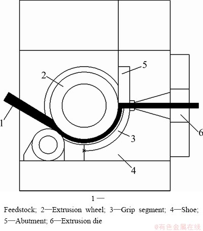
Fig. 1 Schematic diagram of CONFORM process
According to the deformation characteristics of feedstock, the deformation process is divided into five deformation zones: primary gripping zone, gripping zone, conical expansion chamber, cylindrical container and sizing zone of die, as shown in Fig. 2. Expansion chamber consists of the conical expansion chamber and the cylindrical container. We perform mechanics analysis zone by zone from the beginning of sizing zone of die to the wheel entrance.
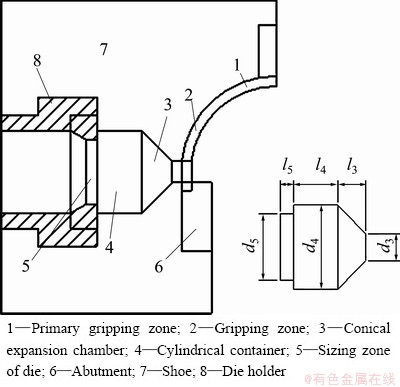
Fig. 2 CONFORM deformation zone with expansion chamber
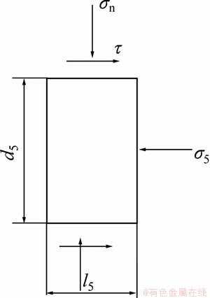
Fig. 3 Stress analysis of sizing zone
2.1 Sizing zone of die
The stress analysis in the sizing zone is shown in Fig. 3. In Fig. 3, ��n is the stress caused by the recovery of elastic deformation force and is assumed to be approximately equal to the resistance to deformation (��s). Because of relative movement between the billet and the sizing zone of die, friction stress, ��, occurs and conforms to Coulomb law of friction.
 (1)
(1)
Take the horizontal direction as the x coordinate axis. According to force equilibrium equation, one gets
 (2)
(2)
Insert formula (1) into formula (2), one gets the acting stress of sizing zone on cylindrical container in sizing zone of die:
��5=4fs��sl5/d5 (3)
where fs is the coefficient of friction between the billet and the sizing zone of die; ��s is the resistance to deformation of material; l5 is the length of sizing zone of die; d5 is the diameter of sizing zone of die.
2.2 Cylindrical container
In cylindrical container, up-and-down symmetrical two dead zones exist at the boundary between the container and the conical deformation zone. Material is deformed in the conical deformation zone. The infinitesimal element chosen is shown in Fig. 4.
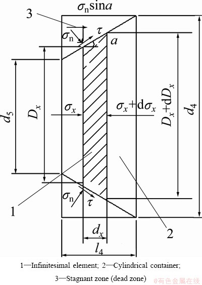
Fig. 4 Acting stresses on infinitesimal element of cylindrical container
The shear stress, ��, on the boundary surface between the dead zone and the conical deformation zone reaches the maximum value:  . The force equilibrium differential equation along horizontal
x-axis direction is as follows:
(��x+d��x) (Dx+dDx)2��/4-��x��Dx 2/4-��nsin��1(��Dxdx)/cos��1-��s��Dx dx =0 (4)
In consideration of dDx/2=(dx)tg��1, and Tresca yield criterion ��n-��x=��s is substituted into Eq. (4).
Then
d��x=2��s(1+ctg��1)(dDx/Dx)
Integrate ��d��x=��2��s(1+ctg��1)(dDx/Dx)
We can get ��x=2��s(1+ctg��1)lnDx+C
The boundary condition is used to determine the integral constant C.
When Dx=d5, ��x=��5=4fs��sl5/d5, thus C=4fs��sl5/d5- 2��s(1+ctg��1) ln d5
When Dx=d4, ��4=fs��sl5/d5+2��s[1+ctg��1]��ln(d4/d5).
Thus, the acting stress of cylindrical container on the conical expansion chamber is
��4=fs��sl5/d5+2��s(1+ctg��1)ln(d4/d5) (5)
where ��1=tg-1[(d4-d5)/(2l4)], d4 is the diameter of cylindrical container and l4 is the length of cylindrical container.
2.3 Conical expansion chamber
The expansion chamber is conical. Its shape of deformation zone is the same as the shape of deformation zone in the cylindrical container. Similar to the treatment in section 2.2, the stress, ��3, at the boundary between the conical expansion chamber and the gripping zone perpendicular to the extrusion wheel direction is obtained.
��3=��4+2��s(1+ctg��2)ln(d4/d3) (6)
where ��2=tg-1[(d4-d5)/(2l3)] and l3 is the length of conical expansion chamber.
2.4 Primary gripping zone and gripping zone
2.4.1 Lengths of primary gripping zone and gripping zone, and stress distribution
1) Length of L1 zone
Metal fills the groove gradually. �� starts from zero and increases till f��s; ��n (tangential stress) starts from zero and increases till ��s, as shown in Fig. 5. Section A-B is taken as the stress body. The metal in this section is subjected to the friction forces on two sides of the wheel groove and the tangential force is transferred from the front metal. The friction forces of the groove bottom and the shoe on the metal which is not relevant to L1 counteract mutually.
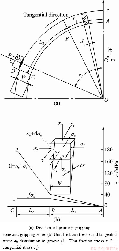
Fig. 5 Division of primary gripping zone and gripping zone and stress distribution diagram
Let the unit friction force in A-B section be ��1, so  which satisfies the boundary condition of L=0, ��1=0; L=L1, ��1=f��s. Due to the simultaneous action of friction force on both sides of wheel groove, the friction force of wheel groove on the stress body becomes
 (7)
(7)
The tangential force is  .
.
Static force equilibrium of section A-B is
 (8)
(8)
Thus, one gets
 (9)
(9)
where f is the coefficient of friction, and f is 0.5 according to Tresca yield criterion.
2) Length of L2 zone
�� is equal to f��s. The tangential stress ��n in front of the abutment increases, which causes the metal to turn the flow direction, and causes the extrusion stress produced in the extrusion direction to reach ��3 required by extruding the metal out. Let ns=��3/��s. Metal in section B-C is taken as the stress body. The metal in this section is subjected to the friction forces on two sides of the wheel groove and the tangential force ��n is transferred from the abutment. The friction forces of the groove bottom and the shoe on the metal in this section counteract mutually.
The tangential force equilibrium in section B-C is
 (10)
(10)
Since the effect of friction force on yield can be neglected, the plasticity criterion diagram in front of the abutment is shown in Fig. 6 in which Z axis is the axial direction of CONFORM wheel.
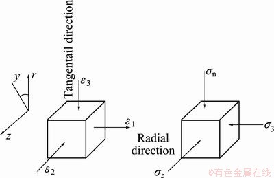
Fig. 6 Plasticity criterion diagram
According to Tresca yield criterion of the maximum shear stress, there is:
 (11)
(11)
Insert f(0.5), formula (11) and ns=��3/��s into Eq. (10), one gets
 (12)
(12)

2.4.2 Determination of CONFORM extrusion force
The CONFORM extrusion force means the tangential force Pt and the radial force Pr sustained by the wheel groove of CONFORM wheel. The force diagram of wheel groove is shown in Fig. 7.
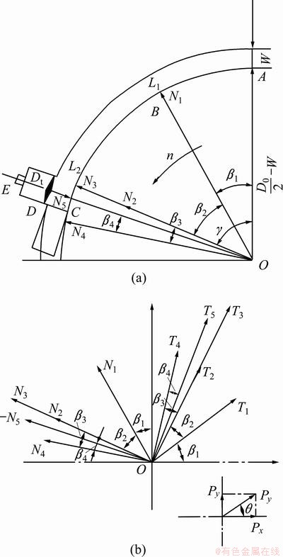
Fig. 7 Force diagram of wheel groove for CONFORM extrusion
Acting forces on the side faces and the bottom surface of L1 zone, there are
 ;
; 
Acting forces on the side faces and the bottom surface of L2 zone, there are
 ;
; 
Flash forces caused by the clearance are
 ;
; 
Flash force on the three sides of abutment is
 =3f��sWZ; N4=3��sWZ
Acting force of conical expansion chamber on wheel groove, there are
T5=fN5; N5=(1/4)(��3-��s)��
where b is the length of single side flash; Z is the length of flash caused by the leakage between the abutment and the wheel groove. Because (1/4)����s is included in N3, it is subtracted when N5 is determined.
Thus, the tangential force of deformation material acting on wheel groove is
Pt=f��sWL1+(1/2)f��sW L1+3f��sWL2+2bf��sL2+3f��sWZ= f��s(1.5Wl1+3Wl2+2bl2+2WZ) (13)
The radial force of deformation material acting on the wheel groove is determined by
Pr=
��=arc ctg (14)
(14)
where Px is the horizontal component, Py is the vertical component and �� is the direction angle.
For convenient deduction, matrix transformation is applied to dealing with the transformation from the Oiyixi coordinate system of acting forces of wheel groove to the Oyx coordinate system of wheel center, as shown in Fig. 8.
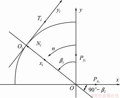
Fig. 8 Transformation of coordinate system of wheel groove acting forces (i=1, 2, 3, 4, 5)
From Oi��O, one gets
 (i=1, 2, 3, 4, 5)
Combining above formula for i, one can get

Let
{P}=(Px Py)T,
{G}=(T1T2+T3T4T5N1N2+N3N4N5)T

So {P}=[A]{G}.
Thus, it can be seen that column matrix of radial force is the product of CONFORM angle matrix and wheel groove acting force column matrix.
So, the horizontal component Px and the vertical component Py of radial force Pr are obtained.
Px=N1sin��1+(N2+N3)sin(��1+��2)+ N4sin(��+��4)+ N5sin��+
T1cos��1+( T2+ T3)cos(��1+��2)+ T4 (��+��4)+T5cos��
Py=-N1cos��1-(N2+N3)cos(��1+��2)-N4cos(��+��4)-N5sin��+
T1sin��1+(T2+T3)sin(��1+��2)+T4sin(��+��4)+T5sin�� (15)
where ��1=[�� (0.5Dl-W)-L1-2L2+Dt]/(Dt-2W); ��2=(L1+ L2)/(Dl-2W); ��3=(L2+Z)/(Dl-2W); ��4=(Dt+Z)/(Dl-2W); ��=��1+��2+��3-��4.
where Dl is the wheel diameter, W is the height or depth of groove, Dt=d3 and �� is the wrapping angle in rad.
Formulae (13)-(15) are the derived formulae for radial CONFORM extrusion at any wrapping angle.
3 Experimental process and calculation results
3.1 Experimental process
CONFORM tests of pure aluminum and Al-5%Ti-1%B alloy were conducted on the self- designed CONFORM machine with an expansion chamber. The wheel diameter was 350 mm. Trapezoid billet with dimensions of 23 mm��21 mm was fed into the rotary extrusion wheel groove and rectangular solid product with dimensions of 25 mm��35 mm was obtained by extrusion deformation. In the shoe, a sensor was mounted at the outlet side of extrusion wheel to measure the radial force. Prior to measurement of the radial force, the sensor was calibrated by DY-15 stabilized voltage power supply, YD-15 dynamic electrical resistance strain gauge and SC-16 light ray recording oscillograph.
Extending extrusion of pure aluminum was conducted easily at room temperature. Because the resistance to deformation of Al-5%Ti-1%B alloy processed by continuous extending extrusion is large, and the metallic filling of the extending chamber at room temperature requires metallic fluidity, it is difficult to conduct the continuous extending extrusion of Al-5%Ti-1%B alloy at room temperature. Therefore, the trapezoid billet of Al-5%Ti-1%B alloy and pure aluminum were heated to 400 ��C for deformation. The resistance to deformation at deformation temperature was obtained on Gleeble-1500 thermal simulating machine. The resistance to deformation of Al-5%Ti- 1%B alloy at the deformation temperature of 400 ��C with a strain rate of 3.07 s-1 was obtained to be 50 MPa. According to Ref. [19], the resistance to deformation of pure aluminum at the deformation temperature of 400 ��C with a strain rate of 3.07 s-1 was obtained to be 23.4 MPa, and the coefficient of friction is 0.275. When a solid profile of non-round cross section was extruded out of the die, equivalent diameter could be obtained by the method of equivalent cross-sectional area[19], and then the derived extrusion stress formulae of a round bar were used. Therefore, in extrusion die, the rectangular solid profile of 25 mm��35 mm was treated equivalently into a round bar whose equivalent diameter is 33 mm.
3.2 Calculation results
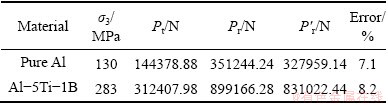
The calculation parameters are Dl=350 mm, l5=4 mm, d5=33 mm, d4=80 mm, d3=30 mm, fs=0.275, ��s(Al-Ti- B)=50 MPa,��s(Al)=23.4 MPa, ��=120��.
The calculation results are shown in Table 1. The experimental radial force is in agreement with the theoretical radial force with an error less than 10%. The derived CONFORM force formulae will provide a basis for the innovative design of CONFORM machine and tools and help to deepen the understanding of the CONFORM process.
Table 1 Comparison of calculation results with experimental radial force
4 Conclusions
1) The deformation zone of CONFORM extrusion was divided into primary gripping zone, gripping zone, conical expansion chamber zone, cylindrical zone and sizing zone of die, and corresponding force equilibrium equations were established using the slab method. The deformation force formulae of CONFORM machine at any wrapping angle with an expansion chamber were obtained.
2) Experiment on pure aluminum and Al-5%Ti- 1%B alloy was conducted on the CONFORM machine self-designed. The resistance to deformation of Al-5%Ti-1%B alloy at the deformation temperature of 400 ��C and the strain rate of 3.07 s-1 was measured as 50 MPa. The calculation results of deformation forces for CONFORM process with an expansion chamber for pure aluminum and Al-5%Ti-1%B alloy were given. The experimental CONFORM radial force is in agreement with the radial force obtained by theoretical formula.
References
[1] GREEN D. The continuous extrusion forming of wire sections [J]. Journal of the Institute of Metals, 1972, 100(8): 296-300.
[2] MITCHELL K J. Tube manufacture by the CONFORM process [J]. Metallurgia, 1982, 8(9): 448-449.
[3] MITCHELL K J. Production of wire and allied products by the ��conform�� process [J]. Metallurgia, 1982, 8(11): 584-589.
[4] PARDOE J A. CONFORM��The revolutionary process for continuous extrusion of aluminum tube from rod and scrap [J]. Light Metal Age, 1984, 42(3-4): 6-12.
[5] HAWKES D J, MORGAN R E. CONFORM extrusion [J]. Wire Industry, 1991, 58(6): 323-326.
[6] CHURCH F L. Extrusion goes continuous; process promises economies [J]. Modern Metals, 1984, 40(11): 34-40.
[7] LANGERWEGER J, MADDOCK B. Production of aluminum wire directly from the molten metal [J]. Wire World International, 1986, 28(11-12): 179-181.
[8] MADDOCK B. Aluminum rod and other products by CONFORM [J]. Wire Industry, 1987, 54(12): 728-731.
[9] RAAB G J, VALIEV R Z, LOWE T C, ZHU Y T. Continuous processing of ultrafine grained Al by ECAP�CCONFORM [J]. Materials Science and Engineering A, 2004, 382(1-2): 30-34.
[10] XU C, SCHROEDER S, BERBON P B, LANGDON T G. Principles of ECAP�CCONFORM as a continuous process for achieving grain refinement: Application to an aluminum alloy [J]. Acta Materialia, 2010, 58(4): 1379-1386.
[11] PENG D S, YAO B Q, ZUO T Y. The experimental simulation of the deformation behavior of metals in the CONFORM process [J]. Journal of Materials Processing Technology, 1992, 31(1-2): 85-92.
[12] PENG Y, RUAN X, ZUO T. Defect prediction during CONFORM process by FEM [J]. Journal of Materials Processing Technology, 1994, 45: 539-543.
[13] KIM Y H, CHO J R, JEONG H S, KIM K S, YOON S S. A study on optimal design for CONFORM process [J]. Journal of Materials Processing Technology, 1998, 80-81(8): 671-675.
[14] CHO J R, JEONG H S. Parametric investigation on the surface defect occurrence in CONFORM process by the finite element method [J]. Journal of Materials Processing Technology, 2000, 104(3): 236-243.
[15] CHO J R, JEONG H S. Parametric investigation on the curling phenomenon in CONFORM process by three-dimensional finite element analysis [J]. Journal of Materials Processing Technology, 2001, 110(1): 54-60.
[16] CHO J R, JEONG H S. CONFORM process: Surface separation, curling and process characteristics to the wheel diameter [J]. Journal of Materials Processing Technology, 2003, 136(1-3): 217-226.
[17] CAO F R, SHI Z Y, WEN J L. Upper-bound approach analysis of driving power of wheel for CASTEX [J]. Transactions of Nonferrous Metals Society of China, 1999, 9(1): 99-104.
[18] KIM Y H, CHO J R, KIM K S, JEONG H S, YOON S S. A study of the application of upper bound method to the CONFORM process [J]. Journal of Materials Processing Technology, 2000, 97(1-3): 153-157.
[19] WEN Jing-lin. Metallic extrusion and drawing technology [M]. Shenyang: Northeastern University Press, 1996: 57-59. (in Chinese).
����չǻ�Ĵ�����������Ͻ�������ѹ���ķ�����ʵ���о�
�ܸ���1���¾���1���� ��1�����Ѷ�2����Ӣ��1�����ʹ�1���� ��1
1. ������ѧ ������ұ��ѧԺ������ 110819��
2. ������ѧ �����������Զ��������ص�ʵ���ң����� 110819
ժ Ҫ����CONFORM��ѹ�ı��������ֳɳ�ʼ�н������н�����Բ����չǻ����Բ���μ�ѹͲ���Ͷ�������������Ӧ��������������ƽ�ⷽ�̣�����˴���չǻ���������������ѹ���̵ı�������ʽ����������Ƶ�������ѹ���϶Դ�����������Ͻ�(Al-5%Ti-1%B)����ʵ�顣����Gleeble-1500��ģ��ʵ���ʵ��õ�������Ͻ��ڱ����¶�400 ��C��Ӧ������3.07 s-1�����µı��ο���Ϊ50 MPa������õ�������������Ͻ����չǻ������ѹ�ı�������ʵ���õ�������ѹ�����������ۼ����������ѹ������һ�¡�
�ؼ��ʣ��������Ͻ�������ѹ����չǻ�����ο���
(Edited by Xiang-qun LI)
Foundation item: Projects (51034002, 50974038, 50274020) supported by the National Natural Science Foundation of China
Corresponding author: Fu-rong CAO; Tel: +86-24-83670183; E-mail: cfr-lff@163.com
DOI: 10.1016/S1003-6326(13)62447-4

