
Effects of nitrogen content on structure and electrical properties of
nitrogen-doped fluorinated diamond-like carbon films
XIAO Jian-rong(–§Ĺ£»Ŕ)1, 2, 3, LI Xin-hai(ņÓ–¬ļ£)1, WANG Zhi-xing(Õű÷ĺ–ň)1
1. School of Metallurgical Science and Engineering, Central South University, Changsha 410083, China;
2. Department of Physics and Maths, Guilin University of Technology, Guilin 541004, China;
3. Guangxi Key Laboratory of Information Materials, Guilin University of Electronic Technology,
Guilin 541004, China
Received 10 August 2009; accepted 15 September 2009
Abstract: Nitrogen-doped fluorinated diamond-like carbon (FN-DLC) films were prepared on single crystal silicon substrate by radio frequency plasma enhanced chemical vapor deposition (RF-PECVD) under different deposited conditions with CF4, CH4 and nitrogen as source gases. The influence of nitrogen content on the structure and electrical properties of the films was studied. The films were investigated in terms of surface morphology, microstructure, chemical composition and electrical properties. Atomic force microscopy (AFM) results revealed that the surface morphology of the films became smooth due to doping nitrogen. Fourier transform infrared absorption spectrometry (FTIR) results showed that amouts of C=N and C°‘N bonds increased gradually with increasing nitrogen partial pressure r (r=p(N2)/p(N2+CF4+CH4)). Gaussian fit results of C 1s and N 1s in X-ray photoelectron spectra (XPS) showed that the incorporation of nitrogen presented mainly in the forms of ¶¬-C3N4 and a-CNx (x=1, 2, 3) in the films. The current-voltage (I-V) measurement results showed that the electrical conductivity of the films increased with increasing nitrogen content.
Key words: fluorinated diamond-like carbon films; nitrogen doping; structure; electrical properties
1 Introduction
Fluorinated amorphous carbon (a-C?F) films are a kind of very interesting materials due to their outstanding properties, such as high hardness, low dielectric constant, low friction coefficient and wide optical band gap[1-5]. These films have been used in industry as dielectric interlayer in ultra-large scale integration technology devices, protective coatings on magnetic hard disks and optical devices coatings. The a-C?F films have excellent electrical and optical properties, good thermal stability and industrial process ability, due to C-F bonding and highly cross-linked structures of the films[6-8]. The thermal stability of the films depends strongly on the degree of cross linking in the carbon network, and the highly cross linking can be obtained by increasing the deposition power, deposition temperature, annealing temperature, and so on[1, 6, 9-10]. Ways to further improve the properties of this material include incorporation of other elements and adjustment of the atomic content in the films[11-12]. LIU et al[10] found that the fraction of aromatic ring structures increases and the thermal stability of the films is strengthened with the increase of N2 content. And nitrogen doping is a feasible approach to improve the thermal stability of films. YOKOMICHI and MASUDA[13] reported that a-C?F?N films had a low dimensional structure without crystalline regions, and the dangling bond density decreased and the optical band gap was approximately constant with increasing nitrogen concentration.
However, the structure and electrical properties are not very clear after the nitrogen doping of the a-C?F films. In this work, nitrogen-doped fluorinated diamond-like carbon (FN-DLC) films were deposited by radio frequency plasma enhanced chemical vapor deposition (RF-PECVD) using CF4, CH4 and N2 as source gases. The purpose of this work is to investigate the relationships between the local bonding configurations of the N atoms from the analysis of the flourier transform infrared absorption spectrometry and X-ray photoelectron spectra in terms of C-N bonds vibration modes. The effects of nitrogen incorporation on the electrical properties of the films were mainly discussed.
2 Experimental
FN-DLC films were deposited on silicon (100) substrates by the radio frequency plasma enhanced chemical vapor deposition (RF-PECVD). The experimental equipment had been described previously in details[14]. The films were prepared under the following conditions: discharge power 100-120 W, and deposition temperature 80-100 °ś. The source gases were CF4, CH4, and N2. The CF4 and CH4 flow rates were fixed at 30 and 10 mL/min, respectively. The nitrogen partial pressure r (r=p(N2)/p(CF4+CH4+N2)) was varied from 0 to 0.33. That is to say, the N2 gas flow was varied from 0 to 20 mL/min. Prior to deposition, the vacuum chamber was evacuated to 1.0°Ń10-3 Pa. Before loading into the chamber, the substrates were cleaned in an ultrasonic bath of acetone and methanol for 10 min to remove residual organic contaminants, respectively, and then washed with deionized water and dried by blowing nitrogen gas.
In order to investigate the content of N and the electrical properties of the films, the surface morphology of the films was analyzed by NT-MDT type atomic force microscope (AFM). The chemical bonding configurations were characterized by a NEXUS 470 Fourier-transformed infrared spectrometer (FTIR). Information about the chemical bonding and the elemental composition of the films was obtained by X-ray photoelectron spectrometer (XPS). The effect of the doping nitrogen on the current-voltage (I-V) characteristics of the films was investigated by a micro-current instrument.
3 Results and discussion
3.1 Morphology of films
In order to investigate the effect of nitrogen doping on the surface morphology of FN-DLC films, the AFM images of the films grown with variation of nitrogen partial pressure of r=0, r=0.20 and r=0.33 are shown in Fig.1. The discharge power and temperature were fixed to be 100 W and 100 °ś, respectively. The root mean square (RMS) surface roughness of the films deposited at a higher nitrogen partial pressure of r=0.33 is 6.173 nm, as shown in Fig.1(a), which is larger than that deposited at lower nitrogen partial pressure, as shown in Fig.1(b). When the nitrogen partial pressure is r=0.20, the RMS surface roughness is 5.035 nm. Whereas, The RMS surface roughness of the films deposited at nitrogen partial pressure of r=0 is 2.358 nm, as shown in Fig.1(c). It is surprising that the smoothest film is the one grown at the lowest nitrogen partial pressure of r=0. From the image of the surface as shown in Fig.1(a), it can be seen that the films have tightly packed configuration and smooth surface morphology. Those observations suggest that the films grown at lower nitrogen partial pressures by RF-PECVD were bombarded by energetic particles, which make the surface energy of the films decrease. That is to say, the surface morphology of the films becomes smooth due to doping nitrogen.
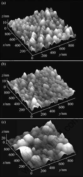
Fig.1 AFM images of films deposited at various nitrogen partial pressures: (a) r=0.33; (b) r=0.20; (c) r=0
3.2 FTIR analysis of films
The changes in chemical bonds of the FN-DLC films with various nitrogen partial pressures are shown in Fig.2. The films were deposited at 120 W and 100 °ś in a total pressure 6.2-7.0 Pa. It is obvious that the chemical bonding structures were strongly influenced by nitrogen partial pressure. As shown in Fig.2, the strong peak at around 1 100 cm-1 corresponds to CFx (x=1, 2, 3) groups vibrations, CF(1 030 cm-1, 1 070 cm-1), CF2 (1 050 cm-1, 1 160 cm-1, 1 220 cm-1) and CF3 (980 cm-1, 1 340 cm-1)[6, 15]. The peak approximately at 1 600 cm-1 corresponds to the unsaturated double bonds C=C and F2C=C. The peak at 1 710 cm-1 is associated to aromatic C=C stretching or F2C=C stretching vibrations. The peaks at 1 634 cm-1 and 1 694 cm-1 can be attributed to the stretching of olefinic C=C and C=N[15-16]. Usually, C=N stretching frequency occurs in the range of 1 650-1680 cm-1[6]. Also, it is observed that the absorbance corresponding to C°‘N bond at 2 200 cm-1 appears at the nitrogen partial pressure of r=0.20, while the absorbance for C°‘N bond is not found when r=0. In a word, the results demonstrate that the nitrogen has been doped in the films, and nitrogen has combined with carbon atoms to form a chemical bond of C=N and C°‘N.
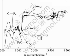
Fig.2 FTIR spectra of FL-DLC films deposited at various nitrogen partial pressures
In addition, the relative molar concentration of nitrogen, fluorine and carbon can also been estimated from the integrated absorbance of the band in the films. Here, the molar concentration was obtained by the Beer°Įs law[17]:
 (1)
(1)
where nx is the concentration of atom i; A is the proportionality factor; and ¶Ń(¶ō) is the absorption coefficient at frequency ¶ō. By Eq.(1), nitrogen, fluorine and carbon molar concentrations of the films are calculated and then the nitrogen-to-carbon molar ratio of the films is obtained.
3.3 XPS analysis of films
Fig.3 shows a typical XPS spectrum of FN-DLC films deposited by RF-PECVD. The peaks at 286, 402, and 689 eV can be due to the photoelectrons exited from the C 1s, N 1s, and F 1s levels, respectively[18]. This indicates that the deposited films were mainly composed of carbon, nitrogen and fluorine atoms. Meanwhile, there is a peak at 535 eV in the XPS spectrum, which is due to photoelectrons exited from the O 1s. The O element in the films come from two tracks: 1) there is some H2O remainder in the vacuum chamber before deposition, and it is involved in reaction when the films grow; 2) the sample surface of FN-DLC films is oxidized by O2 before XPS test. Fitting the XPS spectra using Gaussian distribution, the abundance of the C-F and C-N bonding can be obtained. The following factors were considered in the curve-fitting process. The C 1s peak was assumed to consist of two peaks, the sp3 peak and sp2 peak[18]. As seen in Fig.4(a), the two fitting peaks at 287 and 289 eV correspond to the sp2 peak and sp3 peak, respectively. The N 1s peak was assumed to consist of two peaks, the N-sp3C peak and N-sp2C peak[19]. Fig.4(b) shows a typical fitted result of the FN-DLC films. According to the studies of WU et al[19] and MARTON et al[20], the peak at 398 eV was associated with the bond of N to sp3C of the ¶¬-C3N4; while the peak at 400 eV corresponds to the bond of a-CNx (x=1, 2, 3). The peaks at 289 and 398 eV were taken as a pair and were assigned to C1 and N1 peaks of phase 1, which resembled those of the predicted ¶¬-C3N4 structure containing only C-N bonds. The peaks at 287 and 400 eV were taken as another pair and were assigned as C2 and N2 peaks of phase 2, which represented a-CNx phase[21].

Fig.3 XPS spectrum of typical FN-DLC films
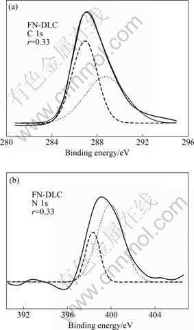
Fig.4 Fitted curves of typical FN-DLC films: (a) C 1s peak; (b) N 1s peak
3.4 Electrical conductivity of films
The current-voltage curves of FN-DLC films deposited at various nitrogen partial pressures are shown in Fig.5. It is obvious that the incorporation of nitrogen in the film changed the electrical conductivity. The electrical conductivity of the films increases with increasing nitrogen content. FTIR spectra results show that the nitrogen content in the films increases with the increase of nitrogen partial pressures. We think that the nitrogen in two kinds of films has different effects on the electrical conductivity. Because of the doping nitrogen in the films, a large amount of C and N atoms can form the C-Nx bonds, and as an impurity center it has activated the films conductivity performance, which leads to the increase of the electrical conductivity. On the other hand, when the nitrogen partial pressure increases to a certain value, the nitrogen content in the films reaches saturated states, and there appear nonconductive phases, and the nitrogen atoms do not contribute to the electrical conductivity[21].

Fig.5 Current-voltage curves of FN-DLC films deposited at various nitrogen partial pressure
4 Conclusions
1) FN-DLC films were prepared by PECVD using CH4, CF4 and N2 as source gases, at various nitrogen partial pressures. The chemical bond of the films changed after the doping nitrogen, and the bond of ¶¬-C3N4 and a-CNx (x=1, 2, 3) appeared in the films.
2) The N atoms acted as activation atoms in the films, and the electrical conductivity of the films increased with increasing nitrogen content in the films. But, when the nitrogen content in the films reached saturated states, the electrical conductivity of the films remained unchanged.
References
[1] ENDO K, TATSUMI T. Fluorinated amorphous carbon thin films grown by helicon plasma enhanced chemical vapor deposition for low dielectric constant interlayer dialectics [J]. Appl Phys Lett, 1996, 68: 2864-2866.
[2] RUBIO-ROY M, BERTRAN E, PASCUAL E, POLO M C, ANDUJAR J L. Fluorinated DLC deposited by pulse-DC plasma for antisticking surface applications [J]. Diam Relat Mater, 2008, 17: 1728-1732.
[3] FREIRE J F L, MAIA D COSTA M E H, JACOBSOHN L G . Film growth and relationship between microstructure and mechanical properties of a-C?H?F films deposited by PECVD [J]. Diam Relat Mater, 2001, 10: 125-131.
[4] WU Zhen-yu, YANG Yin-tang, WANG Jia-you. The effect annealing on electrical properties of fluorinated amorphous carbon films [J]. Diam Relat Mater, 2008, 17: 118-122.
[5] JIANG Mei-fu, NING Zhao-yuan. Structural analysis of fluorinated diamond-like carbon films by Raman and Fourier transform infrared absorption spectroscopy [J]. Acta Physica Sinica, 2004, 53(5): 1588-1593. (in Chinese).
[6] YI J W, LEE Y H, FAROUK B. Annealing effect on structural and electrical properties of fluorinated amorphous carbon films deposited by plasma enhanced chemical vapor deposition [J]. Thin Solid Films, 2003, 423: 97-102.
[7] JUNG H, PARK H. Structural and electrical properties of co-sputtered fluorinated amorphous carbon film [J]. Thin Solid Films, 2002, 420/421: 248-252.
[8] VALENTINI L, BRACA E, KENNY J M, FEDOSENKO G, ENGEMANN J, LOZZI L, SANTUCCI S. Analysis of the role of fluorine content on the thermal stability of a-C?H?F thin films [J]. Diam Relat Mater, 2002, 11: 1100-1105.
[9] XIAO Jian-rong, XU Hui, GUO Ai-min, WANG Huan-you. Study of FN-DLC films: (ĘŮ) sp structure and chemical bond analysis [J]. Acta Physica Sinica, 2007, 56(3): 1802-1808. (in Chinese).
[10] LIU Xiong-fei, ZHOU Xin, GAO Jin-ding. Influence of nitrogen doping on thermal stability of fluorinated amorphous carbon thin films [J]. Trans Nonferrous Met Soc China, 2006, 16(1): 54-58.
[11] VALENTINI L, BRACA E, KENNY J M, FEDOSENKO G, ENGEMANN J, LOZZI L, SANTUCCI S. Nitrogen doping of fluorinate amorphous carbon thin films: Structural and optical properties evolution upon thermal annealing [J]. Thin Solid Films, 2002, 408: 291-296.
[12] XIAO Jian-rong, JIANG Ai-hua. Effect of radio frequency power on the structural and optical properties of nitrogen doping of fluorinated diamond-like carbon thin films [J]. J Phys D: Appl Phys, 2008, 41: 225304-225308.
[13] YOKOMICHI H, MASUDA A. Effects of nitrogen incorporation on structural properties of fluorinated amorphous carbon films [J]. J Noncryst Solids, 2000, 271: 147-151.
[14] LIU Xiong-fei, XIAO Jian-rong, JIAN Xian-zhong, GAO Jin-ding. a®CC?F?H films prepared by PECVD [J]. Trans Nonferrous Met Soc China, 2004, 14(3): 426-429.
[15] YI J W, LEE Y H, FAROUK B. Low dielectric fluorinated amorphous carbon thin films grown from C6F6 and Ar plasma [J]. Thin Solid Films, 2000, 374: 103-108.
[16] YOKOMICHI H. Effect of sputtering with hydrogen dilution on fluorine concentration of low hydrogen content fluorinated amorphous carbon thin films with low dielectric constant [J]. J Appl Phys, 1999, 86(5): 2468-2472.
[17] LIU S, GANGOPADHYAY S. Infrared studies of hydrogenated amorphous carbon (a-C?H) and its alloys (a-C?H, N, F) [J]. Phys Rev B, 1997, 55: 13020-13024.
[18] LEUNG T Y, MAN W F, LIM P K, CHAN W C, GASPARI F, ZUKOTYNSKI S. Determination of the sp3/sp2 ratio of a-C?H by XPS and XAES [J]. J Noncryst Solids, 1999, 254: 156-160.
[19] WU Zhao-cu, YU Yue-hui, LIU Xiang-huai. Characteristics of carbon nitride films synthesized by single-source ion beam enhanced deposition system [J]. Appl Phys Lett, 1996, 68: 1291-1293.
[20] MARTON D, BOYD K J, AL-BAYATI A H, TODOROV S S, RABALAIS J W. Synthesis of carbon-nitride films using a fast-switched dual-source low energy ion beam deposition system [J]. Phys Rev Lett, 1994, 73: 13053-13056.
[21] ZHANG Wei-li, XIA Yi-ben, JU Jian-hua. Electrical conductivity of nitride carbon films with different nitrogen content [J]. Solid State Commun, 2003, 126: 163-166.
Foundation item: Project(70121) supported by the Postdoctoral Science Foundation of Central South University, China; Project(200807MS044) supported by Scientific Research Fund of Education Department of Guangxi Autonomous Region, China; Project(0710908-06-K) supported by the Research Funds of Guangxi Key laboratory of Information Materials
Corresponding author: XIAO Jian-rong; E-mail: csu_xiaojianrong@yahoo.com.cn
DOI: 10.1016/S1003-6326(09)60068-6
(Edited by YANG Hua)

