加入10%Si对阴极电弧蒸镀TiAlSiN涂层的影响
来源期刊:中国有色金属学报(英文版)2016年第6期
论文作者:朱丽慧 宋诚 倪旺阳 刘一雄
文章页码:1638 - 1646
关键词:TiAlSiN涂层;TiAlN涂层;阴极电弧蒸镀;结合强度
Key words:TiAlSiN coating; TiAlN coating; cathodic arc evaporation; adhesion strength
摘 要:研究加入10% Si(摩尔分数)对TiAlSiN涂层的影响。采用阴极电弧蒸镀在WC-Co基体上沉积Ti0.5Al0.5N、 Ti0.5Al0.4Si0.1N和 Ti0.55Al0.35Si0.1N涂层,通过X射线衍射(XRD)、 X射线光电子能谱(XPS)、扫描电镜(SEM)、纳米压痕测量和划痕试验研究涂层的显微组织和力学性能,探讨Si对涂层的性能和结合失效模式的影响机理。结果表明:加入10% Si后,涂层中形成非晶Si3N4包覆(Ti,Al,Si)N纳米晶的纳米复合结构。TiAlSiN涂层的硬度和韧性升高,但结合强度下降。与Ti0.55Al0.35Si0.1N涂层相比, Ti0.5Al0.4Si0.1N涂层的硬度较高但韧性较低。TiAlN涂层由于韧性低、界面结合强,因此结合失效模式以楔形剥落为主。TiAlSiN 涂层由于韧性改善、但界面结合变差,因此结合失效模式以屈曲剥落为主。
Abstract: The effect of 10% Si (mole fraction) addition on TiAlSiN coatings was studied. Ti0.5Al0.5N, Ti0.5Al0.4Si0.1N and Ti0.55Al0.35Si0.1N coatings were deposited on WC-Co substrates by cathodic arc evaporation. The microstructure and mechanical properties were characterized by X-ray diffraction (XRD), X-ray photoelectron spectroscopy (XPS), scanning electron microscopy (SEM), nano-indentation measurement and scratch test. The mechanisms of how Si affects the properties and failure modes of TiAlSiN coatings were also discussed. The results show that the addition of 10% Si results in the formation of nc-(Ti,Al,Si)N/a-Si3N4 nano-composite structure. The hardness and toughness of TiAlSiN coatings increase, whereas the coating adhesion strength decreases. Compared with Ti0.55Al0.35Si0.1N coating, Ti0.5Al0.4Si0.1N coating has higher hardness but lower toughness. The dominant failure mode of TiAlN coating is wedging spallation due to low toughness and strong interfacial adhesion. The dominant failure mode of TiAlSiN coatings is buckling spallation due to improved toughness and weakened interfacial adhesion.
Trans. Nonferrous Met. Soc. China 26(2016) 1638-1646
Li-hui ZHU1, Cheng SONG1, Wang-yang NI2,3, Yi-xiong LIU2
1. School of Materials Science and Engineering, Shanghai University, Shanghai 200072, China;
2. Kennametal Inc., 1600 Technology Way, Latrobe, PA 15650, USA;
3. Stryker Orthopaedics, 325 Corporate Drive, Mahwah, NJ 07430, USA
Received 25 June 2015; accepted 8 April 2016
Abstract: The effect of 10% Si (mole fraction) addition on TiAlSiN coatings was studied. Ti0.5Al0.5N, Ti0.5Al0.4Si0.1N and Ti0.55Al0.35Si0.1N coatings were deposited on WC-Co substrates by cathodic arc evaporation. The microstructure and mechanical properties were characterized by X-ray diffraction (XRD), X-ray photoelectron spectroscopy (XPS), scanning electron microscopy (SEM), nano-indentation measurement and scratch test. The mechanisms of how Si affects the properties and failure modes of TiAlSiN coatings were also discussed. The results show that the addition of 10% Si results in the formation of nc-(Ti,Al,Si)N/a-Si3N4 nano-composite structure. The hardness and toughness of TiAlSiN coatings increase, whereas the coating adhesion strength decreases. Compared with Ti0.55Al0.35Si0.1N coating, Ti0.5Al0.4Si0.1N coating has higher hardness but lower toughness. The dominant failure mode of TiAlN coating is wedging spallation due to low toughness and strong interfacial adhesion. The dominant failure mode of TiAlSiN coatings is buckling spallation due to improved toughness and weakened interfacial adhesion.
Key words: TiAlSiN coating; TiAlN coating; cathodic arc evaporation; adhesion strength
1 Introduction
TiAlN coatings exhibit high hardness, good abrasive wear resistance and good oxidation resistance up to 800 °C. They are widely used to improve the performance and lifetime of cutting tools. In recent years, further improvement in the properties of TiAlN coatings is put forward to meet the ever growing requirement of high speed and dry cutting. Alloying of TiAlN coatings with Si has attracted much attention since TiAlSiN coatings possess superior hardness, wear resistance, oxidation resistance, thermal stability, and improved cutting performance [1-9]. Researches show that the maximum hardness of TiAlSiN coatings is obtained at 8%-10% Si (mole fraction) contents [7,10-14].
The adhesion between the coating and substrate is extremely critical to ensure coating reliability. The adhesion strength of TiAlSiN coatings depends on not only the substrates, but also the microstructure and properties of coatings, which are affected by the coating composition, process technology and deposition parameters [3,7,8,14-20]. Most of the investigations show that the addition of Si decreases the adhesion strength of TiAlSiN coatings, and the adhesion strength is affected by the Si content [3,7,8,15,16]. It is suggested that low adhesive strength of TiAlSiN coatings is mainly caused by high residual stress [3,15,16] and brittleness due to the formation of Si3N4 phase [8,17]. So far, few publications deal with the adhesion strength of TiAlSiN coatings containing 10% Si and deposited on WC-Co substrate by cathodic arc evaporation method.
Scratch test is a commonly used method to measure coating adhesion strength. During the scratch test, a range of failure modes such as cracking, spalling and chipping can be observed. In addition to the adhesive failure at the interface of coating and substrate, other failure modes which are related to plastic deformation and fracture within the coatings are useful in the assessment of coating quality [21,22]. A rough assessment of coating toughness can be made indirectly by analyzing the acoustic emission signal, the amount of cracks in the scratch track and failure mode [7,21,22]. The amount of cracking which occurs within the scratch track depends on the fracture toughness of the coating [21]. Since the cracking generates acoustic signals, the amount of acoustic emission is approximately proportional to the amount of cracks generated [21]. The size of failure is large in the case of brittle failure and accompanied by considerable acoustic emission generation. Ductile failure tends to be smaller and is associated with a lower acoustic emission signal [21].
In the present study, Ti0.5Al0.5N, Ti0.5Al0.4Si0.1N and Ti0.55Al0.35Si0.1N coatings were deposited on WC-6Co substrate by cathodic arc evaporation method (Here Ti0.5Al0.5N, Ti0.5Al0.4Si0.1N and Ti0.55Al0.35Si0.1N coatings refer to the chemical composition of the targets). The microstructure and mechanical properties of TiAlN and TiAlSiN coatings were compared with the focus on coating adhesion and failure modes in the scratch test. This work aimed to understand the effect of 10% Si addition on cathodic arc evaporated TiAlSiN coatings. Ti0.5Al0.5N coating was used for comparison because it has excellent wear resistance and good oxidation resistance [23]. TiAlSiN coatings with two Al contents, Ti0.5Al0.4Si0.1N and Ti0.55Al0.35Si0.1N, were chosen in order to explore the effect of Al content. WC-Co was chosen as the substrate since it is one of the most widely used materials in metal cutting tools.
2 Experimental
2.1 Coating deposition
TiAlN and TiAlSiN coatings were deposited on WC-6Co substrate by cathodic arc evaporation method on Oerlikon Balzers Innova coating machine. Ti-Al and Ti-Al-Si alloys were used as the target materials, which were manufactured by powder metallurgy technique using cold-isostatic-pressing followed by hot-isostatic- pressing. Prior to deposition, WC-Co substrate was firstly ground and polished to surface roughness (Ra) of approximately 0.025 μm. The substrate was then ultrasonically cleaned and blasted with fine alumina powders to remove surface contaminants and improve the coating adhesion. Then, they were mounted to a rotating substrate carousel. The chamber was pumped to base pressure lower than 4×10⁻³ Pa. After being heated to 450 °C, the substrates were plasma etched in argon atmosphere (0.2 Pa) for 20 min using pulsed biasing up to -200 V. Plasma etching process further removed surface contaminants and created fresh surfaces for coating deposition. Finally, direct current (DC) power (6000 W) was applied to the target materials and DC biasing (-40 V) was applied to the substrate to start coating deposition, which was carried out in N2 atmosphere (99.99% purity) at 3.2 Pa. During coating deposition, the temperature of substrates was held at 450 °C. The deposition time was set as 150 min.
2.2 Characterization
Crystal structure and residual stress of coatings were examined by glancing-angle X-ray diffraction (XRD) equipped with a Cu Kα X-ray source (PANalytical EMPYREAN). Elements chemical states were characterized by X-ray photoelectron spectroscopy (XPS) using a RBD upgraded PHI 5000C ESCA system with Mg Kα radiation (hν=1253.6 eV) as the excitation source. Fractured cross-section morphology of coatings was observed using a JSM-6700F scanning electron microscope (SEM). Energy-dispersive X-ray (EDX) analysis shows that the chemical compositions of Ti0.5Al0.5N, Ti0.5Al0.4Si0.1N and Ti0.55Al0.35Si0.1N coatings are Ti0.55Al0.45N, Ti0.54Al0.36Si0.1N and Ti0.58Al0.32Si0.1N, respectively. The coating thickness of as-deposited TiAlN and TiAlSiN was measured from SEM images of the fractured cross-section. These three coatings have approximate thickness of 5 μm.
A nanoindentor equipped with a Berkovich diamond tip (Nano indenter @G200 developed by MTS instrument Co.) was used to measure the hardness (H) and elastic modulus (E) of the coatings. The adhesion strength of TiAlN and TiAlSiN coatings was evaluated by scratch-testing technique using a WS-2005 coating adhesion scratch tester. The morphology of scratches was observed by a digital microscope system VHX-600.
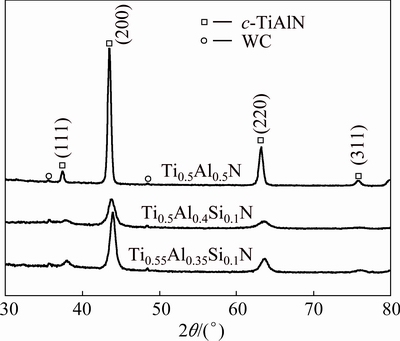
Fig. 1 XRD patterns of TiAlN and TiAlSiN coatings
Table 1 Comparison of TiAlN and TiAlSiN coatings

3 Results
3.1 Microstructures and morphologies of TiAlN and TiAlSiN coatings
Figure 1 presents the XRD patterns of TiAlN and TiAlSiN coatings. All coatings exhibit a single cubic phase of (Ti,Al)N structure. Crystalline HCP-AlN, Si3N4 or titanium silicide phases are not detected. The XRD patterns of Ti0.5Al0.4Si0.1N coating and Ti0.55Al0.35Si0.1N coating indicate the possible existence of amorphous structure. The diffraction peaks of TiAlSiN coatings are found to shift towards higher angles slightly and become broader. Both solid solution effect and internal stress may contribute to the shifting of diffraction peaks [6]. The decreased grain size and increased internal stress may cause peak broadening. The lattice parameter of c-(Ti,Al)N phase, grain size and residual stress of TiAlN and TiAlSiN coatings are compared in Table 1. The lattice parameter of c-(Ti,Al)N phase for TiAlSiN coatings is smaller than that of TiAlN coating. It indicates that TiAlSiN coatings have a solid solution microstructure where Si atoms with smaller radius partially occupy Ti and Al positions in the c-(Ti,Al)N lattice. The dissolution of Si into c-(Ti,Al)N lattice intensifies the lattice distortion. Therefore, TiAlSiN coatings possess higher residual stress than TiAlN coating, which makes the peaks shift toward higher diffraction angles. The addition of Si also results in the grain refinement of TiAlSiN coatings. Compared with Ti0.55Al0.35Si0.1N coating, Ti0.5Al0.4Si0.1N coating exhibits finer grains and higher residual compressive stress. CHEN et al [24] also observed decreased grain size with increasing the Al content in TiAlSiN coatings containing 6% Si.
The XRD patterns of Ti0.5Al0.4Si0.1N coating and Ti0.55Al0.35Si0.1N coating indicate the possible formation of (Ti,Al,Si)N solid solution and amorphous structure. In order to determine the form of Si in the TiAlSiN coatings, chemical bonding state of nitrogen and silicon was analyzed by XPS. There are two peaks in XPS N 1s spectrum of the TiAlSiN coating, as shown in Fig. 2(a). The peak at 396.5 eV corresponds to nitrogen in TiN or AlN [9]. Since the binding energy of TiN and AlN is very similar, it is not easy to distinguish the peaks of TiN and AlN from the spectrum. The peak at 398.3 eV can correspond to the binding energy of Si3N4 [1,9]. The spectrum of Si 2p is shown in Fig. 2(b). This peak is centered at 101.8 eV and it is identified as Si3N4 binding energy [5]. The peaks pertaining to free silicon (99.0 eV) and other silicon compounds are not observed in the spectra, which indicates that silicon exists in the form of Si3N4. As no Si3N4 crystalline peak is observed in the XRD patterns shown in Fig. 1, it can be concluded that Si3N4 phase exists as an amorphous phase. The XRD and XPS results imply that TiAlSiN coatings are composed of nano-sized (Ti,Al,Si)N crystallites and armorphous Si3N4. This is consistent with other Refs. [7,11-13, 16,25,26].
The fractured cross-section morphologies of TiAlN and TiAlSiN coatings are shown in Fig. 3. TiAlN coating shows a pronounced columnar morphology. Although TiAlSiN coatings seem to be columnar morphology, the feature becomes slightly blurred. It is expected that the mechanical properties of TiAlSiN coatings improve due to the reduction in the columnar morphology, because the weak bonding between columns is harmful to the mechanical properties [9].
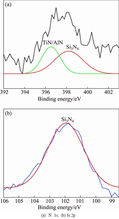
Fig. 2 XPS spectra of Ti0.5Al0.4Si0.1N coating
3.2 Mechanical properties of TiAlN and TiAlSiN coatings
3.2.1 Nano-indentation test
The hardness of TiAlN and TiAlSiN coatings is listed in Table 1. The addition of Si into TiAlN coating increases the hardness of TiAlSiN coatings. Compared with Ti0.55Al0.35Si0.1N coating, Ti0.5Al0.4Si0.1N coating has higher hardness.

Fig. 3 Fractured cross-section morphologies of TiAlN and TiAlSiN coatings
3.2.2 Scratch test
The acoustic emission (AE) and macrographs of scratch of TiAlN and TiAlSiN coatings are shown in Fig. 4. The adhesion strength is determined by the critical load at which continuous high-amplitude AE peak begins to appear, which corresponds to the occurrence of adhesive failure [17,21]. As shown in Table 1, the adhesion strength of Ti0.5Al0.5N coating is 75 N, while those of Ti0.5Al0.4Si0.1N and Ti0.55Al0.35Si0.1N coatings decrease to 39 and 38 N, respectively. Compared with TiAlN coating, TiAlSiN coatings exhibit much lower adhesion strength. Similar phenomenon has been observed in TiAlSiN coatings deposited on the steel or cemented carbide substrates by magnetron sputtering, cathodic arc evaporation, and cathodic vacuum arc ion plating [3,7,8,15,16].
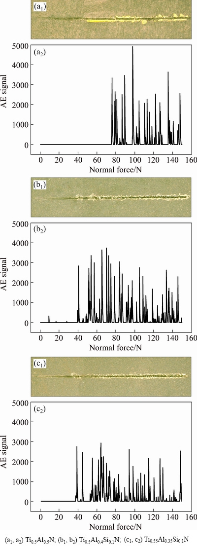
Fig. 4 Macrographs of scratch track (a1, b1, c1) and acoustic emission (a2, b2, c2)
A rough assessment of coating toughness can be made indirectly by analyzing the acoustic emission signal. Compared with Ti0.5Al0.4Si0.1N and Ti0.55Al0.35-Si0.1N coatings, the intensity of acoustic emission signals in Ti0.5Al0.5N coating is higher, and there are more high-amplitude acoustic emission signals, as shown in Fig. 4. It indicates that the toughness of TiAlSiN coatings improves. After the spallation occurring, some low-amplitude acoustic emission signals due to crack formation in scratch track are frequently observed in TiAlSiN coatings. The intensity of low-amplitude acoustic emission signals in Ti0.55Al0.35Si0.1N coating is lower and the amount is less than that of Ti0.5Al0.4Si0.1N coating. It indicates that Ti0.55Al0.35Si0.1N coating is tougher than Ti0.5Al0.4Si0.1N coating.
3.3 Failure modes of TiAlN and TiAlSiN coatings
The improved toughness of TiAlSiN coatings can be further confirmed by the observation of failure modes. The optical micrographs of scratches of TiAlN and TiAlSiN coatings are shown in Fig. 5. Semi-circular spallation propagates outwards from the center line of the scratch track in Ti0.5Al0.5N coating, and the area of exposed substrate often extends beyond the borders of the scratch track. The dominant failure mode in TiAlN coating is wedging spallation, which is a typical brittle failure mode [21,22].
By contrast, TiAlSiN coatings fail by buckling spallation, which is often associated with plastic deformation. The area of exposed substrate is small and mostly confined within scratch borders. Despite of similar failure mode, the spallation in the Ti0.55Al0.35Si0.1N coating is not as severe as that in the Ti0.5Al0.4Si0.1N coating. Accompanied by the reduction of low-amplitude acoustic emission in Ti0.55Al0.35Si0.1N coating, the total amount of cracking in the scratch track decreases. It also indicates that the toughness of Ti0.55Al0.35Si0.1N coating is higher than that of Ti0.5Al0.4Si0.1N coating.
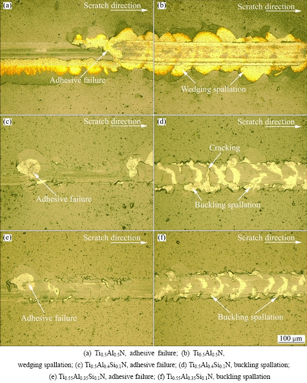
Fig. 5 Optical micrographs of scratch tracks of TiAlN and TiAlSiN coatings
4 Discussion
4.1 Effect of Si addition on mechanical properties of TiAlSiN coatings
When the grain size is less than 10 nm, the most important factor that influences the mechanical properties is the grain boundary sliding ability [27-29]. Our experimental results show that Ti0.5Al0.4Si0.1N and Ti0.55Al0.35Si0.1N coatings have nc-(Ti,Al,Si)N/a-Si3N4 structure (“nc” means nanocrystal and “a” means amorphous). The grain sizes of Ti0.5Al0.4Si0.1N and Ti0.55Al0.35Si0.1N coatings are 10 and 12 nm, respectively. Such a nanocomposite structure, i.e., a randomly oriented nanocrystals embedded within a thin amorphous matrix, provides better coherence at the grain boundaries than purely polycrystalline composites, which hinders grain boundary sliding more effectively and therefore increases the coating hardness [10,13,27,30]. The nano-sized grains also contribute to the increased coating hardness due to the difficulty of dislocation multiplication and movement in nanocrystals [10]. Additionally, the dissolution of Si into c-(Ti,Al)N lattice also leads to increased coating hardness [12]. In summary, the increased hardness in Ti0.5Al0.4Si0.1N and Ti0.55Al0.35Si0.1N coatings is attributed to the grain boundary hardening, grain refinement hardening and solution hardening.
The improved toughness of Ti0.5Al0.4Si0.1N coating and Ti0.55Al0.35Si0.1N coating can also be attributed to the nano-composite structure. The strong interfaces between nanocrystals and amorphous matrix prevent dislocation multiplication or movement and grain boundary sliding. According to Ref. [10], the crystals of a few nanometers size are free of dislocations. The formation of dislocations is possible in such small grains, but dislocation multiplication is difficult. Besides, the thickness of the amorphous tissue is very thin, which is often less than 1 nm at the optimum hardness [3,30-32]. It is difficult for the dislocations to move through the sub-nanometer three-dimensional amorphous skeletons [10,27]. Moreover, the presence of an amorphous phase on the boundaries helps to deflect and terminate cracks [28,33]. Brittle fracture may be eliminated due to the crack termination [33], which is proven by comparing the failure modes of TiAlN coating (wedging spallation) and TiAlSiN coatings (buckling spallation). Therefore, compared with Ti0.5Al0.5N coating, the toughness of Ti0.5Al0.4Si0.1N coating and Ti0.55Al0.35Si0.1N coating improves.
The hardness of Ti0.5Al0.4Si0.1N coating is higher than that of Ti0.55Al0.35Si0.1N coating. In comparison with Ti0.55Al0.35Si0.1N coating, Ti0.5Al0.4Si0.1N coating exhibits small grain size and high residual stress. Finer grains and higher residual compressive stress contribute to higher hardness of Ti0.5Al0.4Si0.1N coating, because in addition to grain boundaries, the defects responsible for the compressive intrinsic stress act as the obstacles for dislocation movement [34].
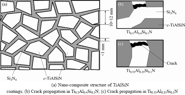
Fig. 6 Schematics of crack propagation in nano-composite structure of TiAlSiN coatings
In the nano-composite structure of TiAlSiN coatings, Si3N4 matrix is the most possible place for the cracks to initiate and propagate [10,28]. CHEN et al [24] suggested that the Al content affects the grain size and a-Si3N4 phase distribution. Because the Si content of Ti0.5Al0.4Si0.1N coating is the same as that of Ti0.55Al0.35Si0.1N coating, it can be assumed that the volume fraction of Si3N4 phase in these two coatings is equal. Compared with Ti0.55Al0.35Si0.1N coating, the nanocrystals in Ti0.5Al0.4Si0.1N coating are finer, and accordingly Si3N4 amorphous tissue surrounding nanocrystals is thinner. As illustrated in Fig. 6, in Ti0.5Al0.4Si0.1N coating, it is easier for the cracks to propagate into the next amorphous tissue because the distance of crack propagation in the Si3N4 becomes shorter and less energy is consumed for crack propagation. Therefore, the inhibition of crack propagation becomes weaker and the toughness of Ti0.5Al0.4Si0.1N is lower than that of Ti0.55Al0.35Si0.1N coating.
The above experimental results show that the addition of 10% Si into TiAlN coatings results in the formation of nc-(Ti,Al,Si)N/a-Si3N4, thus, the hardness and toughness of TiAlSiN coatings increase. However, the adhesion strength of TiAlSiN coatings decreases. The reduced adhesion strength of Ti0.5Al0.4Si0.1N and Ti0.55Al0.35Si0.1N coatings is ascribed to their high residual stress.
4.2 Effect of Si addition on failure modes of TiAlSiN coatings
During scratch test, TiAlN and TiAlSiN coatings exhibit different failure modes, which can be attributed to different coating adhesion and coating properties. Figures 7(a)-(c) show the schematics of different stages of wedging spallation observed in Ti0.5Al0.5N coating. Ti0.5Al0.5N coating shows low toughness, but the adhesion strength between Ti0.5Al0.5N coating and cemented carbide substrate is very high. Thus, it is possible that the interfacial adhesion between Ti0.5Al0.5N coating and cemented carbide substrate is strong relative to the cohesive strength of Ti0.5Al0.5N coating. During the scratch test of TiAlN coating, compressive shear cracking of the coating occurs once the critical load is reached (Fig. 7(a)). Further straining results in differential contraction strains which drive wedges of the adjacent coating layer under the segment bounded by the shear cracks. Then, decohesion at the interface occurs gradually (Fig. 7(c)). Finally, Ti0.5Al0.5N coating fails as a result of wedging spallation.

Fig. 7 Schematics of scratch failure modes for TiAlN and TiAlSiN coatings
The increase of coating toughness can prevent the shear crack propagation. The interfacial crack propagation tends to occur in a ductile manner. Thus, the susceptibility of the coating-substrate system to wedging spallation can be reduced [22]. Compared with TiAlN coating, the toughness of TiAlSiN coatings improves but the adhesion strength between TiAlSiN coating and substrate decreases. When the indenter passes on the TiAlSiN coatings, local interfacial decohesion can lead to the buckling of coatings under the action of compressive stress because the interfacial adhesion of TiAlSiN coatings is relatively poor (Fig. 7(d)). Continued straining may result in increased buckling height. Subsequently, through-thickness cracks propagate in the regions of local tensile stress (Fig. 7(e)). Coating fracture occurs when the crack-like defects within the coatings satisfy the fracture conditions. The coatings then fail by buckling spallation (Fig. 7(f)).
5 Conclusions
1) The addition of Si increases the hardness and toughness of TiAlSiN coatings. Ti0.5Al0.4Si0.1N coating exhibits higher hardness and lower toughness than Ti0.55Al0.35Si0.1N coating. The improved hardness and toughness of TiAlSiN coatings are attributed to the formation of nc-(Ti,Al,Si)N/a-Si3N4 nano-composite structure.
2) Compared with Ti0.5Al0.5N coating, the adhesion strength of Ti0.5Al0.4Si0.1N and Ti0.55Al0.35Si0.1N decreases because of high residual stresses.
3) TiAlN and TiAlSiN coatings exhibit different failure modes in the scratch test. The dominant failure mode of Ti0.5Al0.5N coating is wedging spallation due to low toughness and strong interfacial adhesion. The dominant failure mode of Ti0.5Al0.4Si0.1N and Ti0.55Al0.35Si0.1N coatings is buckling spallation due to improved toughness and weakened interfacial adhesion.
Acknowledgments
The authors would like to thank Jin-long LI, Tao HU, Xiao PENG and Yi-rong YAO for the help during the test. The authors also thank Kennametal Inc. for providing research funding. The authors are grateful for the help provided by PANalytical Division of Spectris Instrumentation & System Shanghai Ltd. and the Instrumental Analysis & Research Center in Shanghai University.
References
[1] VENNEMANN A, STOCK H R, KOHLSCHEEN J, RAMBADT S, ERKENS G. Oxidation resistance of titanium-aluminium-silicon nitride coatings [J]. Surface and Coatings Technology, 2003, 174-175: 408-415.
[2] CARVALHO S, RIBEIRO E, REBOUTA L, TAVARES C, MENDONCA J P, CAETANO MONTEIRO A, CARVALHO N J M, de HOSSON J T M, CAVALEIRO A. Microstructure, mechanical properties and cutting performance of superhard (Ti,Si,Al)N nanocomposite films grown by d.c. reactive magnetron sputtering [J]. Surface and Coatings Technology, 2004, 177-178(1): 459-468.
[3] DERFLINGER V H,  A, Ante M. Mechanical and structural properties of various alloyed TiAlN-based hard coatings [J]. Surface and Coatings Technology, 2006, 200(16-17): 4693-4700.
[4] Flink A, Andersson J M, Alling B, Daniel R,  J, Karlsson L, Hultman L. Structure and thermal stability of arc evaporated (Ti0.33Al0.67)1-xSixN thin films [J]. Thin Solid Films, 2008, 517(2): 714-721.
[5] Carvalho S, Rebouta L, Ribeiro E, Vaz F, Tavares C J, Alves E, Barradas N P, Riviere J P. Structural evolution of Ti-Al-Si-N nanocomposite coatings [J]. Vacuum, 2009, 83(10): 1206-1212.
[6] Pfeiler M, Zechner J, Penoy M, Michotte C, Mitterer C, Kathrein M. Improved oxidation resistance of TiAlN coatings by doping with Si or B [J]. Surface and Coatings Technology, 2009, 203(20-21): 3104-3110.
[7] Yu Dong-hai, Wang Cheng-yong, Cheng Xiao-ling, ZHANG Feng-lin. Microstructure and properties of TiAlSiN coatings prepared by hybrid PVD technology [J]. Thin Solid Films, 2009, 517(17): 4950-4955.
[8] CHEN L, WANG S Q, DU Y, ZHOU S Z, GANG T, FEN J C, CHANG K K, LI Y W, XIONG X. Machining performance of Ti-Al-Si-N coated inserts [J]. Surface and Coatings Technology, 2010, 205(2): 582-586.
[9] Barshilia H C, Ghosh M, Ramakrishna S R, Rajam K S. Deposition and characterization of TiAlSiN nanocomposite coatings prepared by reactive pulsed direct current unbalanced magnetron sputtering [J]. Applied Surface Science, 2010, 256(21): 6420-6426.
[10]  S, Reiprich S, Shizhi L. Superhard nanocrystalline composite materials: The TiN/Si3N4 system [J]. Applied Physics Letters, 1995, 66(20): 2640-2645.
[11] Park I W, Choi S R, Lee M H, Kim K H. Effects of Si addition on the microstructural evolution and hardness of Ti-Al-Si-N films prepared by the hybrid system of arc ion plating and sputtering techniques [J]. Journal of Vacuum Science and Technology A, 2003, 21(4): 895-899.
[12] Park I W, Choi S R, Suh J H, Park C G, Kim K H. Deposition and mechanical evaluation of superhard Ti-Al-Si-N nanocomposite films by a hybrid coating system [J]. Thin Solid Films, 2004, 447-448(1): 443-448.
[13] S, Veprek-Heijman M G J, Karvankova P, Prochazka J. Different approaches to superhard coatings and nanocomposites [J]. Thin Solid Films, 2005, 476(1): 1-29.
[14] Kang M C, Kim M W, Kim K R, Kim K H, Jung S Y, Kim C, Ahn D G. Adhesion property and tool wear of hybrid deposited Ti0.67Al0.23Si0.09N coatings with WC grain size and Co content [J]. Journal of Computational and Theoretical Nanoscience, 2008, 5(8): 1772-1776.
[15] Philippon D, Godinho V, Nagy P M, Delplancke- Ogletree M P, Fernández A. Endurance of TiAlSiN coatings: Effect of Si and bias on wear and adhesion [J]. Wear, 2011, 270(7-8): 541-549.
[16] SHI J, PEI Z L, GONG J, SUN C, MUDERS C M, JIANG X. Effect of Si content on the microstructure and mechanical properties of Ti-Al-Si-N films deposited by cathodic vaccum arc ion plating [J]. Acta Metallurgica Sinica, 2012, 48(11): 1349-1356.
[17] ZHANG Shi-hong, CAI Fei, LI Ming-xi. The nanostructured phase transition and thermal stability of superhard f-TiN/h-AlSiN films [J]. Surface and Coatings Technology, 2012, 206(17): 3572-3579.
[18]  L A, PAKULA D, Hajduczek E. Structure and properties of the multi-component TiAlSiN coatings obtained in the PVD process in the nitride tool ceramics [J]. Journal of Materials Processing Technology, 2004, 157-158: 331-340.
[19] Kim S K, Vinh P V, Kim J H, Ngoc T. Deposition of superhard TiAlSiN thin films by cathodic arc plasma deposition [J]. Surface and Coatings Technology, 2005, 200(5-6): 1391-1394.
[20]  L A, Golombek K. Structure and properties of selected cemented carbides and cermets covered with TiN/(Ti,Al,Si)N/TiN coatings obtained by the cathodic arc evaporation process [J]. Materials Research, 2005, 8(2): 113-116.
[21] Bull S J. Failure modes in scratch adhesion testing [J]. Surface and Coatings Technology, 1991, 50(1): 25-32.
[22] Bull S J. Failure mode maps in the thin film scratch adhesion test [J]. Tribology International, 1997, 30(7): 491-498.
[23] PalDey S, Deevi S C. Single layer and multilayer wear resistant coatings of (Ti,Al)N: A review [J]. Materials Science Engineering A, 2003, 342(1-2): 58-79.
[24] CHEN L, DU Y, WANG A J, WANG S Q, ZHOU S Z. Effect of Al content on microstructure and mechanical properties of Ti-Al-Si-N nanocomposite coatings [J]. International Journal of Refractory Metals and Hard Materials, 2009, 27(4): 718-721.
[25] Carvalho S, Ribeiro E, Rebouta L, Pacaud J, Goudeau P, Renault P O, Rivière J P, Tavares C J. PVD grown (Ti,Si,Al)N nanocomposite coatings and (Ti,Al)N/(Ti,Si)N multilayers: Structural and mechanical properties [J]. Surface and Coatings Technology, 2003, 172(2-3): 109-116.
[26] XIE Z W, WANG L P, WANG X F, HUANG L, LU Y, YAN J C. Influence of oxidation on the structural and mechanical properties of TiAlSiN coatings synthesized by multi-plasma immersion ion implantation and deposition [J]. Nuclear Instruments and Methods in Physical Research Section B, 2012, 271(1): 1-5.
[27]  M,
M,  M. Recent progress in the superhard nanocrystalline composites: Towards their industrialization and understanding of the origin of the superhardness [J]. Surface and Coatings Technology, 1998, 108-109(1-3): 138-147.
[28] ZHANG Sam, SUN Deen, FU Yong-qing, DU He-jun. Recent advances of superhard nanocomposite coatings: A review [J]. Surface and Coatings Technology, 2003, 167(2-3): 113-119.
[29] Rafaja D, Poklad A, Klemm V, Schreiber G, Heger D,  M. Microstructure and hardness of nanocrystalline Ti1-x-yAlxSiyN thin films [J]. Materials Science Engineering A, 2007, 462(1-2): 279-282.
[30]  S, Peiprich S. A concept for the design of novel superhard coatings [J]. Thin Solid Films 1995, 268(1-2): 64-71.
[31] Patscheider J, Zehnder T, Diserens M. Structure- performance relations in nanocomposite coatings [J]. Surface and Coatings Technology, 2001, 146-147(9-10): 201-208.
[32] Godinho V, Rojas T C, Trasobares S, Ferrer F J, Delplancke-Ogletree M P, Fernández A. Microstructural and chemical characterization of nanostructured TiAlSiN coatings with nanoscale resolution [J]. Microscopy Microanalysis, 2012, 18(3): 568-581.
[33] Voevodin A A, Zabinski J S. Supertough wear-resistant coatings with ‘chameleon’ surface adaptation [J]. Thin Solid Films, 2000, 370(1-2): 223-231.
[34] Raveh A, Zukerman I, Shneck R, Avni R, Fried I. Thermal stability of nanostructured superhard coatings: A review [J]. Surface and Coatings Technology, 2007, 201(13): 6136-6142.
朱丽慧1,宋 诚1,倪旺阳2,3,刘一雄2
1. 上海大学 材料科学与工程学院,上海 200072;
2. Kennametal Inc., 1600 Technology Way, Latrobe, PA 15650, USA;
3. Stryker Orthopaedics, 325 Corporate Drive, Mahwah, NJ 07430, USA
摘 要:研究加入10% Si(摩尔分数)对TiAlSiN涂层的影响。采用阴极电弧蒸镀在WC-Co基体上沉积Ti0.5Al0.5N、 Ti0.5Al0.4Si0.1N和 Ti0.55Al0.35Si0.1N涂层,通过X射线衍射(XRD)、 X射线光电子能谱(XPS)、扫描电镜(SEM)、纳米压痕测量和划痕试验研究涂层的显微组织和力学性能,探讨Si对涂层的性能和结合失效模式的影响机理。结果表明:加入10% Si后,涂层中形成非晶Si3N4包覆(Ti,Al,Si)N纳米晶的纳米复合结构。TiAlSiN涂层的硬度和韧性升高,但结合强度下降。与Ti0.55Al0.35Si0.1N涂层相比, Ti0.5Al0.4Si0.1N涂层的硬度较高但韧性较低。TiAlN涂层由于韧性低、界面结合强,因此结合失效模式以楔形剥落为主。TiAlSiN 涂层由于韧性改善、但界面结合变差,因此结合失效模式以屈曲剥落为主。
关键词:TiAlSiN涂层;TiAlN涂层;阴极电弧蒸镀;结合强度
(Edited by Mu-lan QIN)
Corresponding author: Li-hui ZHU; Tel: +86-21-56331462; Fax: +86-21-56331466; E-mail: lhzhu@i.shu.edu.cn
DOI: 10.1016/S1003-6326(16)64273-5

