Dynamic modelling and properties analysis of 3RSR parallel mechanism considering spherical joint clearance and wear
��Դ�ڿ������ϴ�ѧѧ��(Ӣ�İ�)2021���3��
�������ߣ������� ������ ������
����ҳ�룺712 - 727
Key words��parallel mechanism; dynamics; spherical joint clearance; wear; Newton-Euler method
Abstract: The collision and wear caused by inevitable clearance in kinematic pair have an effect on the dynamic characteristics of the mechanism. Therefore, we established the dynamic model of a 3RSR (R is the revolute joint and S is the spherical joint) parallel mechanism with spherical joint clearance based on the modified Flores contact force model and the modified Coulomb friction model using Newton-Euler method. The standard quaternion was introduced in the constraint equation, and the four-order Runge-Kutta method was adopted to solve the 3RSR dynamic model. The simulation results were compared and analyzed with the numerical results. The geometrical parameters of the worn ball socket were solved based on the Archard wear model, and the geometrical reconstruction of the worn surface was carried out. The geometric reconstruction parameters were substituted into the dynamic model, which was to analyze the dynamic response of the 3RSR parallel mechanism with wear and spherical joint clearance. The simulation results show that the irregular wear occurs in the spherical joint with clearance under the presence of the impact and friction force. The long-term wear will increase the fluctuation of the contact force, thereby decreasing the movement stability of the mechanism.
Cite this article as: HOU Yu-lei, DENG Yun-jiao, ZENG Da-xing. Dynamic modelling and properties analysis of 3RSR parallel mechanism considering spherical joint clearance and wear [J]. Journal of Central South University, 2021, 28(3): 712-727. DOI: https://doi.org/10.1007/s11771-021-4640-y.

J. Cent. South Univ. (2021) 28: 712-727
DOI: https://doi.org/10.1007/s11771-021-4640-y

HOU Yu-lei(������)1, DENG Yun-jiao(������)1, ZENG Da-xing(������)2
1. School of Mechanical Engineering, Yanshan University, Qinhuangdao 066004, China;
2. School of Mechanical Engineering, Dongguan University of Technology, Dongguan 523015, China
 Central South University Press and Springer-Verlag GmbH Germany, part of Springer Nature 2021
Abstract: The collision and wear caused by inevitable clearance in kinematic pair have an effect on the dynamic characteristics of the mechanism. Therefore, we established the dynamic model of a 3RSR (R is the revolute joint and S is the spherical joint) parallel mechanism with spherical joint clearance based on the modified Flores contact force model and the modified Coulomb friction model using Newton-Euler method. The standard quaternion was introduced in the constraint equation, and the four-order Runge-Kutta method was adopted to solve the 3RSR dynamic model. The simulation results were compared and analyzed with the numerical results. The geometrical parameters of the worn ball socket were solved based on the Archard wear model, and the geometrical reconstruction of the worn surface was carried out. The geometric reconstruction parameters were substituted into the dynamic model, which was to analyze the dynamic response of the 3RSR parallel mechanism with wear and spherical joint clearance. The simulation results show that the irregular wear occurs in the spherical joint with clearance under the presence of the impact and friction force. The long-term wear will increase the fluctuation of the contact force, thereby decreasing the movement stability of the mechanism.
Key words: parallel mechanism; dynamics; spherical joint clearance; wear; Newton-Euler method
Cite this article as: HOU Yu-lei, DENG Yun-jiao, ZENG Da-xing. Dynamic modelling and properties analysis of 3RSR parallel mechanism considering spherical joint clearance and wear [J]. Journal of Central South University, 2021, 28(3): 712-727. DOI: https://doi.org/10.1007/s11771-021-4640-y.
1 Introduction
The clearance between the movement hinge components in a mechanism is ineluctable in the actual condition. The result of the clearance was affected by many aspects, from design, manufacturing and application, such as machining and manufacturing, installation and commissioning, deformation of the material, friction and wear between the two adjacent components [1, 2]. The existence of the clearance, to a large extent, will cause vibration and noise of a mechanism, resulting in excessive wear between components, thereby decreasing the accuracy and the lifespan of the mechanism.
In recent years, a mechanism including movement hinges with clearance has been studied by many scholars. BAI et al [3] took a slider-crank mechanism as an example and proposed a new hybrid contact force model. It was embedded that the non-linear stiffness coefficient of an ameliorative elastic model on the basis of the contact stiffness of a Lankarani-Nikravesh contact force model. ZHANG et al [4] established a dynamic model of a planar 3RRR parallel mechanism including multiple revolute clearance joints. They analyzed the effects of loads, drive velocities and motion trajectories on the performance of the mechanism. WANG et al [5] proposed an improved contact force model though modifying the stiffness coefficient in the Flores contact force model from a constant one to a non-linear one. Then they established a dynamic model of a 4-SPS/CU (S represents a spherical joint; P represents a prismatic joint; C represents a cylindrical joint; U represents a hooke joint) parallel mechanism including spherical joints with clearance using the augmented method. Subsequently, they estimated the normal and tangential contact forces between ball and socket based on the improved Lankarani-Nikravesh contact force model and a modified Coulomb friction model, respectively [6-8]. In addition, they calculated the contact pressure between contact bodies by the improved contact force model and approximate contact area [9]. VAREDI-KOULAEI et al [10] took a 3RRR (R represents a revolute joint) planar parallel manipulator as the research object, and a continuous contact force model, based on the elastic Hertz theory together with a dissipative term, was used to evaluate the contact forces. 30 different contact force models for general (point) and cylindrical (line) contacts are compared by SKRINJAR et al [11]. The numerical modeling analysis and experimental investigation of a slider-crank mechanism containing revolute clearance joints were carried out by FLORES et al [12]. Its feasibility was verified to some extent by comparing the theoretical analysis with the experimental data. It was selected as a model mechanism that a 3D slider-crank mechanism considering the influence of the clearances and flexibility in spherical joints on the mechanism vibration, and a set of different clearance values, a multi-axes flexible connection with cylindrical cross section and driving speeds were considered in the experimental investigations by ERKAYA [13]. The spherical joint was usually applied in the spatial parallel mechanism, which can refer to the review about the spherical clearance joints including friction [14]. AMBROSIO et al [15] proposed a formulation in which both perfect and clearance/bushing joints share the same kinematic information making their modelling data similar.
During the working process of a mechanism, the long-term wear between the two adjacent components, caused by collision and friction, will produce many irregular pits on the contact surface, thereby changing the dynamic characteristics of the mechanism. The dynamic wear characteristics of a revolute joint with clearance were analyzed by BAI et al [2]. MUKRAS et al [16] took a slider-crank mechanism as an example to study the wear characteristics of the mechanism with clearance. In their study, a wear model with the perpetually changing clearance as the real wear was substituted into the dynamic model of the system. Moreover, the wear prediction data were compared with their experimental data to verify the correctness of the new model. FLORES [17] established a numerical wear model of a four-bar mechanism based on the multi-body system equation and the Archard��s wear model, and obtained the results that could depict the uneven wear of the joint surface under different contact areas and different collision frequencies between the two adjacent joints. Considering the influences of pressure and temperature on the wear loss of hinge, JIANG et al [18] established a wear model of a hinge mechanism. The wear state of the hinge with friction in the slider-crank mechanism was studied using the numerical simulation method. ASKARI et al [19] studied the dynamics modelling and analyzed the wear in a spatial hip mechanism including spherical joints clearance. MARQUES et al [20] detailedly analyzed the role of friction modelling in the dynamic response of multibody system. We can observe that most of the wear-related researches above mentioned were aimed at the planar linkage mechanisms. In addition, the computation theory of wear for space parallel mechanisms still needs to be further well studied.
The publications related to the dynamic analysis of a mechanism including the revolute joint clearance were relatively common. However, the studies on a parallel mechanism including the spherical joint clearance were less. The studies on the wear characteristics of a parallel mechanism with the spherical joint clearance have few been reported [5].
In this study, a 3RSR parallel mechanism including the spherical joints clearance was used to investigate the effect of the wear in spherical joints on the dynamic response of the mechanism. We established a dynamic model of a 3RSR parallel mechanism and analyzed its dynamic response by solving the dynamic model. In addition, the wear loss of a spherical joint with clearance, based on the Archard��s wear model, was solved. Furthermore, the contact force on the spherical joints and the acceleration of the moving platform in the 3RSR parallel mechanism were solved and analyzed.
The contributions of this paper are fourfold. First, based on modified Flores contact force and Coulomb friction model, the dynamic model of 3RSR parallel mechanism with spherical joint clearance is established. Second, the Archard is embedded into dynamic model with clearance to get the dynamic model considering clearance and wear. Third, comparing the results of dynamic model between spherical joint with clearance and ideal kinematic pair, the correctness of the modelling and solution is verified. Fourth, the dynamic response of 3RSR parallel mechanism with wear properties and spherical joint clearance is analyzed.
The remainder of this paper is organized as follows. Section 2 describes the process of dynamic modelling of a 3RSR parallel mechanism under considering the spherical joint clearance. Section 3 introduces the modified Coulomb friction into the contact force model. Section 4 introduces the Archard��s wear model. Section 5 presents some dynamic numerical simulations. In Section 6, some concluding comments are provided.
2 Dynamic modelling of 3RSR parallel mechanism with spherical joint clearance
The structural composition of 3RSR parallel mechanism is shown in Figure 1. It comprises a fixed platform, a moving platform and three identical branches which is connected between the two platforms. The three drive rods connected with the fixed platform are numbered as 1, 2 and 3, respectively. The three transmission rods connected with the moving platform are numbered as 4, 5 and 6, respectively. The moving platform is numbered as 7. Using the revolute joints, the drive rods numbered as 1, 2 and 3 are connected with the points, A1, A2 and A3, respectively, of the fixed platform. In the same way, using the revolute joints, the transmission rods numbered as 4, 5 and 6 are connected with the points B1, B2 and B3 of the moving platform, respectively. Similarly, using the spherical joints numbered as S1, S2 and S3, the drive rods numbered as 1, 2 and 3 are connected with the transmission rods numbered as 4, 5 and 6, respectively. The fixed coordinate system O-xyz is fixed on the mass center of the fixed platform, where the x axis points to the hinge point A1; the z axis is perpendicular to the plane of the fixed platform and upwards; and the y axis is determined by the x axis and the z axis through the right-hand rule. As shown in Figure 1, the local coordinate systems Oi-xiyizi (i=1, 2, ��, 6) are fixed on their corresponding rods, respectively, and their coordinate origins are located at the mass center of each rod. The moving coordinate system O7-x7y7z7 is fixed on the moving platform. Its coordinate origin, O7, is located at the mass center of the moving platform. The x7 axis points to the hinge point B1, and the z7 axis is perpendicular to the plane of the moving platform and upwards, and the y7 axis is determined by the x7 axis and the z7 axis using the right-hand rule.
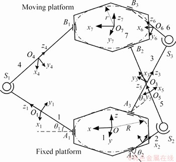
Figure 1 Schematic of 3RSR parallel mechanism
We assume that there is a clearance at the spherical joint S1, and then, the motion equation of the spatial multibody system, according to its constraint relation, is established [21].
To describe the kinematic state of the mechanism accurately, the coordinate of the mass center and the standard quaternion of each movement component are selected to represent its position and the orientation. The coordinate of mass center and the standard quaternion of each component are taken as the generalized coordinate, which is expressed as follows:
 (1)
(1)
where
 is the coordinate of local coordinate origin located on component k in the fixed coordinate system;
  is the standard quaternion of the local coordinate system of the component k in the fixed coordinate system, k=1, 2, ��, 7.
In the fixed coordinate system O-xyz, the attitude transformation matrix of the local coordinate system located on the component k, is expressed by the standard quaternion as:
 (2)
(2)
where k=1, 2, ��, 7.
The standard quaternion satisfied the following relation:
 k=1, 2, ��, 7 (3)
The constraint equation of each spherical joint in the 3RSR parallel mechanism is expressed as follows:
 (4)
(4)
where a and b represent the components connected by the spherical joints, respectively; ra and rb represent the position coordinate vector of the mass center of the components a and b, respectively;  and
and  represent the position vector of the spherical joint center P located in local coordinate systems of the components a and b, respectively.
According to the constraint relation of Eq. (4), the constraint equations of the spherical joints S1, S2 and S3 are expressed as 
 and
and  respectively.
The constraint structure of the revolute joint is shown in Figure 2. The revolute joint was connected between two components, a and b, and its center is the point P.  and
and  stand for the local coordinate systems of the components a and b, respectively. and are the position vectors of the revolute joints center P in the two local coordinate systems, respectively. Qa and Qb are fixed onto components a and b, respectively. In addition, both of them are on the axis of the revolute joints. sa and sb are the vectors of Qa and Qb relative to the revolute joints center P, respectively. Thus, the constraint equation of the revolute joints is expressed as:
 (5)
(5)
According to the constraint relation shown in Eq. (5), the constraint equations of the three points, A1, A2, A3, where the fixed platform are connected with the revolute joints and similarly the other three points on the moving platform, B1, B2, B3, in turn are expressed as


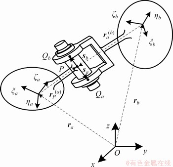
Figure 2 Composition of constrained structure of revolute joint
In addition, there are three driving constraint equations, which is expressed as:
 k=1, 2, 3 (6)
where lk is the length of kth drive rod; ��k is the drive angle of kth drive rod, as shown in Figure 1.
The constraint equation of the ideal kinematic pairs namely, without clearance between the adjacent components, and the driving ones in the 3RSR parallel mechanism are given by Eqs. (3)-(6) as:

 (7)
(7)
Since the clearance existed in the spherical joint S1, the corresponding kinematic constraint  was replaced by the contact force constraint. Therefore, the kinematic constraint equation with the spherical joint clearance becomes:

 (8)
(8)
Then, the velocity constraint equation (Eq. (9)) is obtained by taking the derivative of Eq. (8) versus time:
 (9)
(9)
where  represents the Jacobian matrix of the constraint equation, namely
 is the generalized velocity vector; v is the right-hand side expression of the velocity constraint equation;
  represents the derivative of the constraint equation versus time, namely
The acceleration constraint equation (Eq. (10)) is acquired by taking the second derivative of Eq. (8) versus time
 (10)
(10)
where  is the generalized acceleration vector; �� is the right-hand side expression of the acceleration constraint equation.
Then, using the Newton-Euler method, the dynamic equation of the system with the Lagrange multiplier is established, which was given as follows:
 (11)
(11)
where M is the mass matrix of the system; �� is the Lagrange multiplier vector, which is related to the internal forces and the moment of internal forces between the components connected with the kinematic pair; Q is the generalized force vector including the external forces and the moment of external forces.
A differential algebraic equation is formed by Eqs. (10) and (11), as follows:
 (12)
(12)
and �� are obtained by solving Eq. (12). However, the displacement and the velocity constraint equations of the system were not considered in Eq. (12). Therefore, the constraint breach stability method [22], which was proposed by Baumgarte, is used to compensate the deficiency of Eq. (12). The resulting equation is given as follows:
 (13)
(13)
where  �� and �� are the modified coefficients, which are greater than 0, and
3 Contact force model of 3RSR parallel mechanism with spherical joint clearance
The model of a 3RSR parallel mechanism with spherical joint clearance is shown in Figure 3. In Figure 3, Oi and Oj are the origins of the local coordinate systems; Si and Sj are the center points of the ball head and the ball socket, respectively; Qi and Qj are the collision points on the ball head and the ball socket, respectively;  and
and  are the position vectors of the centers of the ball head and the ball socket in the fixed coordinate system, respectively; n and t are the normal vector and the tangential vector of the contact surface, respectively. Therefore, the clearance vector between the ball head and the ball socket is:
 (14)
(14)
Its unit vector is:
 (15)
(15)
where e is the amplitude of clearance vector, and 
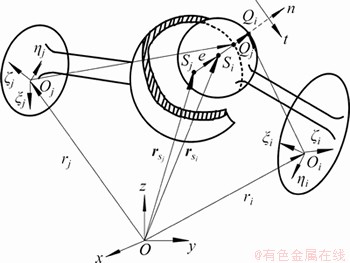
Figure 3 Schematic of spherical joint clearance of 3RSR parallel mechanism
Similarly, t is also a unit vector, and its direction is perpendicular to n and is related to the moving direction of the ball head relative to the ball socket.
The penetration depth of the ball socket is:
 (16)
(16)
where c is the clearance radius namely c=Ri-Rj, in which Ri and Rj are the radii of the ball head and the ball socket, respectively. When �� is positive, the bearing is in contact with the shaft, on the contrary, the bearing is separated from the shaft.
When the collision occurs, the position vectors of the corresponding collision points between the ball head and the ball socket, in the fixed coordinates, are expressed as:
 (17)
(17)
Both sides of Eq. (18) are taken the derivative of time, and then, the velocity vectors of the collision points, in the global coordinate system, are given as follows:
 (18)
(18)
According to Eq. (18), the relative velocity components of the collision points between the ball head and the ball socket, on the normal and tangential directions, are written as:
 (19)
(19)
Considering the collision force could be generated in the process of collision between the ball head and the ball socket, the collision force in our numerical simulation model is calculated. The widely used model for solving the collision force was the Lankarani-Nikravesh contact force model [23, 24]. Although the elastic deformation of the collision process was included and the influence of the damping force was considered in the Lankarani-Nikravesh contact force model, the restitution coefficient limited the application of this model [2-5]. Therefore, in this study, to solve the contact force of the 3RSR parallel mechanism with clearance, the Flores contact force model which is not restricted by the restitution coefficient [5] is used. The expression of the normal contact force between the ball head and the ball socket is represented by the Flores contact force model as:
 (20)
(20)
where K is the stiffness coefficient, which is related to the geometry and the physical properties of the contact surfaces; ce is the restitution coefficient, which is related to the material properties; n is the constant with a value of 1 for metal surfaces;  is the penetration depth;
  is the relative penetration velocity;
  is the initial collision velocity.
Considering the change of the contact area and the stiffness coefficients, which is caused by the geometric deformation during the collision process, the expression of the stiffness coefficient [5], in this study, is as follows:
 (21)
(21)
where Rs=Rj is the radius of the ball socket; ��R=c is the clearance size; E* is the synthetical elastic modulus, which is solved by 
 ��i and ��j are the Poisson ratios of the ball head and the ball socket, respectively; Ei and Ej are the elastic modulus of the ball head and the ball socket, respectively.
The modified Coulomb friction rule proposed by AMBROSIO [25] could prevent the sudden change of the tangential contact force direction. Therefore, in order to enhance the stability of the numerical integration, the modified Coulomb friction rule is adopted to solve the tangential contact force. The expression of the tangential contact force of the ball head on the ball socket is:
 (22)
(22)
where cf is the friction coefficient; vt is the relative tangential velocity of collision; cd is the coefficient of dynamic correction, which is defined as:
 (23)
(23)
where v0 and v1 are the given tolerance velocities, respectively.
The collision force of the ball head on the bearing is expressed as:
 (24)
(24)
4 Wear model of 3RSR parallel mechanism
In a 3RSR parallel mechanism, the collision and friction between the components of the spherical joint with clearance will lead to wear, thereby changing the dynamic characteristics of the mechanism. Therefore, to study the effect of wear on the dynamic performance of the mechanism, the wear model is substituted into the dynamic model of the 3RSR mechanism with spherical joint clearance. Furthermore, to solve the wear loss of the spherical joint with clearance, the Archard��s wear model [2, 17, 26] is used in this study. The expression of the Archard wear model is:
 (25)
(25)
where V is the volume of the wear; s is the distance of the relative slip; Fn is the normal collision force; �� is the wear coefficient, which can be obtained by the material of kinematic pair and wear conditions and �� is a constant; H is the Brinell hardness of the softest material.
However, due to the collision between components of spherical joint, the contact force and the slip distance is discontinuity. Therefore, to solve the wear loss, Eq. (25) is discretized. The discretized expression of Eq. (25) is:
 (26)
(26)
where ��V�� is the wear loss in the ��th time integration step; ��s�� is the slip distance in the ��th time integration step. The time integration step is used to solve numerically the dynamic equation.
The distance of the slip ��s�� is expressed as:
 (27)
(27)
where v�� is the tangential component of the relative velocity between the ball head and the ball socket at collision point; dt represents a time integration step.
In order to analyze the effect of wear of the spherical joint with clearance on the dynamic response [27] of the mechanism, the collision surface is divided and the wear loss of each collision is accumulated according to the wear location, and then, the geometric parameters of the ball socket with wear is obtained. Furthermore, the dynamic response of the 3RSR parallel mechanism with clearance is solved by substituting the obtained geometric parameters to the dynamic equation (Eq. (13)).
Meanwhile, to accurately describe the wear position on the ball socket, the local coordinate system o-xyz whose direction is in line with the local coordinate system o1-x1y1z1 on the drive rod 1 is established. The origin of o-xyz is at the center S1 of the ball socket. The coordinate of the collision point on the ball socket in the o-xyz coordinate system is transformed into the spherical coordinate system, as shown in Figure 4. In Figure 4, there is a direction vector from the origin o in the local coordinate system to the collision point Q. �� represents the angle between the projection of the direction vector in the xoy plane and the forward direction of the x axis (�� is negative when the collision point Q is located on the negative y axis). In addition, there is another direction vector from the origin to the collision point M, and �� represents the angle between the direction vector and the xoy plane (�� is negative when the collision point M is located on the negative z axis).
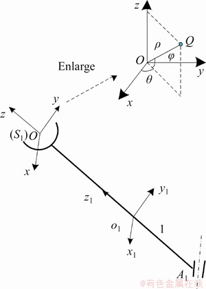
Figure 4 Local coordinate system of spherical joint with clearance
The relationship between the parameters in spherical coordinate system and the Cartesian coordinate system is as follows:

 (28)
(28)
Then, the sphere of the ball socket is divided into the n1��n2 spherical grids with a space of 2��/n1 and ��/n2 along the �� and �� directions, respectively, as depicted in Figure 5. The geometric center point M' of each element was selected as the marker point of the corresponding element. Therefore, the location of each wear element could be determined by recording the azimuth coordinates of the M' points. We assumed that the wear depth at each collision point was same in the one element. Then the wear loss in each element could be summed and accumulated during the simulation, which is express as:
 (29)
(29)
where VN is the summed wear loss at N collision points in the element.
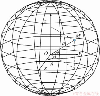
Figure 5 Discrete sketch map of spherical element
It is assumed that the wear depth of each element is uniform. Then the wear depth of each element is obtained by dividing the wear loss by the area of the element:
 (30)
(30)
where h is the wear depth in the element; S is the area of the element.
Once the wear exists in one element, the curvature radius of the element is calculated by summing the ball socket radius and the wear depth of the element, which is:
 (31)
(31)
First, it was taken out that the azimuth coordinate of the marked point M' in each element, and then it was calculated that the curvature radius �� of the corresponding element. Next, the two parameters are selected as the geometric parameters of the ball socket with wear to be used for the geometric surface reconstruction of the ball socket and the dynamic analysis of the mechanism including spherical clearance joints under wear condition.
5 Dynamic numerical simulation of 3RSR parallel mechanism with clearance
5.1 Dynamic numerical analysis of 3RSR parallel mechanism with clearance
When the dynamic simulation model considering the clearance between the ball head and the ball socket is solved, there will be two status, collision status and non-collision status. Therefore, it is very important to detect accurately the collision point when the initial collision velocity and the direction of the collision surface, in each collision, was analyzed. The condition of the collision between the ball head and the ball socket is:
 (32)
(32)
There is at least one collision between tn and tn+1.
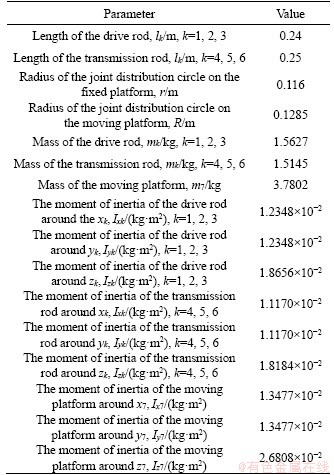
The three-dimensional structure model of a 3RSR parallel mechanism is established, and the material is set to be 45 steel. The basic parameters of the parallel mechanism are calculated using the software and listed in Table 1.
We assume the motion rule of a 3RSR parallel mechanism is as follows:
 (33)
(33)
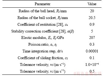
The dynamic simulation parameters of a 3RSR parallel mechanism are listed in Table 2.
Table 1 Basic parameters of 3RSR parallel mechanism
The solution flow is drawn according to the iterative process of a 3RSR parallel mechanism with clearance and shown in Figure 6.
According to the flow chart (Figure 6), the codes are used to solve. Besides, the dynamic model of a 3RSR mechanism including the ideal kinematic pairs, namely spherical joints without clearance, was established, as shown in Figure 7.
The dynamic response of a 3RSR parallel mechanism without clearance was solved by Adams. Then, the contact force could be obtained through comparing the dynamic responses of mechanism including spherical joint with and without clearance. The contact force as a function of time was plotted and shown in Figure 8. The acceleration of the moving platform vs simulation time was obtained, as shown in Figure 9.
Table 2 Dynamic simulation parameters of a 3RSR parallel mechanism
In Figure 8, we can observe that the variation trends of the contact force for spherical joint with and without clearance conditions are basically the same, indicating that the dynamic modeling and its solution are reasonable to some extent. Besides, it is found that the contact force curves of the spherical joint without clearance are smooth, while larger high frequency oscillations are observed in the contact force curves of the mechanism with clearance. In Figure 8(a), the maximum deviation value of the contact forces between with and without clearance conditions is 78.20 N in the x direction, which appears as the time is 3.33 s. Similarly, in Figure 8(b), the maximum deviation value is 53.61 N in the y direction, which corresponds to 2.335 s. In Figure 8(c), the maximum deviation value is 88.02 N at 3.33 s in the z direction. The phenomenon indicates that the presence of the clearance causes the mechanism to be shocked, thereby affecting the continuity of force transmission.
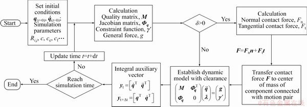
Figure 6 Flow-process diagram of dynamics numerical solution for 3RSR parallel mechanism with clearance
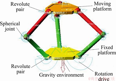
Figure 7 Established dynamic model of 3RSR parallel mechanism
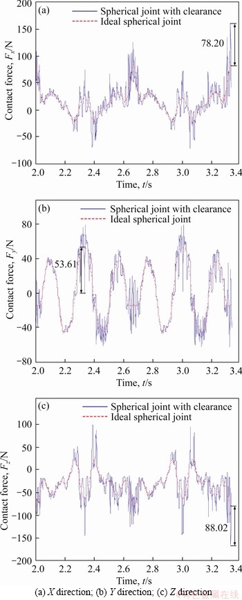
Figure 8 Change of contact force on spherical joint in 3RSR parallel mechanism with contact force in different directions:
As shown in Figure 9, the maximum acceleration deviation values of the moving platform between the mechanisms with and without clearance are 14.59, 11.29 and 14.09 m2/s in the x, y and z directions, respectively, indicating that the fluctuation range of the acceleration caused by the clearance is relatively large. In addition, we can observe that the sudden changes of the acceleration mostly correspond to the inflection point of the acceleration curves through combing Figures 9(a)-(c). Therefore, it is helpful for improving the working stability of the mechanism to reasonably and timely control the movement state of the mechanism.
5.2 Wear properties analysis of 3RSR mechanism
In order to analyze the dynamic wear properties of the mechanism, we set the dimensionless wear coefficient �� and the material hardness H to be 1.736��10-4 and 2.17��109 Pa [2], respectively, based on the established dynamics model with the wear. Figure 10 shows the cumulative wear loss versus the change of the drive rod angle for the 10-cycle (the position of the drive rod runs 10 times from 45�� to 75��), 20-cycle, 30-cycle and 40-cycle simulation of the mechanism with spherical joint clearance. As shown in Figure 10, the wear loss cumulatively increases with an increase in the running cycle. Moreover, the change trends of the wear curves are basically similar with the change of the drive rod angle under different running cycles, suggesting that there is regularity for the wear loss at the position with clearance in the overall change.
Considering the fact that wear is a change of long-term cumulative and its accumulation in the short term is very small, we can only obtain the geometry characteristics of spherical joint with clearance when the simulation time is long enough. To obtain a realistic wear loss, tens of thousands and more cycles numerical simulation should be carried out, making the dynamic simulation a computer intensive and time-consuming method. To reduce the calculation efforts and increase the convergence of the numerical solution, the dynamic model was solved for 40 running cycles firstly. We can observe a multiply superposition trend in the four wear curves from 10-cycle to 40-cycle, as shown in Figure 10. Therefore, the wear loss was scaled up (25000 times) to obtain the long-term accumulative wear based on the multiply superposition trend obtained from the first 40-cycle. In other words, the wear loss at 40��25000=1��106 running cycles was adopted to analyze the wear response of the 3RSR parallel mechanism.
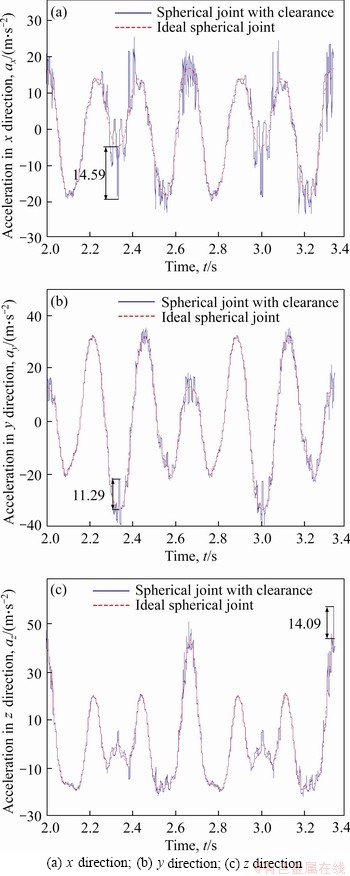
Figure 9 Acceleration change of moving platform in 3RSR parallel mechanism with moving platform��s acceleration in different directions:
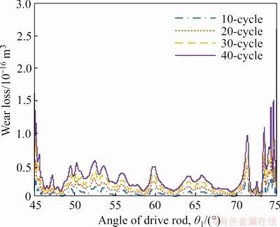
Figure 10 Change of wear loss with position of drive rod under different running cycles
The mesh parameters, n1 and n2, were both set to be 12. We selected a certain area of surface containing the maximum wear depth from the wear element through combining the azimuth coordinate and curvature radius of marked point M' in each element, as shown in Figure 11. Figure 11(a) shows the three-dimension view of the geometric reconstructed surface of the wear element. The maximum wear depth is 0.3956 mm in the selected element, which reaches 79.12% of the clearance with a value of 0.5 mm.
Figure 11(b) shows the plane view of the geometric reconstructed surface. From the partial enlarged detail, we can observe a concave phenomenon on the ball socket which was caused by wear. The solved geometric parameters of the wear were substituted into the dynamics model of the mechanism. Furthermore, the curvature radius �� of the wear element was used to replace the original radius of ball socket, Rj, in the dynamic equation. The response of the mechanism considering the wear characteristics was further solved. The contact force and the acceleration as a function of simulation time are shown in Figures 12 and 13, respectively.
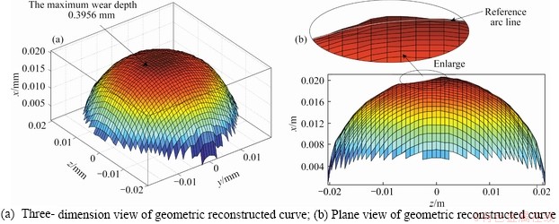
Figure 11 Geometric reconstructed curve of spherical joint with wear in 3RSR parallel mechanism:
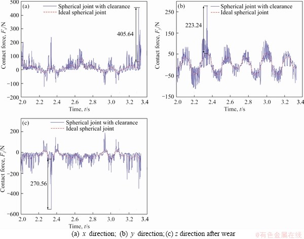
Figure 12 Change of contact force on spherical joint in 3RSR parallel mechanism with wear with contact force in different directions:
As shown in Figure 12, the maximum deviation values of the contact force between the mechanisms with and without clearance are 405.64, 223.24 and 270.56 N in the x, y and z directions, respectively. Through comparing Figure 8 and Figure 12, we can observe that the maximum deviation values increase by 418.72%, 316.41% and 207.38% in the x, y and z directions, respectively, indicating that the collision at the spherical joint with clearance is quite strong after wear.
The acceleration change of the moving platform in the 3RSR parallel mechanism with wear is shown in Figure 13. We calculated the acceleration deviation values of the moving platform. The maximum acceleration deviations with a value of 80.54, 53.28 and 60.16 m2/s in the x, y and z directions, respectively, as shown in Figure 13. Comparing with the maximum acceleration deviations shown in Figure 9, the maximum acceleration deviation values of the moving platform increase by 452.02%, 371.92% and 326.97% in the x, y and z directions, respectively. The fluctuation amplitudes of the acceleration shown in Figure 13 greatly increases compared with that in Figure 9, suggesting that wear of the spherical joint significantly increases, thereby reducing the movement stability of the mechanism.

Figure 13 Acceleration change of moving platform in 3RSR parallel mechanism with wear with acceleration of moving platform in different directions:
6 Conclusions
In this study, the dynamic model of a 3RSR parallel mechanism with spherical joint clearance and wear was built based on the modified Flores contact force model and the modified Coulomb friction model. In addition, we studied the dynamic response of the established model including contact force and acceleration. To investigate the effect of wear on the dynamic response of the model, we obtained the geometric surface reconstruction of the ball socket and substituted the Archard model to the dynamic model of the 3RSR parallel mechanism. The simulation method shown in this study may provide a reference for modelling of similar parallel mechanisms.
The reasonability of our simulation results was verified through comparing the dynamic responses of the mechanism models with and without spherical joint clearance. Moreover, the contact force of the 3RSR parallel mechanism and the acceleration of the moving platform were analyzed before and after the wear. The simulation results show that irregular wear occurred at different areas of the spherical joint with clearance in the presence of the impact and friction force. In addition, with the change of the drive rod angle, these cumulative wear losses were similar in trend and uniformly increased in numerical value every ten cycles. Long-term wear has a large effect on the dynamic response of the mechanism, thereby increasing the fluctuation of the contact force and decreasing the movement stability of the mechanism. To reveal the internal mechanism of the dynamics, the multi fields (such as thermal field) and multi-source information (such as lubrication and flexibility) will be considered into the dynamics in the subsequent studies.
Nomenclature

The attitude transformation matrix of the local coordinate system located on the component k
c
The clearance radius
cd
The coefficient of dynamic correction
ce
The coefficient of restitution
cf
The coefficient of sliding friction
dt
The time integration step
e
The clearance vector between the ball head and the ball socket
Ei, Ej
The elastic modulus
��i, ��j
The Poisson ratio
F
The collision force of ball head on the bearing
Fn
The normal contact force between the ball head and the ball socket
Ft
The expression of the tangential contact force of the ball head on the ball socket
H
The rigidity of the softer material
h
The wear depth in the element
Ixk
The moment of inertia of the drive rod or the transmission rod around the xk
Iyk
The moment of inertia of the drive rod or the transmission rod around the yk
Izk
The moment of inertia of the drive rod or the transmission rod around the zk
Ix7
The moment of inertia of the moving platform around the x7
Iy7
The moment of inertia of the moving platform around the y7
Iz7
The moment of inertia of the moving platform around the z7
K
The stiffness coefficient
lk
Length of kth drive rod or kth transmission rod
M
The mass matrix of the system
mk
Mass of the drive rod or the transmission rod
m7
Mass of the moving platform
n
The normal vector of the contact surface
pk
The standard quaternion of the local coordinate system of the component k in the fixed coordinate system
Q
The generalized force vector including the external forces and moment of external forces
q
The kinematic state of the mechanism
The generalized vector of velocity
The generalized vector of acceleration
R
Radius of the joint distribution circle on the moving platform
Ri
The radius of the ball head
Rj
The radius of the ball socket
r
Radius of the joint distribution circle on the fixed platform
rk
The coordinate of local coordinate origin on component k in the fixed coordinate system
S
The area of the element
s
The distance of the relative slip
��s��
The slip distance in the ��-th time integration step
t
The tangential vector of the contact surface
V
The volume of the wear
��V��
The wear loss in the ��-th time integration step
vt
The relative tangential velocity of collision
��(��)
The stability correction coefficient
��
The penetration depth of the ball socket
��
The wear coefficient
��
The Lagrange multiplier vector
��k
The drive angle of kth drive rod or kth transmission rod
��
The curvature radius of the element

The driving constraint equations in a 3RSR parallel mechanism

The constrained equation form of the standard quaternion

The constraint equation of the revolute joints in a 3RSR parallel mechanism

The constraint equation of each spherical joint in a 3RSR parallel mechanism

The kinematic constraint equation
The Jacobian matrix of the constraint equation
The derivative of the constraint equation versus time
Contributors
The overarching research goals were developed by HOU Yu-lei, DENG Yun-jiao and ZENG Da-xing. HOU Yu-lei conducted the literature review and established the dynamic models. ZENG Da-xing and DENG Yun-jiao solved the geometrical parameters and analyzed the dynamic response. The initial draft of the manuscript was written by HOU Yu-lei, DENG Yun-jiao and ZENG Da-xing. All authors replied to reviewers�� comments and revised the final version.
Conflict of interest
HOU Yu-lei, DENG Yun-jiao and ZENG Da-xing declare that they have no conflict of interest.
References
[1] FARAJTABAR M, DANIALI H M, VAREDI S M. Pick and place trajectory planning of planar 3-RRR parallel manipulator in the presence of joint clearance [J]. Robotica, 2017, 35(2): 241-253. DOI: 10.1017/s0263574714002768.
[2] TIAN Qiang, FLORES P, LANKARANI H M. A comprehensive survey of the analytical, numerical and experimental methodologies for dynamics of multibody mechanical systems with clearance or imperfect joints [J]. Mechanism and Machine Theory, 2018, 122: 1-57. DOI: 10.1016/j.mechmachtheory.2017.12.002.
[3] BAI Zheng-feng, ZHAO Yang. A hybrid contact force model of revolute joint with clearance for planar mechanical systems [J]. International Journal of Non-linear Mechanics, 2013, 48: 15-36. DOI: 10.1016/j.ijnonlinmec.2012.07.003.
[4] ZHANG Xu-chong, ZHANG Xian-min, CHEN Zhong. Dynamic analysis of a 3-RRR parallel mechanism with multiple clearance joints [J]. Mechanism and Machine Theory, 2014, 78: 105-115. DOI: 10.1016/j.mechmachtheory. 2014.03.005.
[5] WANG Geng-xiang, LIU Hong-zhao. Dynamics analysis of 4-SPS/CU parallel mechanism with spherical joint clearance [J]. Journal of Mechanical Engineering, 2015, 51(1): 43-51. (in Chinese)
[6] WANG Geng-xiang, LIU Hong-zhao, DENG Pei-sheng, YIN Kai-ming, ZHANG Guang-gang. Dynamic analysis of 4-SPS/CU parallel mechanism considering three-dimensional wear of spherical joint with clearance [J]. Journal of Tribology, 2017, 139(2): 021608. DOI: 10.1115/1.4034763.
[7] WANG Geng-xiang, LIU Hong-zhao. Three-dimensional wear prediction of four-degrees-of-freedom parallel mechanism with clearance spherical joint and flexible moving platform [J]. Journal of Tribology, 2018, 140(3): 031611. DOI: 10.1115/1.4038806.
[8] WANG Geng-xiang, WANG Liang. Dynamics investigation of spatial parallel mechanism considering rod flexibility and spherical joint clearance [J]. Mechanism and Machine Theory, 2019, 137: 83-107. DOI: 10.1016/j.mechmachtheory. 2019.03.017.
[9] WANG Geng-xiang, LIU Hong-zhao, DENG Pei-sheng. Dynamics analysis of spatial multibody system with spherical joint wear [J]. Journal of Tribology, 2015, 137(2): 021605. DOI: 10.1115/1.4029277.
[10] VAREDI-KOULAEI S M, DANIALI H M, FARAJTABAR M. The effects of joint clearance on the dynamics of the 3RRR planar parallel manipulator [J]. Robotica, 2017, 35(6): 1223-1242. DOI: 10.1017/s0263574715001095.
[11] SKRINJAR L, SLAVIC J, BOLTEZAR M. A review of continuous contact-force models in multibody dynamics [J]. International Journal of Mechanical Sciences, 2018, 145: 171-187. DOI: 10.1016/j.ijmecsci.2018.07.010.
[12] FLORES P, KOSHY C S, LANKARANI H M, AMBROSIO J, CLARO J C P. Numerical and experimental investigation on multibody systems with revolute clearance joints [J]. Nonlinear Dynamics, 2011, 65(4): 383-398. DOI: 10.1007/ s11071-010-9899-8.
[13] ERKAYA S. Experimental investigation of flexible connection and clearance joint effects on the vibration responses of mechanisms [J]. Mechanism and Machine Theory, 2018, 121: 515-529. DOI: 10.1016/ j.mechmachtheory.2017.11.014.
[14] MARQUES F, ISAAC F, DOURADO N, SOUTO A P, FLORES P, LANKARANI H M. A study on the dynamics of spatial mechanisms with frictional spherical clearance joints [J]. Journal of Computational and Nonlinear Dynamics, 2017, 12(5): 1-10. DOI: 10.1115/1.4036480.
[15] AMBROSIO J, POMBO J. A unified formulation for mechanical joints with and without clearances/bushings and/or stops in the framework of multibody systems [J]. Multibody System Dynamics, 2018, 42(3): 317-345. DOI: 10.1007/s11044-018-9613-z.
[16] MUKRAS S, KIM N H, MAUNTLER N A, SCHMITZ T L, SAWYER W G. Analysis of planar multibody systems with revolute joint wear [J]. Wear, 2010, 268(5-6): 643-652. DOI: 10.1016/j.wear.2009.10.014.
[17] FLORES P. Modeling and simulation of wear in revolute clearance joints in multibody systems [J]. Mechanism and Machine Theory, 2009, 44(6): 1211-1222. DOI: 10.1016/ j.mechmachtheory.2008.08.003.
[18] JIANG Qin-yu, YI Feng, LI Yu-guang, LI Bao-liang. Numerical simulation on mild wear of hinge configurations [J]. China Mechanical Engineering, 2005, 16(2): 100�C103. DOI: 10.3321/j.issn:1004-132X. 2005.02.002. (in Chinese)
[19] ASKARI E, FLORES P, DABIRRAHMANI D, APPLEYARD R. Dynamic modeling and analysis of wear in spatial hard-on-hard couple hip replacements using multibody systems methodologies [J]. Nonlinear Dynamics, 2015, 82(1-2): 1039-1058. DOI: 10.1007/s11071-015- 2216-9.
[20] MARQUES F, FLORES P, CLARO J C P, LANKARANI H M. Modeling and analysis of friction including rolling effects in multibody dynamics: A review [J]. Multibody System Dynamics, 2019, 45(2): 223-244. DOI: 10.1007/s11044- 018-09640-6.
[21] NIKRAVESH P E. Computer-aided analysis of mechanical systems [D]. New Jersey: Prentice-Hall International, Inc., 1988.
[22] FLORES P, MACHADO M, SEABRA E, TAVARES DA SILVA M. A parametric study on the Baumgarte stabilization method for forward dynamics of constrained multibody systems [C]// Proceedings of ASME 2009 International Design Engineering Technical Conferences and Computers and Information in Engineering Conference. San Diego, California, USA. 2010: 73-82. DOI: 10.1115/DETC2009- 86362.
[23] LANKARANI H M, NIKRAVESH P E. Continuous contact force models for impact analysis in multibody systems [J]. Nonlinear Dynamics, 1994, 5(2): 193-207. DOI: 10.1007/ BF00045676.
[24] MACHADO M, MOREIRA P, FLORES P, LANKARANI H M. Compliant contact force models in multibody dynamics: Evolution of the Hertz contact theory [J]. Mechanism and Machine Theory, 2012, 53: 99-121. DOI: 10.1016/ j.mechmachtheory.2012.02.010.
[25] AMBROSIO J A C. Virtual nonlinear multibody systems [M]. Dordrecht: Springer, 2003. DOI: 10.1007/978-94-010- 0203-5_4.
[26] WANG Geng-xiang, LIU Hong-zhao. Research progress of joint effects model in multibody system dynamics [J]. Chinese Journal of Theoretical and Applied Mechanics, 2015, 47(1): 31-50. DOI: 10.6052/0459-1879-14-091. (in Chinese)
[27] CHEN Xiu-long, WU Liang-kai, DENG Yu, WANG Qing. Dynamic response analysis and chaos identification of 4-UPS-UPU flexible spatial parallel mechanism [J]. Nonlinear Dynamics, 2017, 87(4): 2311-2324. DOI: 10.1007/s11071-016-3191-5.
[28] FLORES P, AMBROSIO J. Revolute joints with clearance in multibody systems [J]. Computers & Structures, 2004, 82(17-19): 1359-1369. DOI: 10.1016/j.compstruc.2004.03. 031.
(Edited by ZHENG Yu-tong)
���ĵ���
������϶��ĥ���3RSR������������ѧ��ģ�����Է���
ժҪ���˶������Ա���ش��ڼ�϶����϶�Ĵ��ڽ�������ײ��ĥ�𣬶��˶�����϶��ĥ���Ӱ���������ѧ���ԡ�����3RSR(RΪת������SΪ��)������������϶�����ڸĽ���Flores�Ӵ���ģ�ͺ�������CoulombĦ����ģ�ͣ�����ţ��-ŷ�������������Ķ���ѧģ�ͣ��������Ԫ���Լ�����̣��������Ľ�Runge-Kutta��������⣬����������ֵ��������з����Աȡ�����Archardĥ��ģ�ͣ����ĥ�����ѵļ��β������������ĥ��ı�����м����ع������������ع��������붯��ѧģ�ͣ���������ĥ�����Եĺ���϶3RSR���������Ķ���ѧ��Ӧ���������������ڳ������Ħ�������ڵ�����£����ֲ�����ĥ�𣬳���ĥ������ӽӴ����IJ������Ӷ����ͻ������˶��ȶ��ԡ�
�ؼ��ʣ���������������ѧ����϶��ĥ��ţ��-ŷ����
Foundation item: Project(2018YFB1307900) supported by the National Key R&D Program of China; Project(51775473) supported by the National Natural Science Foundation of China; Projects(E2018203140, E2019203109) supported by the Natural Science Foundation of Hebei Province, China; Project(ZD2019020) supported by the Key Research Project in Higher Education Institutions of Hebei Province, China; Project(2017KSYS009) supported by the Key Laboratory of Robotics and Intelligent Equipment of Guangdong Regular Institutions of Higher Education, China; Project(KCYCXPT2017006) supported by the Innovation Center of Robotics and Intelligent Equipment of Dongguan University of Technology, China
Received date: 2020-04-08; Accepted date: 2020-10-11
Corresponding author: ZENG Da-xing, PhD, Professor; Tel: +86-13703235420; E-mail: roboms@ysu.edu.cn; ORCID: https://orcid.org/ 0000-0003-0577-0162

