不同接触压力和电极间距下AgTiB2触头的材料转移行为
来源期刊:中国有色金属学报(英文版)2019年第5期
论文作者:习勇 王献辉 周子敬 李航宇 国秀花
文章页码:1046 - 1056
关键词:Ag基触头材料;接触压力;电极间距;材料转移;电弧侵蚀
Key words:Ag-based contact materials; contact force; electrode gap; material transfer; arc erosion
摘 要:为了阐明接触压力和电极间距对Ag基触头材料转移行为的影响,在阻性负载24 V/16 A条件下对Ag-4wt.%TiB2触头材料在电接触测试系统中进行不同接触压力和电极间距5000次电弧侵蚀实验, 系统研究燃弧能量和燃弧时间与接触压力和电极间距的关系,表征电弧侵蚀后阳极和阴极的表面形貌,测量电弧侵蚀后两电极的质量变化,并对材料转移行为进行讨论。研究结果表明:接触压力显著影响燃弧能量、燃弧时间和侵蚀形貌,但并不改变材料转移模式。然而,电极间距不但影响燃弧能量、燃弧时间和侵蚀形貌,而且改变材料转移方向。当电极间距为1 mm时,材料转移方向为由阳极到阴极;而电极间距为4 mm时,材料转移方向发生逆转,即材料由阴极向阳极转移。
Abstract: To disclose the effect of contact force and electrode gap on the material transfer behavior of Ag-based contact material, arc-erosion tests of the Ag-4wt.%TiB2 contact material were performed for 5000 operations at 24 V/16 A under resistive load on an electric contact material testing system. The arc energy and arc duration were investigated, the surface morphologies of eroded anode and cathode were characterized, the mass changes after arc-erosion tests were determined, and the material transfer behavior was discussed as well. The results show that contact force has a significant effect on the arc energy, arc duration and erosion morphology, but has no impact on the material transfer mode. However, electrode gap not only influences the arc energy, arc duration and surface morphology, but also changes the material transfer mode. At 1 mm, the material transfers from anode to cathode. Nevertheless, an opposite mode presents at 4 mm, which is from cathode to anode.
Trans. Nonferrous Met. Soc. China 29(2019) 1046-1056
Yong XI1, Xian-hui WANG1, Zi-jing ZHOU1, Hang-yu LI1, Xiu-hua GUO2
1. Shaanxi Key Laboratory of Electrical Materials and Infiltration Technology, Xi’an University of Technology, Xi’an 710048, China;
2. School of Materials Science and Engineering, Henan University of Science and Technology, Luoyang 471003, China
Received 19 June 2018; accepted 14 January 2019
Abstract: To disclose the effect of contact force and electrode gap on the material transfer behavior of Ag-based contact material, arc-erosion tests of the Ag-4wt.%TiB2 contact material were performed for 5000 operations at 24 V/16 A under resistive load on an electric contact material testing system. The arc energy and arc duration were investigated, the surface morphologies of eroded anode and cathode were characterized, the mass changes after arc-erosion tests were determined, and the material transfer behavior was discussed as well. The results show that contact force has a significant effect on the arc energy, arc duration and erosion morphology, but has no impact on the material transfer mode. However, electrode gap not only influences the arc energy, arc duration and surface morphology, but also changes the material transfer mode. At 1 mm, the material transfers from anode to cathode. Nevertheless, an opposite mode presents at 4 mm, which is from cathode to anode.
Key words: Ag-based contact materials; contact force; electrode gap; material transfer; arc erosion
1 Introduction
Electrical contacts, the key components of electrical switches, undertake the task of turning on and off the circuit, and their performances remarkably affect the reliability, stability and service life of the integral electrical system [1-3]. Ag-based contact materials are extensively used in the low-voltage electrical appliances due to their excellent electrical conductivity, arc erosion and welding resistance [4,5]. During service, arc erosion occurs at make and break operations, resulting in the material transfer between anode and cathode, and change of the surface morphology of both electrodes. If serious, it delays the contact process or causes the failure of electrical contacts [6]. To understand the arc erosion characteristics of Ag-based contact materials, a number of investigations have been made on the effect of the second phase (B2O3 [7], SnO2 [8,9], WC [10], ZnO [11], CuO [12], Ti3AlC2 [13]), particle size [4,14] and minor additives (WO3 [15], CuO [16], Bi2O3[17], etc) on the arc erosion behavior, and it is revealed that appropriate second phase and additive can significantly enhance arc erosion resistance. Currently, the material transfer mechanism has been investigated. CHEN and KOICHIRO [18] believed that material transfer depends on which ion can sustain the arc combustion. The metallic ions trigger the material transfer from anode to cathode, while the gaseous ions cause the material transfer from cathode to anode. DOUBLET et al [19] thought that material transfer mode is related to the arc length. The short arc leads to the material transfer from anode to cathode, whereas long arc makes the material transfer from cathode to anode. BIYIK and AYDIN [20] found that the material transfer mode reverses with increasing current. CHEN and SAWA [21] confirmed that the critical current transition from metallic ion arc to gaseous ion arc depends on the voltage, and high voltage results in small critical current. SWINGLER and MCBRIDE [22] thought that the material transfer of AgCdO and AgSnO2 electrode contacts is attributed to the evaporation of the cathode and the condensation of the anode at small current. They found that splash is much easier to generate at high current, and the AgCdO contact material has lower erosion rate than AgSnO2 contact material. RIEDER and WEICHSLER [23] revealed that the viscosity of the molten pool dramatically affects the mass loss of AgCdO and AgSnO2 contact materials. Due to higher molten pool viscosity, AgSnO2 contact material has less splash in comparison with AgCdO contact material.
Though AgCdO and AgSnO2 contact materials have outstanding resistance to arc erosion, wear and welding [24], the toxic nature of Cd and its oxide along with an increasing environmental awareness limits the applications of AgCdO contact material [25], and the separation of SnO2 particles and Ag particles during long time service for AgSnO2 contact material causes larger contact resistance and higher temperature rise, which dramatically affects the reliability of electrical systems. To tackle these issues, WANG et al [26] proposed to utilize conductive TiB2 intermetallic compound to substitute SnO2 as strengthening phase in the Ag-based contact material, and found that a certain amount of TiB2 can well disperse the arc, improve the arc erosion and welding resistance [27]. LI et al [28] found that the material transfer mode of AgTiB2 contact material is from cathode to anode at small current, whereas it presents an opposite mode at high current. LI et al [29] believed that voltage has a remarkable effect on material transfer mode. The material transfer is from anode to cathode for the Ag-4wt.%TiB2 and Ag-4wt.%SnO2 contact materials at 24 V, whereas it converts from cathode to anode at 36 V. In addition, they also found that fine strengthening particles are favorable for decreasing the mass loss and relative mass transfer.
Though it can acquire more understanding of the material transfer behavior from above investigations, the material transfer, due to the complexity during electrical contact process, is affected by many factors, such as electrical parameters, material characteristics and mechanical factors. However, the effect of mechanical factors on the material transfer behavior has been still obscure so far. To get more deep insights of the material transfer behaviors of Ag-based contact material, the arc-erosion tests were performed for 5000 operations at 24 V/16 A under different contact forces and electrode gaps for Ag-4wt.%TiB2 contact material prepared by balling milling and powder metallurgy, a process that is favorable for homogeneous microstructure [30-32].
2 Experimental
The starting materials were Ag powder (purity 99.9 wt.%, particle size 72 μm) and TiB2 powder (purity 99.9 wt.%, particle size 60 nm). In the present work, the following process parameters were selected based on our previous work [14,26,33]. The Ag-TiB2 compound powders with a mass ratio of 96:4 were mixed at a planetary ball mill (KQM-YB/B, Xianyang Jinhong Machinery Co., Ltd.) at 300 r/min for 4 h and a ball-to-powder ratio of 15:1. The ethyl alcohol and polyvinylpyrrolidone (1 wt.%) were used as process control agent and dispersant, respectively. The mixture was compressed under a pressure of 200 MPa for 30 s to obtain a compact with a diameter of 21 mm and a length of 10 mm, followed by sintering at 750 °C for 2 h at 30 MPa in a hot-pressing furnace (SLQ-16B, Xi’an University of Technology) under the protective atmosphere of nitrogen gas.
The as-prepared specimens were machined into the electrode with a diameter of 3.8 mm and a length of 6 mm along with an arc-shaped surface by wire electrical discharge machining (WEDM) and grinding machine. The arc-erosion tests were performed on an electric contact material testing system (JF04C, Kunming Institute of Precious Metals), and the cathode and anode were used as the stationary contact and movable contact, respectively. Five contact pairs were respectively performed for 5000 operations at the contact force of 0.2, 0.4 and 0.8 N and the electrode gap of 1 and 4 mm under the resistive load with a DC current of 16 A and voltage of 24 V, and the operation frequency of 1 Hz. It should be stated that electrode gap refers to the maximum distance between cathode and anode during arc-erosion test, while the contact force is a compressive force when anode touches cathode. During arc-erosion tests, the anode moved downward until it contacted the cathode, and then moved upward. The data of arc duration and energy were automatically collected and recorded by the JF04C electrical contact material testing system. The mass before and after arc-erosion test was determined by an electrical balance (TG328A, Tianjin Shunnuo Instrument Technology Co., Ltd.). The mass loss was calculated by each electrode mass before and after arc-erosion test. The relative transfer mass was determined by the difference of the anode and cathode mass after arc-erosion test. The surface morphologies of the arc-eroded specimens were characterized by a scanning electron microscope (JSM-6700F, Nippon Electric Company Ltd.).
3 Results
3.1 Arc energy and arc duration under different contact forces
The average arc energy and arc duration of the Ag-4wt%TiB2 contact material under different contact forces are shown in Fig. 1. As seen from Fig. 1(a), the make-arc energy sharply decreases from 0.2 to 0.4 N, followed by a slight increase with increasing contact force. Compared with make-arc energy, the break-arc energy, however, presents a different tendency, which is much less than the make-arc energy. Furthermore, the break-arc energy has a slight increase from 0.2 to 0.4 N, followed by an approximately 50% decrease at 0.8 N (see Fig. 1(b)). Nevertheless, the break-arc duration gradually decreases with increasing contact force.
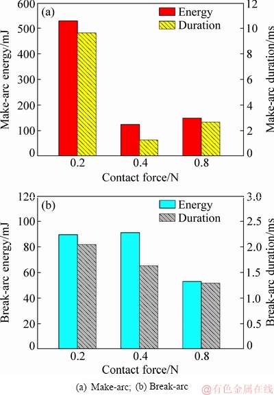
Fig. 1 Average arc energy and arc duration of Ag-4wt.%TiB2 contact material under different contact forces
To get more understanding of the change of arc energy at different contact forces, the distribution of arc energy is shown in Fig. 2. As seen from Fig. 2(a), the make-arc energy fluctuates in the range of 0-3000 mJ at 0.2 N. However, it presents a concentrated distribution at 0.4 and 0.8 N (see Fig. 2(b) and Fig. 2(c)), indicating that high contact force reduces the fluctuation of make-arc energy.
As seen from Fig. 2(a1) and Fig. 2(b1), the break-arc energy has a disperse distribution when the contact force is below 0.4 N, but the break-arc energy is concentrated in the range of 0-150 mJ at 0.8 N (see Fig. 2(c1)). This suggests that contact force has a remarkably influence on the distribution of arc energy.
3.2 Surface morphologies of eroded anode and cathode under different contact forces
Figure 3 shows the surface morphologies of eroded anode and cathode for the Ag-4wt.%TiB2 contact material under 0.2, 0.4 and 0.8 N. As seen from Fig. 3(a), at 0.2 N, a large erosion pit appears at the center of the anode, whereas some pores and solidified traces occur at the cathode surface (see Fig. 3(a1)). At 0.4 N, it can be seen from Fig. 3(b) that erosion pits also generate at the center of anode, and solidified traces still present at the cathode surface along with more less-erosion area (see Fig. 3(b1)). However, the morphologies of anode and cathode apparently change at 0.8 N, and numbers of tiny erosion pits generate at the anode surface (see Fig. 3(c) and Fig. 3(c1)). Meanwhile, the pores almost disappear. This suggests that contact force has a dramatic effect on the arc erosion of both anode and cathode.
3.3 Mass change of eroded anode and cathode under different contact forces
Table 1 gives the mass change of anode and cathode before and after arc-erosion tests under 0.2, 0.4 and 0.8 N for Ag-4wt.%TiB2 contact material. For the contact pairs under three contact forces, the mass changes of these three eroded anodes are -3.26, -1.82 and -1.78 mg, whereas the mass changes for corresponding eroded cathodes are -1.20, -0.42 and -0.69 mg, respectively. Obviously, for the three contact pairs, the cathodes have less mass loss than the counterpart anodes.
To clarify the material transfer mode of the Ag-4wt.%TiB2 contact material, the direction and mass of material transfer are determined by the relative mass of the anode and cathode. Here, the relative mass refers to the difference between anode mass and cathode mass after arc-erosion test. At the contact force of 0.2, 0.4 and 0.8 N, the relative transfer mass are 2.06, 1.40 and 1.09 mg, respectively. It is revealed that high contact force enhances the resistance to material transfer. As aforementioned, the anode presents larger mass loss than the cathode under the three contact forces. Subsequently, it is believed that the material transfer mode is from anode to cathode.
3.4 Arc energy and arc duration at different electrode gaps
Figure 4 shows the average arc energy and arc duration of the Ag-4wt.%TiB2 contact material at different electrode gaps. The make-arc energy at 4 mm is reduced by 50% in comparison with that at 1 mm. Moreover, the break-arc energy at 4 mm is 1.5 times higher than that at 1 mm. Additionally, it is also found that make-arc energy is always higher than break-arc energy in the two cases. Nevertheless, the difference between make-arc energy and break-arc energy decreases with increasing electrode gap. In addition, arc duration presents a similar tendency.
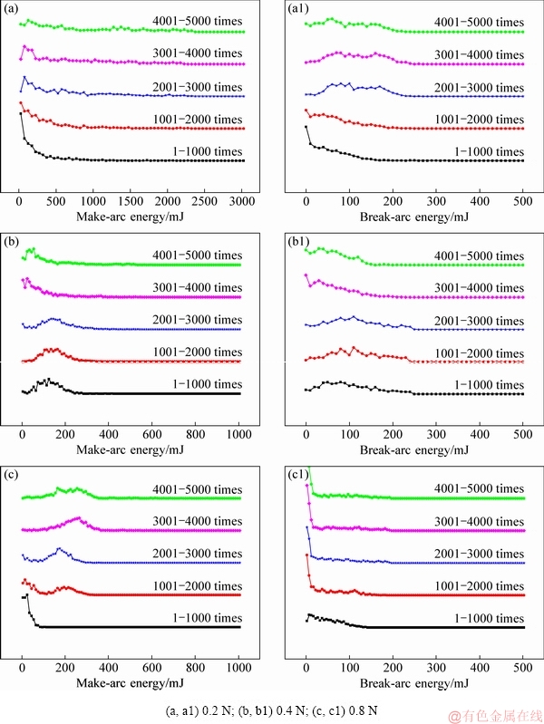
Fig. 2 Distributions of make-arc energy (a-c) and break-arc energy (a1-c1) for Ag-4wt.%TiB2 contact material under different contact forces
Figure 5 shows the distribution of make-arc energy and break-arc energy at different electrode gaps. As seen from Fig. 5(a), the make-arc energy is mainly distributed in the range of 100-400 mJ at 1 mm; however, at 4 mm, the make-arc energy is distributed in the range of 0-300 mJ (see Fig. 5(b)). In general, the make-arc energy has a similar distribution at different electrode gaps. Moreover, the break-arc energy has the same tendency as make-arc energy. Subsequently, it is thought that electrode gap influences arc energy despite of a little change on their distribution.
3.5 Morphology of eroded anode and cathode at different electrode gaps
Figure 6 shows the morphologies of eroded anode and cathode for Ag-4wt.%TiB2 contact material at different electrode gaps. At 1 mm, a crater occurs on the anode surface along with large numbers of small erosion pits at the center of anode (see Fig. 6(a)), whereas several protrusions along with a solidified layer at the cathode surface (see Fig. 6(a1)). At 4 mm, there is slight concave at the center of the anode (see Fig. 6(b)) and many tiny erosion pits appear at the center of the cathode (see Fig. 6(b1)).
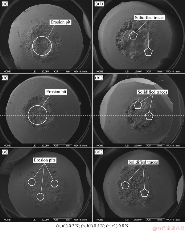
Fig. 3 Surface morphologies of eroded anode (a-c) and cathode (a1-c1) for Ag-4wt.%TiB2 contact material under different contact forces
Table 1 Mass change of anode and cathode for Ag-4wt.%TiB2 contact material after arc-erosion tests under different contact forces
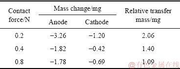
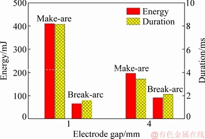
Fig. 4 Average arc energy and arc duration of Ag-4wt.%TiB2 contact material at different electrode gaps
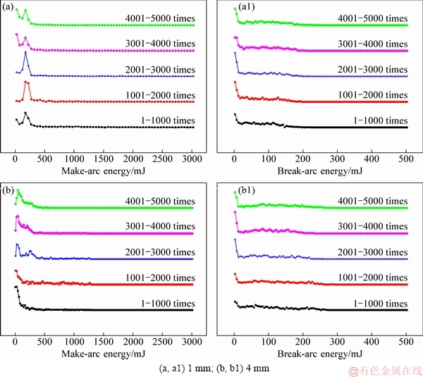
Fig. 5 Distributions of arc energy for Ag-4wt.%TiB2 contact material at different electrode gaps
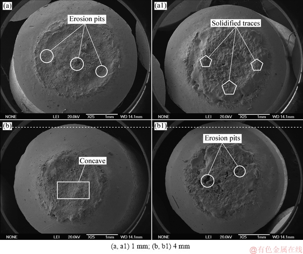
Fig. 6 Surface morphologies of eroded anode (a, b) and cathode (a1, b1) for Ag-4wt.%TiB2 contact material at different electrode gaps
3.6 Mass changes of eroded anode and cathode at different electrode gaps
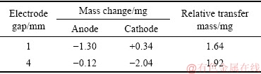
Table 2 lists the mass changes of eroded anode and cathode for the Ag-4wt.%TiB2 contact material at different electrode gaps. At 1 mm, the anode mass loses while the cathode mass gains, suggesting that the material transfers from anode to cathode. However, at 4 mm, the mass loss at the cathode is much higher than that at the anode, indicating that the material transfer mode is changed. In this case, the material transfers from cathode to anode.
Table 2 Mass change of anode and cathode for Ag-4wt.%TiB2 contact material at different electrode gaps
4 Discussion
4.1 Contact force
4.1.1 Effect of contact force on arc energy and arc duration
As mentioned in Section 3.1, the make-arc energy decreases drastically and then increases slowly. Nevertheless, the break-arc duration reduces progressively, indicating that contact force has a remarkable effect on the arc energy and arc duration. This can be explained as follows.
Make operation can be divided into three stages: pre-breakdown, spot contact and melting, elastoplastic deformation and recovery.
(1) Pre-breakdown stage
It is well known that arc generates in the stage of pre-breakdown once gas is broken down when the electrode gap is less than a certain value. LI et al [29] thought that the electrode surface is not very flat at the microscopic level, which comprises of a lot of spikes and concaves. The rough surface results in an uneven distribution of the electric field. SWINGLER and SUMPTION [34] found that an arc prefers to generate at the spot with higher electric field. Hence, arc generated at high electric field causes the electrode material to melt in the vicinity of the spot until extinction, and then the arc hops to the next spot with another high electric field, giving rise to the melting of spikes at the electrode (see Fig. 7).
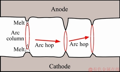
Fig. 7 Schematic diagram of arc hop
(2) Spot contact and melting stage
As the anode moves downward to the cathode, one or several spots contact and the current passes through these spots. Figure 8 shows the schematic diagram of the conductive spot contact and melting stage under different ontact forces. Once the two spikes contact, the concentrated current generates a large amount of heat, which results in the melting of the conductive spots, thus increasing the distance between the two spots. As the anode moves downward further, the next conductive spots will switch on the circuit (see Fig. 8(b)). Subsequently, it is easier for the current to pass through the new conductive spots, resulting in the melting of this region.
At low contact force, only a few spots contact at the surface of electrodes with a large current density (see Fig. 8(b)). The contact resistance in the case of multi-spot contact can be calculated by the method proposed by GREENWOOD [35] as follows:
 (1)
(1)
where ρ is resistivity of metal conductor, ai is the radius of the conductive spot, n is the number of the conductive spot and dij is the distance between the conductive spot i and j.
At low contact force, there are small numbers of conductive spots, thus causing the current concentration. Nevertheless, it is learnt from Eq. (1) that the contact resistance increases in this case. Therefore, a large amount of heat generates at these conductive spots, leading to melting or evaporation of the electrode material. Due to the high electrical conductivity of Ag vapor, arc can last much longer and further promote more melting or evaporation. Hence, the maximum make-arc energy occurs at 0.2 N. Because only small numbers of conductive spots contact at this moment, each spot has a greater influence on the arc energy and distribution. However, high contact force enhances contact of more conductive spots, and thus, small current passes at each spot (see Fig. 8(c)). According to Eq. (1), the contact resistance decreases accordingly, and less heat generates at these conductive spots. In addition, the higher contact force also brings about more mechanical wear. Subsequently, the make-arc energy at 0.4 N decreases sharply compared with that at 0.2 N.
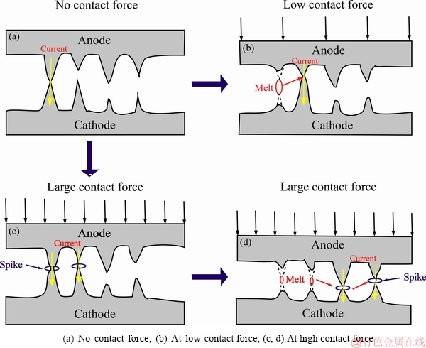
Fig. 8 Schematic diagram of conductive spot contact and melting stage during make operation
(3) Elastoplastic deformation and recovery stage
With progressively downward motion of anode, more conductive spots contact gradually. In this case, due to the applied contact force, vertical upward and downward forces occur at the anode and cathode surface, respectively. GUO et al [36] thought that an elastic contact generates at the initial stage, followed by a short-term separation and subsequent elastoplastic recovery. The separated anode bounces back and forth to the original stage, and subsequently moves downward until stable contact and arc extinguishment. At the spot contact and melting stage, it is likely that there are enough numbers of conductive spots during make operation, which results in the almost same Joule heat generated by the current. However, high contact force increases the elastomeric recovery of the contact surface, causing large contact probability and further more melting and higher arc energy. This can explain why the make-arc energy increases slowly when the contact force increases from 0.4 to 0.8 N. Due to more contact of conductive spots, the current density decreases at these sites, thus giving rise to the concentrated distribution of make-arc energy (see Fig. 2(b) and Fig. 2(c)).
CHEN et al [37] believed that break arc is derived from the ionization of metal atoms and gas atoms after the burst of the molten bridge. In fact, the molten bridges present different widths and shapes during break operation. With further separation of the electrodes, the molten bridges are elongated progressively, resulting in the increased contact resistance and temperature rise. Figure 9 shows schematic diagram of the molten bridge burst. For the long and thin molten bridge, the higher current density causes the burst of the molten bridge at the sites A-A1, as shown in Fig. 9(a). Once the current passes through another molten bridge, which also brings about the increase of current density at the sites B-B1 and C-C1 (see Fig. 9(b) and Fig. 9(c)). In addition, the further separation of the electrodes also increases the contact resistance. Thereby, the sharp temperature rise generated causes the molten bridge to burst one by one, which gives rise to more metal vapor, and the formation of metallic ion due to the collisions of metal vapor with the electrons (see Fig. 9(d)).
With more contact of conductive spots at high contact force, more molten bridges burst, leading to less current density and shorter arc duration. On the other hand, the distribution of break-arc energy is concentrated because the current distributes uniformly on more contact points, which can be verified by the results shown in Fig. 2(c1).
4.1.2 Effect of contact force on morphology of eroded anode and cathode
As learnt from Section 3.2, the eroded anode and cathode have different morphologies at low and high contact force. This can be interpreted as follows.
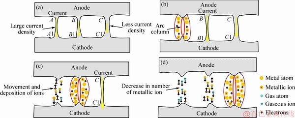
Fig. 9 Schematic diagram of molten bridge burst
As discussed in section 4.1.1, small numbers of conductive spots are subjected to higher current density at low contact force, resulting in the thermal accumulation at these sites, sharp temperature rise and more gas trapped in the melt. When the arc is extinguished, the temperature of the molten pool decreases rapidly, giving rise to gas escape from the molten pool, and the formation of crack and pores at the electrode surface. Furthermore, a higher temperature gradient also causes the spikes and protrusions to melt rapidly. However, many conductive spots undergo less current density at high contact force, which reduces the temperature gradient of the electrodes. In this case, the pores are not easy to form, and heat generated by arcing disperses in a larger area, thus causing less arc erosion at an appropriate contact force.
4.1.3 Effect of contact force on relative mass change
As mentioned in Section 3.3, the contact force does not change the material transfer mode. However, the relative mass change decreases with increasing contact force. This is because higher contact force causes the current to disperse in a large number of conductive spots and reduces the current density, thus giving rise to less evaporation and splash.
4.2 Electrode gap
4.2.1 Effect of electrode gap on arc energy and arc duration
As mentioned in Section 4.1.1, the breakdown gas causes arc generation if the electrode gap is less than a certain value. At 1 mm, due to the small electrode gap, the electric field is fairly high between the two electrodes, which promotes arc hop, resulting in melting and evaporation of the contact surface. The Ag vapor generated further promotes arc hop and combustion, causing more melting and evaporation. Nevertheless, the electric field decreases at 4 mm, thus reducing Ag evaporation. In addition, with increasing electrode gap, Ag vapor is progressively depleted during motion and diffusion, and thus, the number of ions that sustain the arc combustion is reduced and the make-arc energy is decreased.
As described in Section 4.1.2, the break arc is generated by the burst of the molten bridge. At 1 mm, the molten bridge with a less length and a larger diameter, results in less current density and lower arc energy. At 4 mm, the elongated molten bridge decreases its diameter, leading to the increased current density. In addition, the larger electrode gap causes more originally-molten bridges to burst and the generation of larger arc energy.
4.2.2 Effect of electrode gap on material transfer behavior
Based on the motion and deposition of microscopic particle [18], the material transfer behavior can be explained as follows. JEMAA et al [38] revealed that the material transfer depends on which is dominant for anodic arc and cathodic arc. At 1 mm, make-arc energy is much higher than break-arc energy. Thereby, it is believed that the material transfer is mainly dominated by the make arc. The electrons collide with the Ag vapor generated during the pre-breakdown stage, and the Ag+ deposits on the cathode surface under the action of the electric field, causing the formation of solidified traces at the cathode surface.
At 1 mm, higher make-arc energy generates more heat, which increases the number of electrons emitted from the cathode. This not only promotes the collisions of more electrons with Ag vapor, but also brings about more electrons to bombard the anode, resulting in the material transfer from anode to cathode. At 4 mm, during make operation, Ag+ deposition and less electron bombardment on the anode reduce the anodic erosion. Once the electrode gap reaches a certain value, the gas becomes the dominant medium during break operation. The gaseous cations bombard the cathode, thus generating many erosion pits at the cathode surface. Subsequently, the increased electrode gap decreases anodic erosion and increases cathodic erosion, causing the reversal of the material transfer mode.
5 Conclusions
(1) With increasing contact force, make-arc energy decreases sharply and then increases slowly, whereas break-arc energy increases and then decreases. Moreover, the distribution of make-arc energy and break-arc energy tends to be concentrated. This can be ascribed to the change of the number of conductive spots.
(2) The relative transfer mass decreases with contact force, but the material transfer still presents the same mode from anode to cathode.
(3) The large electrode gap decreases make-arc energy and increases the break-arc energy, but has no obvious effect on their distribution.
(4) The electrode gap changes the material transfer mode. At 1 mm, the material transfers from anode to cathode, while an opposite material transfer mode occurs at 4 mm.
References
[1] LI Jin, MA Guang, SUN Xiao-liang, WANG Yi, ZHENG Jing. Preparation fundamental and outlook of AgSnO2 electrical contact material [J]. Electrical Engineering Materials, 2011, 3: 3-9. (in Chinese)
[2] LI Wen-sheng, LI Ya-ming, ZHANG Jie, LIU Yi, DONG Hong-feng. Progress in the research and application of silver-based electrical contact materials [J]. Materials Review, 2011, 25: 34-39. (in Chinese)
[3] LIU Yi-chun, XIE Ming, ZHANG Jia-min, YAN Ji-kang, DU Jing-hong, GAN Guo-you, YI Jian-hong. An overview on the preparation methods of AgSnO2 electrical contact materials [J]. Materials Review, 2013, 10: 60-64. (in Chinese)
[4] ZHANG Miao, WANG Xian-hui, YANG Xiao-hong, ZOU Jun-tao, LIANG Shu-hua. Arc erosion behaviors of AgSnO2 contact materials prepared with different SnO2 particle sizes [J]. Transactions of Nonferrous Metals Society of China, 2016, 26: 783-790.
[5] WU Chun-ping, YI Dan-qing, WENG Wei, LI Su-hua, ZHOU Jie-min. Influence of alloy components on arc erosion morphology of Ag/MeO electrical contact materials [J]. Transactions of Nonferrous Metals Society of China, 2016, 26: 185-195.
[6] XU Yun, GUO Ying-chun, LIU Fang-fang, GENG Yong-hong, ZHANG Kun-hua. Study on arc erosion of Ag-La2NiO4 contact materials [J]. Precious Metals, 2007, 3: 15-19. (in Chinese)
[7] Biyik S, Arslan F, Aydin M. Arc-erosion behavior of boric oxide-reinforced silver-based electrical contact materials produced by mechanical alloying [J]. Journal of Electronic Materials, 2015, 44: 457-466.
[8] Biyik S, Aydin M. Fabrication and arc-erosion behavior of Ag-8SnO2 electrical contact materials under inductive loads [J]. Acta Physica Polonica A, 2017, 131: 339-342.
[9] Wang J, Li D M, Wang Y P. Microstructure and properties of Ag-SnO2 materials with high SnO2 content [J]. Journal of Alloys and Compounds, 2014, 582: 1-5.
[10] Ray N, Kempf B, Mützel T, Froyen L, Vanmeensel K, Vleugels J. Effect of WC particle size and Ag volume fraction on electrical contact resistance and thermal conductivity of Ag-WC contact materials [J]. Materials & Design, 2015, 85: 412-422.
[11] Wei Z J, Zhang L J, Shen T, Qiao Z Y, Yang H, Fan X P, Chen L S. Effects of oxide-modified spherical ZnO on electrical properties of Ag/ZnO electrical contact material [J]. Journal of Materials Engineering and Performance, 2016, 25: 3662-3671.
[12] Wang J, Kang Y Q, Wang C. Microstructure and vacuum arc characteristics of CuO skeletal structure Ag-CuO contact materials [J]. Journal of Alloys and Compounds, 2016, 686: 702-707.
[13] Ding J, Tian W B, Zhang P, Zhang M, Zhang Y M, Sun Z M. Arc erosion behavior of Ag/Ti3AlC2 electrical contact materials [J]. Journal of Alloys and Compounds, 2018, 740: 669-676.
[14] Wang Xian-hui, Yang Hao, Liang Shu-hua, Liu Ma-bao, Liu Qi-da. Effect of TiB2 particle size on erosion behavior of Ag-4wt%TiB2 composite [J]. Rare Metal Materials and Engineering, 2015, 44: 2081-2085. (in Chinese)
[15] Li H Y, Wang X H, Xi Y, Liu Y F, Guo X H. Influence of WO3 addition on the material transfer behavior of the AgTiB2 contact material [J]. Materials & Design, 2017, 121: 85-91.
[16] Wang J, Liu W, Li D M, Wang Y P. The behavior and effect of CuO in Ag/SnO2 materials [J]. Journal of Alloys and Compounds, 2014, 588: 378-383.
[17] Chen Mei, Wang Xian-hui, Zou Jun-tao, Liang Shu-hua. Effect of additives on microstructure and properties of novel AgTiB2 composite [J]. Rare Metal Materials and Engineering, 2012, 41: 2228-2232. (in Chinese)
[18] CHEN Z K, KOICHIRO S. Effect of arc behavior on material transfer: A review [J]. IEEE Transactions on Components Packaging Manufacturing Technology-Part A, 1998, 21: 310-322.
[19] DOUBLET L, JEMAA N B, HAUNER F, JEANNOT D. Make arc erosion and welding tendency under 42VDC in automotive area [C]//Proc 49th IEEE Holm Conference Electrical Contacts. 2003, 158-162.
[20] BIYIK S, AYDIN M. Investigation of the effect of different current loads on the arc-erosion performance of electrical contacts [J]. Acta Physica Polonica A, 2016, 129: 656-660.
[21] CHEN Z K, SAWA K. Particle sputtering and deposition mechanism for material transfer in breaking arcs [J]. Journal of Applied Physics, 1994, 76: 3326-3331.
[22] SWINGLER J, MCBRIDE J W. The erosion and arc characteristics of AgCdO and AgSnO2 contact materials under DC break conditions [J]. IEEE Transactions on Components Packaging Manufacturing Technology-Part A, 1996, 19: 404-415.
[23] RIEDER W, WEICHSLER V. Make erosion mechanism of AgCdO and AgSnO2 contacts [J]. IEEE Transactions on Components Hybrids Manufacturing Technology, 1992, 15: 332-338.
[24] COSOVIC V, COSOVIC A, TALIJAN N, ZIVKOVIC D, MANASIJEVIC D, MINIC D. Improving dispersion of SnO2 nanoparticles in AgSnO2 electrical contact materials using template method [J]. Journal of Alloys and Compounds, 2013, 567: 33-39.
[25] WANG Hai-tao, WANG Jing-qi, DU Jiang, MENG Fan-qing. Influence of rare earth on the wetting ability of AgSnO2 Contact Material [J]. Rare Metal Materials and Engineering, 2014, 43: 1846-1849. (in Chinese)
[26] WANG X H, LI G J, ZOU J T, LIANG S H, FAN Z K. Investigation on preparation, microstructure and properties of AgTiB2 composite [J]. Journal of Composite Materials, 2011, 45: 1285-1293.
[27] LI Gui-jing, WANG Xian-hui, ZOU Jun-tao, LIANG Shu-hua. Investigation on arc erosion behavior of AgTiB2 composite [J]. Precious Metals, 2011, 32: 36-41. (in Chinese)
[28] LI H Y, WANG X H, GUO X H, YANG X H, LIANG S H. Material transfer behavior of AgTiB2 and AgSnO2 electrical contact materials under different currents [J]. Materials & Design, 2017, 114: 139-148.
[29] LI H Y, WANG X H, LIU Y F, GUO X H. Effect of strengthening phase on material transfer behavior of Ag-based contact materials under different voltages [J]. Vacuum, 2017, 135: 55-65.
[30] Biyik S. Characterization of nanocrystalline Cu25Mo electrical contact material synthesized via ball milling [J]. Acta Physica Polonica A, 2017, 132: 886-888.
[31] Biyik S, Aydin M. The effect of milling speed on particle size and morphology of Cu25W composite powder [J]. Acta Physica Polonica A, 2015, 127: 1255-1260.
[32] Biyik S, Aydin M. Optimization of mechanical alloying parameters of Cu25W electrical contact material [J]. Acta Physica Polonica A, 2017, 132: 909-912.
[33] Wang X H, Yang H, Chen M, Zou J T, Liang S H. Fabrication and arc erosion behaviors of AgTiB2 contact materials [J]. Powder Technology, 2014, 256: 20-24.
[34] SWINGLER J, SUMPTION A. Arc erosion of AgSnO2 electrical contacts at different stages of a break operation [J]. Rare Metals, 2010, 29: 248-254.
[35] GREENWOOD J A. Constriction resistance and the real area of contact [J]. British Journal of Applied Physics, 1966, 17: 1621-1632.
[36] GUO Ying-chun, GENG Yong-hong, CHEN Song, ZHANG Kun-hua, GUAN Wei-ming. DC electric erosion of electric contacts [J]. Rare Metal Materials and Engineering, 2007, 36: 264-268. (in Chinese)
[37] CHEN Z K, MIZUKOSHI H, SAWA K. Contact erosion patterns of Pd material in DC breaking arcs [J]. IEEE Transactions on Components Packaging Manufacturing Technology-Part A, 1994, 17: 61-69.
[38] JEMAA N B, MORIN L, BENHENDA S, NEDELEC L. Anode to cathode arc transition according to break arc lengthening [J]. IEEE Transactions on Components Packaging Manufacturing Technology- Part A, 1998, 21: 599-603.
习 勇1,王献辉1,周子敬1,李航宇1,国秀花2
1. 西安理工大学 陕西省电工材料与熔(浸)渗技术重点实验室,西安 710048;
2. 河南科技大学 材料科学与工程学院,洛阳 471003
摘 要:为了阐明接触压力和电极间距对Ag基触头材料转移行为的影响,在阻性负载24 V/16 A条件下对Ag-4wt.%TiB2触头材料在电接触测试系统中进行不同接触压力和电极间距5000次电弧侵蚀实验, 系统研究燃弧能量和燃弧时间与接触压力和电极间距的关系,表征电弧侵蚀后阳极和阴极的表面形貌,测量电弧侵蚀后两电极的质量变化,并对材料转移行为进行讨论。研究结果表明:接触压力显著影响燃弧能量、燃弧时间和侵蚀形貌,但并不改变材料转移模式。然而,电极间距不但影响燃弧能量、燃弧时间和侵蚀形貌,而且改变材料转移方向。当电极间距为1 mm时,材料转移方向为由阳极到阴极;而电极间距为4 mm时,材料转移方向发生逆转,即材料由阴极向阳极转移。
关键词:Ag基触头材料;接触压力;电极间距;材料转移;电弧侵蚀
(Edited by Bing YANG)
Foundation item: Projects (51274163, 51605146) supported by the National Natural Science Foundation of China; Project (U1502274) supported by Key Program of the National Natural Science Foundation of China; Project (2018M632769) supported by the China Postdoctoral Science Foundation; Project (2017SKY-WK010) supported by the Research Fund of Shaanxi Key Laboratory of Comprehensive Utilization of Tailings Resources, China; Project (18JK0722) supported by Special Research Program of Shaanxi Provincial Department of Education, China
Corresponding author: Xian-hui WANG; Tel: +86-29-82312185; E-mail: xhwang693@xaut.edu.cn
DOI: 10.1016/S1003-6326(19)65013-2

