Influence of water-rich tunnel by shield tunneling on existing bridge pile foundation in layered soils
来源期刊:中南大学学报(英文版)2021年第8期
论文作者:周德泉 黄戡 孙逸玮 李宇健 蒋萌 黄先强
文章页码:2574 - 2588
Key words:shield tunnel; bridge pile foundation; Winkler model; fluid-soil interaction; numerical analysis
Abstract: At present, shield tunneling often needs to pass through a large number of bridge pile foundations. However, there are few studies on the influence of shield tunneling on adjacent pile foundations by combining with groundwater seepage. Based on Winkler model, the calculation equations of shield tunneling on vertical and horizontal displacement of adjacent bridge pile are derived. Meanwhile, full and part three-dimensional finite element models are established to analyze the trend of bridge pier settlement, ground surface settlement trough, vertical and horizontal displacement of the pile and pile stress under three calculation conditions, i.e., not considering groundwater effect, considering stable groundwater effect and fluid-soil interaction. The results show that the calculated value is small when the effect of groundwater is not considered; the seepage velocity of the soil above the excavation face is faster than that of the surrounding soil under fluid-soil interaction, and after the shield passing, the groundwater on both sides shows a flow trend of “U” shape on the ground surface supplying to the upper part of the tunnel; the vertical displacement of the pile body is bounded by the horizontal position of the top of the tunnel, the upper pile body settles, and the lower pile body deforms upward. The horizontal displacement of pile body presents a continuous “S” shape distribution, causing stress concentration near the tunnel. The calculated results of fluid-soil interaction are in good agreement with the field measured data and accord with the actual situation.
Cite this article as: HUANG Kan, SUN Yi-wei, ZHOU De-quan, LI Yu-jian, JIANG Meng, HUANG Xian-qiang. Influence of water-rich tunnel by shield tunneling on existing bridge pile foundation in layered soils [J]. Journal of Central South University, 2021, 28(8): 2574-2588. DOI: https://doi.org/10.1007/s11771-021-4763-1.

J. Cent. South Univ. (2021) 28: 2574-2588
DOI: https://doi.org/10.1007/s11771-021-4763-1

HUANG Kan(黄戡)1, 2, SUN Yi-wei(孙逸玮)1, ZHOU De-quan(周德泉)1,
LI Yu-jian(李宇健)1, JIANG Meng(蒋萌)1, HUANG Xian-qiang(黄先强)1
1. School of Civil Engineering, Changsha University of Science & Technology, Changsha 410114, China;
2. School of Civil Engineering, Changsha University, Changsha 410022, China
 Central South University Press and Springer-Verlag GmbH Germany, part of Springer Nature 2021
Abstract: At present, shield tunneling often needs to pass through a large number of bridge pile foundations. However, there are few studies on the influence of shield tunneling on adjacent pile foundations by combining with groundwater seepage. Based on Winkler model, the calculation equations of shield tunneling on vertical and horizontal displacement of adjacent bridge pile are derived. Meanwhile, full and part three-dimensional finite element models are established to analyze the trend of bridge pier settlement, ground surface settlement trough, vertical and horizontal displacement of the pile and pile stress under three calculation conditions, i.e., not considering groundwater effect, considering stable groundwater effect and fluid-soil interaction. The results show that the calculated value is small when the effect of groundwater is not considered; the seepage velocity of the soil above the excavation face is faster than that of the surrounding soil under fluid-soil interaction, and after the shield passing, the groundwater on both sides shows a flow trend of “U” shape on the ground surface supplying to the upper part of the tunnel; the vertical displacement of the pile body is bounded by the horizontal position of the top of the tunnel, the upper pile body settles, and the lower pile body deforms upward. The horizontal displacement of pile body presents a continuous “S” shape distribution, causing stress concentration near the tunnel. The calculated results of fluid-soil interaction are in good agreement with the field measured data and accord with the actual situation.
Key words: shield tunnel; bridge pile foundation; Winkler model; fluid-soil interaction; numerical analysis
Cite this article as: HUANG Kan, SUN Yi-wei, ZHOU De-quan, LI Yu-jian, JIANG Meng, HUANG Xian-qiang. Influence of water-rich tunnel by shield tunneling on existing bridge pile foundation in layered soils [J]. Journal of Central South University, 2021, 28(8): 2574-2588. DOI: https://doi.org/10.1007/s11771-021-4763-1.
1 Introduction
With the continuous advancement of urban construction in China, the increasing population density and ground traffic congestion have become two major factors restricting the development of cities. In order to solve the pressure on traffic caused by relatively concentrated population movement, the construction of underground has become a necessary approach. Shield method has become the main construction method of underground due to its high degree of automation, fast construction speed, easy management, one-time hole formation, no climate influence, and little impact on the surrounding environment. Shield tunnel construction technology has good advantages, but still inevitably cause stratum loss [1-3]. Meanwhile, rail transit planning is often parallel to the main roads of ground transportation, such as urban overpasses, and thus the underground construction will certainly pass through a large number of bridge pile foundations.
Currently, the research on shield tunnels passing through bridge pile foundations at short distance mainly focuses on the following four aspects:theoretical analytical calculation method, centrifuge model test, numerical modelling and field measurement analysis. Theoretical analytical solutions of the interaction between tunnel excavation and adjacent pile foundation are derived based on the foundation models [4-6]. ZHANG et al [5, 6] proposed a simplified solution based on Pasternak’s foundation model to predict the lateral displacements of a single-pile and group-piles induced by shield tunneling considering the effects of lateral soil displacements. However, the dynamic process of groundwater caused by shield tunneling is difficult to be considered in theoretical analytical calculation. To further understand the pile-soil-tunnel interaction mechanism, many scholars have conducted centrifuge model tests [7-10]. NG et al [7] conducted a series of three-dimensional centrifuge model to investigate the effects of twin tunnel construction on an existing single pile in dry sand. It is found that the pile settlement induced by tunneling is closely related to the depth of tunnel relative to the pile, and there is an increase in the axial force induced in the pile when a tunnel is constructed at the mid-depth of the pile. SONG et al [9] evaluated the load redistribution mechanisms that occur within piles located close to tunnel excavation from five centrifuge tests. The results indicate that tunneling-induced ground volumetric strains could influence the post loading response of piles. Although lots of centrifuge tests have reached certain conclusions, they have assumed that the foundation is a single stratum and have almost ignored the influence of groundwater. The seepage of groundwater caused by shield tunneling is not considered. Moreover, this problem has also been studied by establishing three-dimensional numerical models by scholars to analyze the settlement, inclination and load transfer mechanism of pile foundation caused by different positional relationship between tunnel and bridge pile [10-17]. YANG et al [15] established a three-dimensional finite element simulation to investigate the effects of tunnel construction on nearby pile foundation. It is concluded that the internal forces and displacement of adjacent piles mainly depend on the distance between piles and tunnels, the ratio of pile length to tunnel depth and the stratum loss. Meanwhile, different construction parameters, reinforcement schemes and field measurements are adopted to evaluate the overall stability of the structure relying on the actual project [18-24]. Based on the measured results, they all concluded that the displacement of pile and failure mechanisms are highly depended on the load redistribution and groundwater seepage due to shield tunneling.
The stress state of the soil in front of shield tunneling machine will be changed due to excavation unloading and soil arching. For example, the pore water pressure is caused by changes of groundwater level during shield tunneling. Usually due to the thrust force from the shield face, the water in the soil is discharged from the soil, which in turn causes the groundwater level in front of the shield machine to decline. Namely, changes in the stress field during shield tunneling will cause changes in the seepage field, which in turn will lead to the change of stress field. Based on the fluid-soil interaction theory, scholars have established analytical solutions and new algorithms considering the effect of seepage, analyzed the pore pressure distribution characteristics of shield faces under the condition of changing groundwater level, and predicted the ground settlement induced by shield and the variation characteristics of pore water pressure in soil [25-31].
In view of the aforementioned issues,there is a lack of systematic research on the behavior of the adjacent pile foundation due to shield tunneling considering the groundwater seepage. Therefore, it is of great significance to study the influence of shield tunneling on existing pile foundations under fluid-soil interaction in layered soils.
2 Mechanism of shield tunneling on adjacent bridge piles
2.1 Influence of shield tunneling on bridge pile
After shield tunneling, one side of the pile is unloaded, which affects the mechanical performance of the bridge pile. The influence of shield tunneling on bridge piles is shown in Figure 1.
The influence of shield tunneling on displacement of bridge pile foundation is mainly reflected in the effect of settlement trough induced by shield tunneling on the structure. As the pile bottom of urban overpass is deep, it is usually lower than the shield tunnel. Therefore, tunnel excavation has less effect on the bearing capacity of pile end. The main factors influencing the excavation of bridge pile foundations are as follows: 1) the stratum loss and the decline of groundwater level induced by shield tunneling; 2) the lateral displacement of pile caused by the lateral displacement of soil; and 3) the negative friction caused by the settlement of soil around the pile, which further leads to additional settlement of the pile.
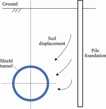
Figure 1 Influence of shield tunneling on bridge piles
2.2 Calculation of vertical displacement of single pile during shield tunneling
Based on the Winkler model, assuming elastic contact between the pile and the soil, and no slippage occurring between the pile and the soil, continuous springs are used to simulate the interaction between the pile and the soil beside the pile [32]. Compared with the Pasternak and Kerr foundations, the Winkler foundation uses independent springs to present the interaction between the piles and the surrounding soil. When the pile nodes are set reasonably, Winkler foundation can greatly simplify the calculation on the premise of ensuring the calculation accuracy, which is the most suitable foundation model for practical engineering in the current theoretical calculation. The calculation diagram is shown in Figure 2, where P0 is the upper load on the node at the pile top. Since the settlement of the pile body and the settlement of the pile side soil are equal at the depth z, the settlement control formula for the influence of the vertical displacement of the soil on the pile body can be obtained as follows:
 (1)
(1)
where δ is the vertical Winkler foundation parameter; Wt(z) is the pile foundation settlement caused by shield tunneling; z is the depth distance; St(z) is the vertical displacement of soil.
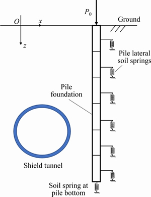
Figure 2 Vertical displacement calculation of single pile
Under normal circumstances, bridge piles will go deep into multi-layer soil. For a single pile in the heterogeneous foundation, pile length L can be divided into n equal parts and expressed in the form of finite difference:
 (2)
(2)
where h is the distance between two adjacent nodes, h=L/n. Assume the pile top as node 0, where the boundary condition P(0)=P0, and the difference equation of the effect of shield tunneling on the vertical direction of a single pile can be obtained as:
 (3)
(3)
where [Kpz] is the vertical stiffness matrix of the pile foundation; {Fz} is the column vector of the vertical external load of the pile foundation; {Wt} is the column vector of the vertical displacement of the pile node during shield tunneling, {Wt}=[Wt,0, Wt,1, …, Wt,i, …, Wt,n-1, Wt,n]T; {St} is the vertical free displacement column vector of soil at the corresponding position of the pile body during shield tunneling, Equation (4) proposed by LOGANATHAN et al [33] is used for calculation, where {St}=[St,0, St,1, …, St,i, …, St,n-1, St,n]T; [Ksz] is the vertical stiffness matrix of soil. The specific expression is shown in Eq. (5):


 (4)
(4)
where R is the radius of the tunnel; ν is the Poisson ratio of soil; x is the horizontal distance between pile and central line of tunnel; g is the equivalent stratum loss parameter; H is the buried depth of tunnel axis.
 (5)
(5)
where  (0≤i≤n).
The vertical displacement of adjacent single pile induced by shield tunneling in the heterogeneous foundation is shown in Eq. (6):
 (6)
(6)
2.3 Calculation of horizontal displacement of single pile during shield tunneling
The following assumptions are used to analyze the free horizontal displacement of the soil at the pile body induced by shield tunneling:
1) Soil is regarded as continuous homogeneous elastomer;
2) The impact of axial forces is not considered;
3) Based on Winkler model, piles are regarded as elastic foundation beams;
4) The interaction between pile and soil is simulated by the continuously distributed springs, and there is no separation between the pile and the soil, satisfying the condition of displacement coordination.
The analysis and calculation diagram of the influence of shield tunneling on the horizontal displacement of adjacent single pile is shown in Figure 3. In Figure 3, H0 is the horizontal force exerted on the node at the pile top, M0 is the bending moment exerted on the node at the top of the pile, and the bottom of the pile is connected by link rods.
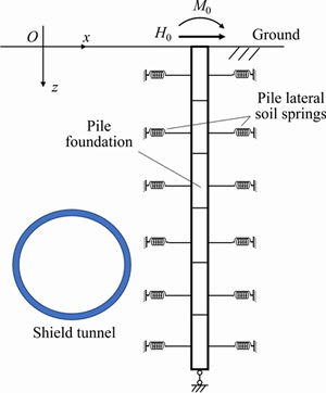
Figure 3 Horizontal displacement calculation of single pile
According to the calculation formula of elastic foundation beam, the settlement control equation of the influence of the horizontal soil displacement on pile body is:
 (7)
(7)
where λ is a horizontal Winkler foundation parameter; ym(z) is the horizontal displacement of pile foundation induced by shield tunneling; Sx(z) is the horizontal displacement of soil.
The single pile in the heterogeneous foundation is divided into n equal parts according to the length of the pile. The finite-difference expressions from points 1 to n-1 are:

 (8)
(8)
The difference equation of the influence of shield tunneling on the horizontal displacement of pile foundation is:
 (9)
(9)
where [Kμx] is the horizontal stiffness matrix of the pile foundation; {Fx} is the horizontal external load column vectors of the pile foundation; {ym} is the horizontal displacement column vector of the pile node during shield tunneling, {ym}=[ym,0, ym,1, …, ym,j, …, ym,n-1, ym,n]T; {Sx} is the horizontal free displacement column vector of soil at the corresponding position of pile body during shield tunneling.
Equation (10) proposed by LOGANATHAN et al [33] is used for calculation, {Sx}=[Sx,0, Sx,1, …, Sx,j, …, Sx,n-1, Sx,n]T; [Kδx] is the horizontal stiffness matrix of soil. The specific expression is shown in Eq. (11).


 (10)
(10)
 (11)
(11)
where  (0≤j≤n).
The horizontal displacement of adjacent single pile induced by shield tunneling in heterogeneous foundation is:
 (12)
(12)
3 Example of shield tunnel passing through bridge piles
3.1 Project overview
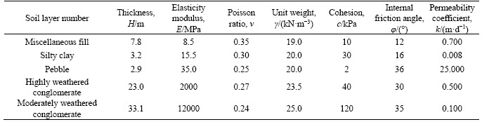
Changsha Metro Line 5 (the first phase of the project between East Laodong Road Station and Huaya Station) runs along the east side of Wanjiali Road in parallel with Wanjiali Rapid Transformation Overpass. The piles of the main bridge of the Wanjiali Overpass are located on the west side of the left line of the section, and the distance between the outer edge of left tunnel and the nearest pile Pm334 of the overpass is only about 3.07 m. The length of the overpass piles is 50 m. Pile Pm331 is 5.20 m away from the outer edge of the left tunnel. Pile Pm332 is 6.38 m away from the outer edge of the left tunnel. Pile Pm333 is 5.79 m away from the outer edge of the left tunnel. The inner diameter and the thickness of the segment lining is 5400 and 300 mm, respectively. The ring width of the segment lining is 1500 mm. The left line tunnel which is closer to the pile foundations is firstly excavated from north to south by the earth-pressure balanced shield tunneling machine. The physical mechanical parameters of the surrounding layers are shown in Table 1.
3.2 Hydrogeological conditions
During the dry season, groundwater flows from both sides to Liuyang river and Guitang River, which discharges to the river in the form of lateral seepage. During the flood season, the water level of the river rises sharply and the river water supplies groundwater to both sides. The groundwater level and water volume change seasonally, leading to large dynamic changes in groundwater. During the preliminary geological survey, the hydrogeological conditions near Guitang River were observed for a long time by means of groundwater stage gauge and leveling. At the same time, combined with the statistical results of water level changes over the years, the groundwater level of the place is determined.
The construction process of this interval tunnel goes through the dry season and the wet season. So based on the fluid-soil interaction theory, a full finite element model and a part finite element model are established, respectively. The full finite element model is used to explore the influence of changes in underground water level during the construction period on shield tunneling, and the part finite element model is used to analyze the influence of water level changes induced by shield tunneling on pile foundation of overpass. The following will combine the numerical calculation results of the above two models to conduct a comprehensive analysis of the influence of shield tunneling on the bridge pile foundation under the fluid-soil interaction.
Table 1 Physical mechanical parameters of surrounded layers
3.3 Field measurement profiles
Precision level, indium steel gauge, theodolite, inclinometer and other equipments are used to measure the settlement of bridge piers and the ground surface settlement trough in front and rear of the piers of Wanjiali Overpass. Two measuring points are arranged symmetrically on each pier. The general situation of field measurement is shown in Figure 4.
4 Establishment of finite element model
4.1 Full finite element model
It usually takes several months for shield tunneling to construct an interval tunnel. During this period, the groundwater level will change significantly with the fluctuation of the river, which will change the effective stress of soil and affect the accuracy of the calculation results. Therefore, the full finite element modeling is carried out for a large area of the site to analyze the influence on pile foundation settlement under three conditions: no considering groundwater, considering stable groundwater and considering continuous change of groundwater under the fluid-soil interaction.
The full finite element model is shown in Figure 5. In order to consider the influence of shield tunneling on soil unloading, the model adopts the modified Mohr-Coulomb criterion.
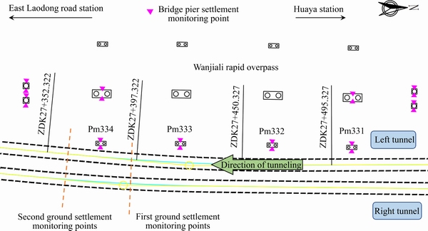
Figure 4 Field measurement layout
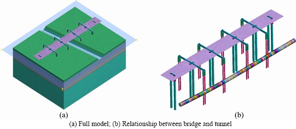
Figure 5 Full finite element model:
4.2 Part finite element model
In order to specifically analyze the influence of shield tunneling on pile foundations of adjacent bridge pile foundations under the fluid-soil interaction, a part finite element model is established at the nearest distance between tunnel and pile foundation in this interval, where the pier number is Pm334. The shortest straight-line distance between the outer edge of left tunnel and the two Φ1200 mm bored concrete piles is only 3.07 m. The part finite element model is shown in Figure 6.
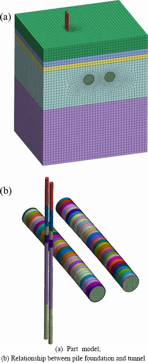
Figure 6 Part finite element model:
4.3 Numerical simulation procedure
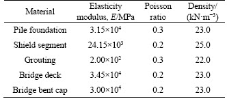
In the simulation construction stage of shield tunneling, step-by-step excavation is adopted. Each forwards 1.5 m. The excavation is realized by “element death” in finite element calculation. Firstly, the thrust force of shield is set at 8000 kN. Secondly, after the excavation of the current ring is completed, the shield segments of the preceding ring are applied. Thirdly, the segment backwall grouting is timely applied, and grouting pressure behind the segment is set at 0.6 MPa. Repeat the above simulated tunnel excavation process until the left line tunnel is fully connected. C35 bored concrete pile is used for the bridge pile, and C50 concrete is used for bridge deck, bridge bent cap and shield segments. In this project, shield segments are assembled in staggered joints to increase segment integrity. In order to simplify calculation, the segments are treated as homogeneous rings and the elasticity modulus of segments is reduced. The reduction coefficient is set as 0.7. Material parameters in the full finite element model and the part finite element model are shown in Table 2.
Table 2 Material parameters in finite element model
4.4 Fluid-soil interaction theory
The fluid-soil interaction theory adopts the three-dimensional Biot theory, as shown in Eq. (13).
 (13)
(13)
The three equations in the formula contain four unknowns: us, vs, ws and u. In order to solve it, an equation needs to be added. According to Darcy’s law, Eq. (14) can be obtained:
 (14)
(14)
where


 εν is volumetric strain; pw is excess pore water pressure; k is the permeability coefficient of soil;
  is the Laplace operator; E′ is the elastic modulus of the soil under effective stress; G′ is the shear modulus of the soil under effective stress; ν′ is Poisson ratio of soil under effective stress; u is pore water pressure; γ′ is the volumetric weight of the soil; γw is the volumetric weight of water; us, vs and ws are displacement components in x, y and z directions, respectively.
The seepage stress coupling analysis module is selected in the finite element software. The groundwater level function is defined according to the field measured groundwater level changing results. In this way, fluid-solid interaction is realized in the process of shield tunneling.
5 Analysis of numerical calculation results
5.1 Analysis of seepage velocity of groundwater caused by river water level variation
Based on the theory of fluid-soil interaction, the groundwater seepage velocity contours caused by river water level variation are shown in Figure 7.
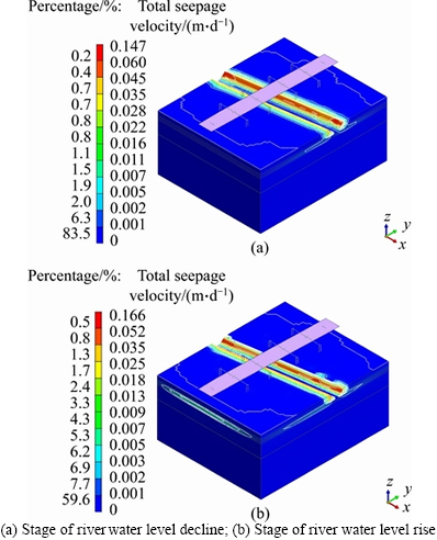
Figure 7 Contours of seepage velocity:
It can be seen from Figure 7 that the groundwater seepage velocity caused by the stage of river water level decline is close to that caused by the stage of river water level rise. Both of them can cause a wide range of changes in water level.
5.2 Analysis of settlement of whole piers
In the full finite element analysis stage, three different calculation methods are selected, which do not consider the influence of groundwater, consider the stable groundwater level, and consider the fluid-soil interaction. Among them, the fluid-soil interaction is realized by defining the water level variation function. Combined with the field measured data, the settlements of bridge piers induced by shield tunneling are analyzed. The settlement comparison of Pm331-Pm334 of bridge piers with shield tunneling is shown in Figure 8. In Figure 8, the starting date of shield construction schedule is marked 50 m before the shield reaches the first pile foundation.
According to the comparison between the finite element calculation results and field measurements, the following three points can be summarized:
1) Before the shield arrives at the position of the bridge piles, the settlement of the bridge piers presents a trend of first increasing and then decreasing. As shown in Figure 9, the main reason is that the shield tunnel will cause stratum loss in front of shield excavation face during the tunneling process, which will increase the settlement of bridge piers. When the shield tunneling machine is located near the bridge piles, the settlement of bridge piers decreases obviously due to the protective effect of the shield tunneling machine’s shell. This trend is in good agreement with the changes measured on site.
2) After the shield passes through the bridge piers, the pier settlement will further increase. When the influence of groundwater is not taken into consideration, the settlement is obviously small, which does not completely conform to the actual situation. The calculated pier settlement results of fluid-soil interaction are more consistent with the measured data. Since the actual construction usually takes several months, it is greatly affected by the precipitation of the river. It is concluded that considering the fluid-soil interaction can better conform to the actual situation.
3) Shield tunneling is a dynamic process of constant parameter optimization. At the same time, the adjacent urban overpass is in normal use stage. It can be concluded from Figure 8 that, compared with the field measured data, the finite element calculation results are more ideal and smoother, and it can better reflect the changing trend of the pier settlement induced by the shield tunneling.
5.3 Analysis of seepage velocity of groundwater caused by shield tunneling
Select the closest distance between the shield tunnel and the bridge pile to establish a part finite element model. Based on the theory of fluid-soil interaction, the groundwater seepage velocity contours induced by shield tunneling are shown in Figure 10.
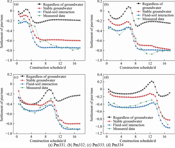
Figure 8 Settlement of piers:
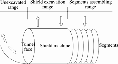
Figure 9 Schematic diagram of shield excavation process
It can be seen from the analysis results in Figure 10 that the seepage velocity decreases successively from the direction of tunnel excavation toward the surface, and the seepage velocity above the shield tunneling is faster. With the continuous advancement of the shield machine, the groundwater directly above the shield gradually loses, and the seepage velocity slows down. The groundwater on both sides supplies seepage to the center of the tunnel, presenting a “U-shaped” flow trend on the ground surface.
5.4 Analysis of ground surface displacement near pile foundation
Based on the part finite element model, the theory of fluid-soil interaction is used to carry out a numerical analysis of shield tunneling to the nearest pile foundation.
The settlement of the bridge pier is closely related to the settlement trough induced by shield tunneling. In order to specifically analyze the differences in settlement troughs caused by the left line excavation under different calculation conditions, the comparisons of the three calculation conditions at two ground settlement measurement points 15 m before and after the Pm334 pier that the groundwater is not considered, the stable groundwater level and the fluid-soil interaction are considered, as shown in Figure 11.
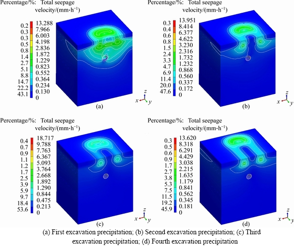
Figure 10 Contours of seepage velocity:
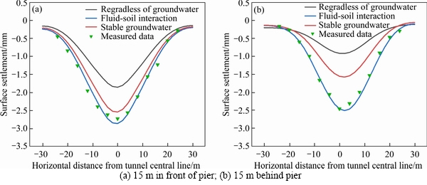
Figure 11 Ground surface settlement trough comparison:
Without considering the effect of groundwater, the width of the ground surface settlement trough at 15 m in the front of the bridge pile is small, and the maximum ground surface settlement caused by the stratum loss at the center line of the tunnel is -1.849 mm. When considering the effect of stable groundwater, the width of the settlement trough is larger, and the maximum ground surface settlement caused by it at the center line of the tunnel is -2.537 mm. When the fluid-soil interaction is combined with the groundwater loss induced by shield tunneling, the width of the settlement trough is the largest, and the maximum ground surface settlement caused by the centerline of the tunnel is -2.857 mm.
The surface settlement at 15 m behind the pile foundation also has similar results. Without considering the effect of groundwater, the maximum ground surface settlement at the center line of the tunnel is -0.924 mm. When considering the effect of stabilizing groundwater, the maximum ground surface settlement at the center line of the tunnel is -1.580 mm. When the fluid-soil interaction is combined with the groundwater loss induced by shield tunneling, the maximum ground surface settlement at centerline of the tunnel is -2.517 mm. The reasons causing difference among the results of the three calculation conditions are as follows: The soil can be considered completely dry soil without considering the groundwater. Since the groundwater level is above the buried depth of the tunnel, the soil weight will change from dry weight to saturated weight when considering the stable groundwater. And the gravity of the upper soil will be increased. Therefore, the calculation results when considering the stable groundwater level is larger than when not considering the groundwater. Based on the fluid-soil interaction, the loss of groundwater is considered on the basis of the stable groundwater, and the settlement of the upper soil will be increased under the further action of the seepage force of groundwater. It has a certain similarity and good agreement with the results of the full model analysis of the settlement of the bridge piers. Comparing with the field measured data, it can be concluded that the fluid-soil interaction conditions considering the change of groundwater level are more consistent with the actual results.
5.5 Vertical displacement of adjacent pile foundation
The displacement laws of the adjacent pile foundation focus on the vertical displacement and horizontal displacement of the pile foundation. The difference of the pile foundation displacement induced by shield tunneling under the same parameters is analyzed respectively under three calculation conditions, not considering groundwater, considering the stable groundwater and considering the fluid-soil interaction. Combined with fluid-soil interaction model, the displacement laws of adjacent pile foundation induced by shield tunneling are summarized. The comparison diagram of pile vertical displacement under three calculation conditions of 3 m before and after shield tunneling to pile foundation are shown in Figure 12. The pile top corresponds to the pile length of 0 m and the pile bottom corresponds to the pile bottom of 50 m.
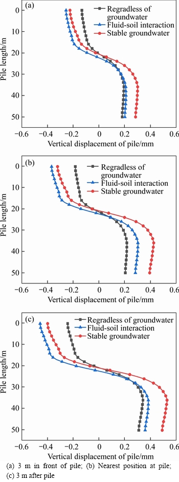
Figure 12 Comparisons of pile vertical displacement:
According to the results in Figure 12, the following conclusions can be drawn:
During the process of shield tunneling passing through the adjacent pile foundation, the pile body located above the top of the tunnel shows a certain settlement, increasing with the decrease of the buried depth of the pile.
Using the fluid-soil interaction theory, when the tunnel is excavated to the position 3 m in front of the pile foundation, the vertical displacement of pile top is -0.255 mm. Within the range from the top of the tunnel to the bottom of the pile, the displacement of the pile body appears to be vertical upward, and the vertical displacement of the pile bottom is 0.203 mm. When the tunnel is excavated to the nearest place from the pile foundation, the vertical displacement of pile top is -0.368 mm, and the vertical displacement of the pile bottom is 0.284 mm. When the tunnel is excavated to the position 3 m after the pile foundation, the vertical displacement of pile top is -0.457 mm, and the vertical displacement of the pile bottom is 0.358 mm. The vertical displacement of pile continues to increase in the process of shield tunneling passes through pile.
The main reasons are that shield tunneling causes stratum loss above the tunnel. At the same time, part of the pile body is settled down under the influence of negative friction; Shield tunneling makes the soil in the area below the tunnel unloaded, and the bottom appears a little rebound. Under the influence of groundwater, the soil around the pile is further deformed, and the lower part of the pile is driven by the soil to produce a small amount of vertical upward displacement.
5.6 Horizontal displacement of adjacent pile foundation
The comparison diagram of pile horizontal displacement under three calculation conditions of 3 m before and after shield tunneling to pile foundation and the pile foundation are shown in Figure 13. When shield tunneling passes through the adjacent pile foundation, the horizontal displacement of pile body appears as an “S” shape, that is, within the vicinity of shield tunnel, the horizontal displacement of pile body deforms away from the shield tunnel, and the horizontal displacement of the pile top and bottom part deforms close to the tunnel.
Similar to the vertical displacement, the horizontal displacement of pile continues to increase in the process of shield tunneling passing through pile. The maximum value appears near the tunnel. When the tunnel is excavated to the position 3 m in front of the pile foundation, the maximum horizontal displacement of pile is -0.515 mm. When the tunnel is excavated to the nearest place from the pile foundation, the maximum horizontal displacement of pile is -0.675 mm. When the tunnel is excavated to the position 3 m after the pile foundation, the horizonal displacement of pile is -0.854 mm.
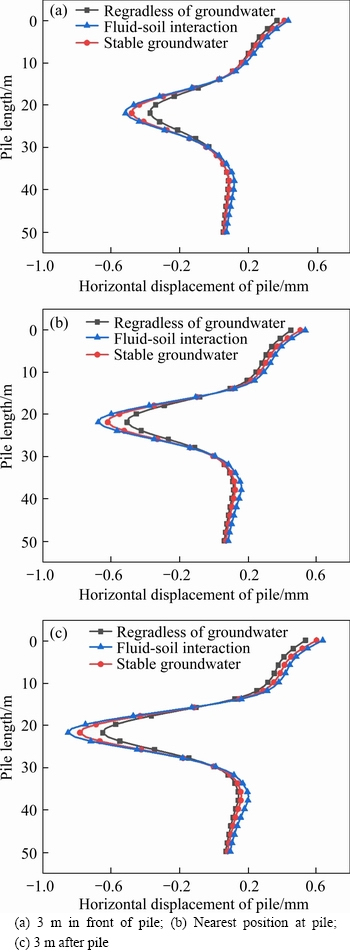
Figure 13 Comparisons of pile horizontal displacement:
The main reasons are the loss of upper strata induced by shield tunneling and the rebound of soil below the bottom of the tunnel, as shown in Figure 1. Therefore, when the shield passes through the bridge piles at a close distance, attention should be paid to the bending moment of the pile at the closest position to the tunnel to ensure that the pile will not be greatly affected.
By comparing the vertical and horizontal displacement of the pile under the three calculation conditions, it can be found that the vertical and horizontal displacement of the pile is the smallest when the groundwater effect is not considered, and the calculation results considering the stable groundwater are slightly less than the calculation results considering fluid-soil interaction. This is in good agreement with the measured data.
To sum up, without considering the effect of groundwater, the calculation results will be small, and the calculation method of fluid-soil interaction is more practical and has better engineering guiding significance.
5.7 Analysis of stress characteristics of adjacent pile foundation
The change process of pile stress induced by shield tunneling is shown in Figure 14. Before the pile foundation enters the influence range of shield, the overall performance of pile stress is a linear distribution from top to bottom. As the shield continues to approach, the pile body presents a greater stress concentration near the closest position to the tunnel. As the shield continues to excavate, the stress will continue to increase. If the stress is too high, it is necessary to reinforce by the sleeve valve barrel grouting or set partition before construction to reduce the local stress of the pile body. The stress difference between the 4th ring after excavation and the 10th ring after excavation is small. Therefore, it can be considered that the stress generated by the pile foundation after the shield passes through the 4-ring range has been basically stable.
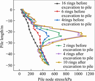
Figure 14 Process of pile nodal stress variation caused by shield tunneling
In practical engineering, both high pressure rotary jet grouting and sleeve valve barrel grouting can be used to set grouting isolation between piles and tunnels. On the one hand, the grouting isolation can reduce the displacement of the surrounding soil near the pile foundation. On the other hand, the grouting isolation can further block the groundwater seepage caused by shield tunneling in water-rich areas due to its waterproof properties.
6 Conclusions
1) According to the comparison between the finite element calculation results and the field measured data, it is found that when the groundwater level in the site is easily affected by seasonal changes or has an obvious hydraulic relationship with adjacent rivers, the calculated pier settlement results using the theory of fluid-soil interaction are closer to reality than those without considering groundwater and considering stable groundwater.
2) During the shield tunneling process, the seepage velocity in front of the shield machine decreases successively from the tunnel excavation surface, and the seepage velocity of the soil above the shield before excavation is faster than that of the surrounding soil. After the shield passes, the groundwater on both sides presents a “U”-shaped flow trend of seepage on the ground surface supplying to the upper part of the tunnel. Pile foundation will be further deformed under the action of seepage force.
3) When the position and construction parameters are the same, the ground surface settlement is the smallest without considering groundwater, and the vertical and horizontal displacement of the pile is also smaller than that of the other two conditions. Therefore, when the influence of groundwater level cannot be ignored, the results of the displacement of pile foundation will be small by using the calculation method without considering the influence of groundwater. The calculated displacement of pile foundation using stable groundwater level can be improved, but it cannot reflect the actual situation of groundwater level change.
4) When the shield passes through the bridge pile foundation, the vertical displacement of pile body appears as the settlement of pile body in the range above the top of the tunnel and the vertical upward displacement of pile body in the range below the top of the tunnel. The horizontal displacement of the pile body appears as displacement in the direction away from the tunnel near the excavation area of the tunnel, and is distributed in an “S” shape. As the shield approaches the pile foundation, the pile body stress gradually changes from the original trapezoidal distribution to a stress concentration near the tunnel excavation area. With the shield continues to excavate, the pile body stress stabilizes.
Contributors
The overarching research goals were developed by HUANG Kan, SUN Yi-wei, ZHOU De-quan and LI Yu-jian. HUANG Kan provided the concept and edited the draft of manuscript. SUN Yi-wei established the finite models and calculated the results. SUN Yi-wei, JIANG Meng and HUANG Xian-qiang analyzed the data. The initial draft of the manuscript was written by SUN Yi-wei. All authors replied to reviewers’ comments and revised the final version.
Conflict of interest
HUANG Kan, SUN Yi-wei, ZHOU De-quan, LI Yu-jian, JIANG Meng and HUANG Xian-qiang declare that they have no conflict of interest.
References
[1] DING Z, WEI X J, WEI G. Prediction methods on tunnel-excavation induced surface settlement around adjacent building [J]. Geomechanics and Engineering, 2017, 12(2): 185-195. DOI: 10.12989/gae.2017.12.2.185.
[2] LIU C H, BEZUIJEN A, YANG M, CACHIM P. Elastic analysis of ground movements around a tunnel considering a buoyant lining moving upwards [J]. International Journal for Numerical and Analytical Methods in Geomechanics, 2019, 43: 1562-1575. DOI: 10.1002/nag.2902.
[3] SU Y, SU Y H, ZHAO M H, VLACHOPOULOS N. Tunnel stability analysis in weak rocks using the convergence confinement method [J]. Rock Mechanics and Rock Engineering, 2021, 54: 559-582. DOI: 10.1007/s00603-020-02304-y.
[4] MU L L, HUANG M S, FINNO R J. Tunneling effects on lateral behavior of pile rafts in layered soil [J]. Tunneling and Underground Space Technology, 2012, 28: 192-201. DOI: 10.1016/j.tust.2011.10.010.
[5] ZHANG Z G, XU C, GONG J F. Influence of tunneling on deflection of adjacent piles considering shearing displacement of foundation and 3D effects of lateral soils beside piles [J]. Chinese Journal of Geotechnical Engineering, 2016, 38(5): 846-856. DOI: 10.11779/CJGE201605010. (in Chinese)
[6] ZHANG Z G, HUANG M S, XU C, JIANG Y J, WANG W D. Simplified solution for tunnel-soil-pile interaction in Pasternak’s foundation model [J]. Tunneling and Underground Space Technology, 2018, 78: 146-158. DOI: 10.1016/j.tust.2018.04.025.
[7] NG C W W, LU H, PENG S Y. Three-dimensional centrifuge modelling of the effects of twin tunnelling on an existing pile [J]. Tunnelling and Underground Space Technology, 2013, 35: 189-199. DOI: 10.1016/j.tust.2012.07.008.
[8] FRANZA A, MARSHALL A M. Centrifuge and real-time hybrid testing of tunneling beneath piles and piled buildings [J]. Journal of Geotechnical and Geoenvironmental Engineering, 2019, 145(3): 04018110. DOI: 10.1061/(ASCE) GT.1943-5606.0002003.
[9] SONG G Y, MARSHALL A M. Centrifuge study on the influence of tunnel excavation on piles in sand [J]. Journal of Geotechnical and Geoenvironmental Engineering, 2020, 146(12): 04020129. DOI: 10.1061/(ASCE)GT.1943-5606. 0002401.
[10] SOOMRO M A, MANGI N, XIONG H, KUMAR M, MANGNEJO D A. Centrifuge and numerical modelling of stress transfer mechanisms and settlement of pile group due to twin stacked tunneling with different construction sequences [J]. Computers and Geotechnics, 2020, 121: 103449. DOI: 10.1016/j.compgeo.2020.103449.
[11] SOOMRO M A, HONG Y, NG C W W, LU H, PENG S Y. Load transfer mechanism in pile group due to single tunnel advancement in stiff clay [J]. Tunneling and Underground Space Technology, 2015, 45: 63-72. DOI: 10.1016/j.tust. 2014.08.001.
[12] SOOMRO M A, NG C W W, LIU K, MEMON N A. Pile responses to side-by-side twin tunneling in stiff clay: Effects of different tunnel depths relative to pile [J]. Computers and Geotechnics, 2017, 84: 101-116. DOI: 10.1016/j.compgeo. 2016.11.011.
[13] MESCHKE G, NINIC J, STASCHEIT J, ALSAHLY A. Parallelized computational modeling of pile-soil interactions in mechanized tunneling [J]. Engineering Structures, 2013, 47: 35-44. DOI: 10.1016/j.engstruct.2012.07.001.
[14] KHABBAZ H, GIBSON R, FATAHI B. Effect of constructing twin tunnels under a building supported by pile foundations in the Sydney central business district [J]. Underground Space, 2019, 4(4): 261-276. DOI: 10.1016/j.undsp.2019.03.008.
[15] YANG M, SUN Q, LI W C, MA K. Three-dimensional finite element analysis on effects of tunnel construction on nearby pile foundation [J]. Journal of Central South University of Technology, 2011, 18(3): 909-916. DOI: 10.1007/s11771-011-0780-9.
[16] ZHAO M H, LIU D P, ZHANG L, JIANG C. 3D finite element analysis on pile-soil interaction of passive pile group [J]. Journal of Central South University of Technology, 2008, 15(1): 75-80. DOI: 10.1007/s11771-008-0016-9.
[17] JONGPRADIST P, KAEWSRI T, SAWATPARNICH A, SUWANSAWAT S, YOUWAI S, KONGKITKUL W, SUNITSAKUL J. Development of tunneling influence zones for adjacent pile foundations by numerical analyses [J]. Tunneling and Underground Space Technology, 2013, 34: 96-109. DOI: 10.1016/j.tust.2012.11.005.
[18] ZHAO B Y, WANG X P, ZHANG C, LI W C, ABBASSI R, CHEN K. Structural integrity assessment of shield tunnel crossing of a Railway Bridge using orthogonal experimental design [J]. Engineering Failure Analysis, 2020, 114: 104594. DOI: 10.1016/j.engfailanal.2020.104594.
[19] WANG Z, ZHANG K W, WEI G, LI B, LI Q, YAO W J. Field measurement analysis of the influence of double shield tunnel construction on reinforced bridge [J]. Tunneling and Underground Space Technology, 2018, 81: 252-264. DOI: 10.1016/j.tust.2018.06.018.
[20] SIRIVACHIRAPORN A, PHIENWEJ N. Ground movements in EPB shield tunneling of Bangkok subway project and impacts on adjacent buildings [J]. Tunneling and Underground Space Technology, 2012, 30: 10-24. DOI: 10.1016/j.tust. 2012.01.003.
[21] ZHANG X M, YANG J S, ZHANG Y X, GAO Y F. Cause investigation of damages in existing building adjacent to foundation pit in construction [J]. Engineering Failure Analysis, 2018, 83: 117-124. DOI: 10.1016/j.engfailanal. 2017.09.016.
[22] ZHOU D Q, FENG C X. Engineering characteristics and reinforcement program of inclined pre-stressed concrete pipe piles [J]. KSCE Journal of Civil Engineering, 2019, 23(9): 3907-3923. DOI: 10.1007/s12205-019-0192-1.
[23] HUANG K, SUN Y W, HE J, HUANG X Q, JIANG M, LI Y J. Comparative study on grouting protection schemes for shield tunneling to adjacent viaduct piles [J]. Advances in Materials Science and Engineering, 2021, 2021: 5546970. DOI: 10.1155/2021/5546970.
[24] HUANG K, SUN Y W, HUANG X Q, LI Y J, JIANG M, LIU K N. Effects of different construction sequences on ground surface settlement and displacement of single long pile due to twin paralleled shield tunneling [J]. Advances in Civil Engineering, 2021, 2021: 5559233. DOI: 10.1155/2021/ 5559233.
[25] LI X F, DU S J, CHEN B. Unified analytical solution for deep circular tunnel with consideration of seepage pressure, grouting and lining [J]. Journal of Central South University, 2017, 24(6): 1483-1493. DOI: 10.1007/s11771-017-3552-3.
[26] WU C Z, HONG Y, CHEN Q S, KAREKAL S. A modified optimization algorithm for back analysis of properties for coupled stress-seepage field problems [J]. Tunneling and Underground Space Technology, 2019, 94: 103040. DOI: 10.1016/j.tust.2019.103040.
[27] YANG X L, HUANG F. Stability analysis of shallow tunnels subjected to seepage with strength reduction theory [J]. Journal of Central South University of Technology, 2009, 16(6): 1001-1005. DOI: 10.1007/s11771-009-0166-4.
[28] ZHANG F S, WANG T, LIU F, PENG M, FURTNEY J, ZHANG L M. Modeling of fluid-particle interaction by coupling the discrete element method with a dynamic fluid mesh: Implications to suffusion in gap-graded soils [J]. Computers and Geotechnics, 2020, 124: 103617. DOI: 10.1016/j.compgeo.2020.103617.
[29] WANG Y C, LI Z Y, JING H W, LI Y B, WANG M T. Study on the seepage characteristics of deep buried tunnels under variable high-pressure water heads [J]. Bulletin of Engineering Geology and the Environment, 2021, 80: 1477-1487. DOI: 10.1007/s10064-020-01986-6.
[30] LI Z, LUO Z J, XU C H, TAN J Z. 3D fluid-solid full coupling numerical simulation of soil displacement induced by shield tunneling [J]. Tunneling and Underground Space Technology, 2019, 90: 174-182. DOI: 10.1016/j.tust.2019.03.020.
[31] HUANG K, YANG W J, MA Q A, AN Y L, LI Y, ZHOU J W, QIU L. Influence of foundation excavation pit on adjacent metro tunnel using fluid-solid mechanics theory [J]. Journal of Central South University (Science and Technology), 2019, 50(1): 198-205. DOI: 10.11817/j.issn.1672-7207.2019.01. 025. (in Chinese)
[32] AN Y L, ZHOU J, OUYANG P B, LI J H. Analysis of tunnel face stability with the advanced pipes support [J]. Journal of Central South University, 2021, 28(2): 604-617. DOI: 10.1007/s11771-021-4625-x.
[33] LOGANATHAN N, POULOS H G. Analytical prediction for tunneling-induced ground movements in clays [J]. Journal of Geotechnical and Geoenvironmental Engineering, 1998, 124(9): 846-856. DOI: 10.1061/(ASCE)1090-0241(1998) 124:9(846).
(Edited by YANG Hua)
中文导读
分层地基中富水隧道盾构施工对既有桥梁桩基的影响
摘要:当前盾构施工常需穿越大量桥桩基础,关于盾构开挖引起地下水渗流对邻近桥桩影响的研究较少。基于Winkler地基模型推导盾构施工对邻近桥桩变形的计算公式,建立整体和局部三维有限元模型。分析不考虑地下水作用、考虑稳定地下水作用及流固耦合三种计算工况下桥墩沉降量、地表沉降槽、桩身竖直、水平变形量及桩身应力变化趋势。研究结果表明:当不考虑地下水作用时,计算数值偏小;在流固耦合下开挖面的前上方土体渗流速度较周围土体的渗流速度快,在盾构通过后,两侧地下水在地表呈现出“U”形向隧道上方补给的流动趋势;桩身竖向变形以隧道顶部水平位置为界,上部桩身沉降,下部桩身向上变形;桩身水平变形呈现出连续“S”形分布,在隧道附近产生应力集中。流固耦合的计算结果与现场实测数据更吻合,符合实际情况。
关键词:盾构隧道;桥梁桩基;Winkler地基;流固耦合;数值分析
Foundation item: Project(52078060) supported by the National Natural Science Foundation of China; Project(2020JJ4606) supported by the National Science Foundation of Hunan Province, China; Project(18A127) supported by the Key Foundation of Education Department of Hunan Province, China; Project(2018IC19) supported by the International Cooperation and Development Project of Double-First-Class Scientific Research in Changsha University of Science & Technology, China
Received date: 2020-12-03; Accepted date: 2021-06-12
Corresponding author: ZHOU De-quan, PhD, Professor; Tel: +86-13975809351; E-mail: zhoudequan28@163.com; HUANG Kan, PhD, Associate Professor; Tel: +86-18711031292; E-mail: hk_616@csust.edu.cn; ORCID: https://orcid.org/0000-0003-0489-6388

